EP0532145B1 - Zerstückelungsvorrichtung - Google Patents
Zerstückelungsvorrichtung Download PDFInfo
- Publication number
- EP0532145B1 EP0532145B1 EP92301537A EP92301537A EP0532145B1 EP 0532145 B1 EP0532145 B1 EP 0532145B1 EP 92301537 A EP92301537 A EP 92301537A EP 92301537 A EP92301537 A EP 92301537A EP 0532145 B1 EP0532145 B1 EP 0532145B1
- Authority
- EP
- European Patent Office
- Prior art keywords
- ribs
- macerator
- side rail
- cutters
- slots
- Prior art date
- Legal status (The legal status is an assumption and is not a legal conclusion. Google has not performed a legal analysis and makes no representation as to the accuracy of the status listed.)
- Expired - Lifetime
Links
Images



Classifications
-
- B—PERFORMING OPERATIONS; TRANSPORTING
- B02—CRUSHING, PULVERISING, OR DISINTEGRATING; PREPARATORY TREATMENT OF GRAIN FOR MILLING
- B02C—CRUSHING, PULVERISING, OR DISINTEGRATING IN GENERAL; MILLING GRAIN
- B02C18/00—Disintegrating by knives or other cutting or tearing members which chop material into fragments
- B02C18/0084—Disintegrating by knives or other cutting or tearing members which chop material into fragments specially adapted for disintegrating garbage, waste or sewage
- B02C18/0092—Disintegrating by knives or other cutting or tearing members which chop material into fragments specially adapted for disintegrating garbage, waste or sewage for waste water or for garbage
-
- B—PERFORMING OPERATIONS; TRANSPORTING
- B02—CRUSHING, PULVERISING, OR DISINTEGRATING; PREPARATORY TREATMENT OF GRAIN FOR MILLING
- B02C—CRUSHING, PULVERISING, OR DISINTEGRATING IN GENERAL; MILLING GRAIN
- B02C18/00—Disintegrating by knives or other cutting or tearing members which chop material into fragments
- B02C18/06—Disintegrating by knives or other cutting or tearing members which chop material into fragments with rotating knives
- B02C18/14—Disintegrating by knives or other cutting or tearing members which chop material into fragments with rotating knives within horizontal containers
- B02C18/142—Disintegrating by knives or other cutting or tearing members which chop material into fragments with rotating knives within horizontal containers with two or more inter-engaging rotatable cutter assemblies
Definitions
- the present invention relates to a macerator.
- One form of macerator as shown, for example, in GB-A-1569672, includes first and second parallel contra rotating shafts, each having a plurality of alternate cutters and spacers of the same axial thickness, the cutters of the first shaft being interleaved with those of the second shaft.
- Each cutter has a plurality of teeth arranged around its periphery and circumferentially spaced locations.
- side rails Mounted adjacent to the cutters, on the side walls of the housing, are side rails which have radially inner surfaces which are arcuate and closely adjacent to the teeth of the cutters as they rotate. While this has proved to be reasonably satisfactory, the flow rate, particularly of a liquid-borne, in particular water-borne, material to be macerated is reduced rather severely because of the general blockage provided by the cutters and the side rails.
- the ribs and slots are angled at between 15°and 45° with respect to the planes of the cutting discs.
- the present invention there is provided a design of the side rails in which the ribs, and the slots therebetween, are angled relative to the planes of the cutter discs, whereby the cutter teeth of the cutter discs each pass in close proximity to a plurality of ribs.
- the shafts While it is practical for the shafts to be mounted in any orientation, they are preferably mounted in a generally vertical plane.
- the angling of the ribs and slots therebetween is such as to extend downwardly in the direction of flow, that is to say in the direction of peripheral movement of the cutters as they pass the side rail.
- the side rail has a top wall and a bottom wall which extends substantially in the same plane as the uppermost and the lowermost of the cutting discs respectively and that rib or those ribs which would normally intersect the top and bottom walls are made shorter, at their upper and lower ends, to define "header channels" thereby ensuring that each of the angled slots has an inlet and an outlet.
- each of the ribs is chamfered or bevelled at its free edge, the bevelling preferably extending downwardly at the free edge.
- one of a pair of slotted side rails is indicated by the general reference numeral 2 and has a rear wall 4.
- a plurality of ribs 6 of the side rail have corresponding slots 8 therebetween, the ribs having arcuate front edges 10.
- the slots 8 and the ribs 6 are parallel to cutting elements 16 and 18 of the macerator shown in Figure 2. While Figure 2 only shows one side rail, there will be a mirror image side rail mounted on the other side with the ribs 6 in facing relation to the cutter discs 18.
- the macerator 12 illustrated in Figure 2 has two drive shafts 14 upon which cutting elements 16 and 18 are mounted. Planar spacers 20 and 22 are mounted between the cutting discs and are of the same thickness as the cutting discs.
- the discs 16, 18 are mounted opposite the ribs 6 and that the spacers 20, 22 are mounted opposite the slots 8. It will be appreciated that the cutting elements 16, 18 are spaced apart by the planar spaces 20, 22 respectively and these are fixedly mounted on the shaft 14.
- the cutting elements 16 and 18 are interleaved and the teeth 24 of the cutting elements are in close proximity to the bases of the other stack and in close proximity to the front edges 10 of the ribs 6.
- the ribs are aligned with the flow direction of liquid through the comminuting chamber and spaced to allow passage of liquid through the slots between the ribs. Liquid borne fine particles of solid material find passage through the slots 8 but the ribs prevent passage of larger pieces of unreduced material.
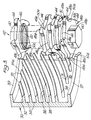
- a side rail according to the present invention is indicated by the general reference numeral 30 in which it is shown on Figure 3, in an exploded perspective view of the rail and a macerator stack 42.
- Angled ribs 32 formed in the side rail define slots 34, the ribs 32 ensuring that liquid borne solid material flowing through a slot crosses a plane of at least two cutting elements 44. Crossing the plane of several cutting elements increases the likelihood that a piece of solid material will contact the cutting elements 44 several times and be adequately reduced to a manageable particle side.
- the angled ribs 32 present arcuately angled side rail surfaces 36 to the periphery of the macerator stack 42 which is mounted on shaft 40.
- the cutters 44 of the macerator stack 42 are each spaced from their neighbour by a spacer 46 defined by the thickness of the spacers 52 as shown in Figure 4.
- the angled ribs 32 are angled so that the surfaces 36 extend at an angle of between 15° and 45° to the planes of the cutting discs.
- the angle may be varied with arc length of the angled side rails 30 to ensure that a maximum number of recesses will cross the plane of more than one cutting element 44.
- a shorter arc length will require a steeper angle to ensure that sufficient crossings of the cutters and the ribs occurs, i.e. so that there are at least two and preferably several cutting planes.
- each rib 32 is at least partly bevelled.
- the bevelled front edges 38 allow for a smaller space between the front edge of the ribs and the periphery of the teeth of the cutting elements without increasing the likelihood that solid material will become lodged between the angled ribs and the cutting elements.
- the shafts 40 are vertical, as shown, the bevelled front edges 38 are preferably bevelled downwardly which serves to channel solid material within the slot of a lower angled rib and into contact with the cutting element 44.
- angled ribs 32 and angled slots 34 are shown in a partial sectional view of the macerator stack in phantom, positioned in an operation mode, with the angled ribs of the side rail being shown in full lines.
- the angled ribs 32 along with the bevelled front edges 38 and the angled recesses 32 are shown differently in Figure 5 with the associated shaft 40 and macerator stack 42 along with cutting elements 44 and cutting teeth 48.
- Figure 5 provides a view of the improved macerator of the invention, and shows the angled slots 34 that ensure liquid borne solid material passing through a slot crosses the plane of at least two cutting elements 44 and its cutting teeth 48. It can be seen that the upper and lower faces 30a and 30b of the side rails are chamfered.
- each cutter of the stack is illustrated as having 5 circumferentially spaced teeth 48a, 48b, 48c, 48d and 48e. It can be seen that each tooth has a tip 49a, 49b, 49c, 49d and 49e respectively and a generally arcuate concave front face 50a, 50b, 50c, 50d and 50e.
- the front face 50a and tip 49a extends substantially parallel to the axis of the cutter, so that it is essentially "square".
- the front faces 50b and 50d are angled to one side of the axis of the cutter and the alternate front faces 50c and 50e are angled to the other side of the axis.
- the rear faces 51 are inclined to provide a ramp like configuration and are each provided with serrations 52, the angle of the serrations being approximately 60°.
- the rear faces 51 are arcuately convex between the serrations 52 and the tips 49.
- the front faces 50b, 50c, 50d and 50e are inclined at approximately 30° to the axis in alternately opposite directions.
- a good scissor action and it will be observed that the cutting action takes place only in the one direction of rotation. This is bound to make the cutter strong and not too prone to damage.
- the one tooth 48a has a "square" cutting face and this improves the catchment of the solids and the drag of the item being macerated into the bank of cutters. Because the other teeth have alternate angles, this tends to equal out any side thrust and reduces the possibility of breakage.
- angled ribs 32 and angled recesses 34 may be formed of cast metal these elements may be metal stamped or formed by other metallurgical processes. Rather than being unitary, the elements may be formed of component metal parts welded together but taking substantially the form shown.
- the macerator with the angled ribs and slots is shown as having a generally rectangular housing which is transversely elongate, the housing could be generally cylindrical and the angle side rails and supporting wall could be semi-cylindrical in form.
- the side rails 30, it will be seen, have concave arcuate front edges 36 the curvature of which conforms substantially to the curvature of the locus of the teeth 48 so that the angled ribs 32 are only spaced a short distance from the path of movement of the teeth 48.
- the provision of the angled ribs and slots ensures a far better maceration and reduces the likelihood of larger, particularly sheet like solid material, bypassing the cutters.
- the apparatus of the present invention is equally mountable in an open topped channel with the axis of the cutter stacks extending vertically and the side rails mounted on either side of the channel.
- the structure of the present invention is designed particularly to deal with raw sewage, sewage cleaning and sludge maceration and can, as indicated, be used in a channel or in a pipeline. It is believed that the structure of the present invention can operate over a wide range of capacities. For example, a capacity of up to 500 cubic meters per hour having a throat size ranging from 300 mm to 1500 mm can be provided wherein various sizing of the apparatus is taken into consideration when determining the dimensions of the side rails according to the invention. Any size of apparatus can be supplied to operate in a vertical or horizontal orientation or in an intermediate position between the vertical and horizontal.
Landscapes
- Engineering & Computer Science (AREA)
- Food Science & Technology (AREA)
- Environmental & Geological Engineering (AREA)
- Crushing And Pulverization Processes (AREA)
- Paper (AREA)
- Seal Device For Vehicle (AREA)
- Portable Nailing Machines And Staplers (AREA)
- Secondary Cells (AREA)
Claims (15)
- Zerstückelungsvorrichtung, enthaltend eine Zerstückelungskammer, Kammerseitenwände, erste und zweite parallele, gegensinnig drehende Wellen (14, 40), die zwischen den Seitenwänden durch die Kammer verlaufen, eine Mehrzahl von an jeder der ersten und zweiten Wellen einander abwechselnd angebrachten Schneidwerkzeugen (16, 18, 44) und Abstandhaltern (20, 22, 46) derselben axialen Dicke, wobei die Schneidwerkzeuge der ersten Welle mit jenen der zweiten Welle verschachtelt sind und wenigstens ein Messer (24, 48) daran enthalten und jedes Messer eine vordere Schneidfläche (50) hat, mit jeder Seitenwand in Zusammenhang stehende Seitenführungen (2, 30), wobei jede Führung eine Mehrzahl von beabstandeten parallelen Rippen (6, 32) enthält und die Rippen zwischen sich Schlitze (8, 34) ausbilden, und Kantenflächen (10, 36) der Rippen in dichter Nähe zu den Messern der Schneidwerkzeuge, indem die Messer daran benachbart vorbeigehen,
dadurch gekennzeichnet,
daß die parallelen Rippen (32) jeder seitlichen Führung in einem spitzen Winkel gegen die Ebenen der Schneidwerkzeuge der benachbarten Welle abgewinkelt sind. - Zerstückelungsvorrichtung nach Anspruch 1,
dadurch gekennzeichnet,
daß der spitze Winkel zwischen 15° und 45° ist. - Zerstückelungsvorrichtung nach Anspruch 1 oder 2,
dadurch gekennzeichnet,
daß die bezüglich der Drehachse der benachbarten Welle (40) radial innenliegenden Kantenflächen (36) der Rippen (32) konkav sind, wobei die konkaven Kantenflächen der Rippen dem Bewegungsweg der Enden der Schneidwerkzeugmesser entsprechen. - Zerstückelungsvorrichtung nach Anspruch 3 in Verbindung mit Anspruch 2,
dadurch gekennzeichnet,
daß die Länge der konkaven Fläche gemessen um den Umfang des Schneidwerkzeugs umgekehrt proportional zum Neigungswinkel ist. - Zerstückelungsvorrichtung nach einem der vorhergehenden Ansprüche,
dadurch gekennzeichnet,
daß die ersten und zweiten Wellen (40) vertikal montiert sind, und daß die Rippen (32) der Seitenführungen in der Bewegungsrichtung der dazu benachbarten Schneidwerkzeugmesser abwärts geneigt sind. - Zerstückelungsvorrichtung nach Anspruch 5,
dadurch gekennzeichnet,
daß jede seitliche Führung eine Deckwand (39) und eine Bodenwand (37) enthält, daß sich wenigstens einige der Schlitze (34) in eine Seitenfläche der Seitenführung öffnen, um einen Materialdurchgang davon in die Schlitze zuzulassen, und daß die Deckwand (39) und die Bodenwand (37) jeder Seitenführung von den oberen und unteren Kanten jener unter einem Winkel verlaufenden Rippen beabstandet sind, die nicht zur Seite der Seitenführung verlaufen, um dadurch einen Sammeldurchgang (35, 35a) für in den damit verbundenen Schlitzen strömendes Material bereitzustellen. - Zerstückelungsvorrichtung nach einem der vorhergehenden Ansprüche,
dadurch gekennzeichnet,
daß die freien Kanten der Rippen abgeschrägt sind (bei 38). - Zerstückelungsvorrichtung nach Anspruch 7,
dadurch gekennzeichnet,
daß die ersten und zweiten Wellen (40) vertikal montiert und die Abschrägungen (38) an den oberen Kanten der Rippen ausgebildet sind. - Zerstückelungsvorrichtung nach einem der vorhergehenden Ansprüche,
dadurch gekennzeichnet,
daß jedes Schneidwerkzeug (44) mehrere umfangsmäßig beabstandete Messer (50) enthält, jedes Messer eine allgemein rampenförmige, geneigte Rückseite (51) hat, und die Vorderseite (50a) wenigstens eines Messers im wesentlichen parallel zur Achse des Schneidwerkzeugs verläuft und die Vorderseiten einer Mehrzahl der anderen Messer (50b - 50d) gegen die Achse des Schneidwerkzeugs geneigt sind. - Zerstückelungsvorrichtung nach einem der vorhergehenden Ansprüche,
dadurch gekennzeichnet,
daß die Zerstückelungskammer die Seitenwände eines Kanals enthält. - Zerstückelungsvorrichtung nach einem der Ansprüche 1 bis 9,
dadurch gekennzeichnet,
daß die Zerstückelungskammer den Innenraum eines Gehäuses enthält, das an entgegengesetzten Seiten der zwischen den rotierenden Schneidwerkzeugen gebildeten Berührungslinie eine Einlaß- und eine Auslaßöffnung hat. - Seitenführung (2, 30) zur Verwendung in einer Zerstückelungsvorrichtung mit ersten und zweiten parallelen Wellen (14, 40), wobei jede Welle eine Mehrzahl von einander abwechselnden Schneidwerkzeugen (16, 18, 44) und Abstandhaltern (20, 22, 46) derselben axialen Dicke hat und die Schneidwerkzeuge der ersten Welle mit jenen der zweiten Welle verschachtelt sind, die Seitenführung (2, 30) einen Seitenführungskörper (4, 30) mit oberen und unteren parallelen Flächen enthält und von dem Körper eine Mehrzahl von im wesentlichen parallelen Rippen (6, 32) absteht, um dazwischen eine Mehrzahl von Schlitzen (8, 34) zu bestimmen,
dadurch gekennzeichnet,
daß die Rippen eine bogenförmige freie Kante haben, die gegenüber den rotierenden Schneidwerkzeugen der Zerstückelungsvorrichtung positionierbar sind, wobei die Rippen in einem spitzen Winkel gegen die oberen und unteren Flächen geneigt sind, um dazwischen unter einem Winkel verlaufende Schlitze zu bestimmen. - Seitenführung nach Anspruch 12,
dadurch gekennzeichnet,
daß der spitze Winkel zwischen 15° und 45° ist. - Seitenführung nach Anspruch 12 oder 13,
dadurch gekennzeichnet,
daß die bezüglich der Drehachse der benachbarten Welle (40) radial innenliegenden Kantenflächen (36) der Rippen (32) konkav sind, wobei die konkaven Kantenflächen der Rippen dem Bewegungsweg der Enden der Schneidwerkzeugmesser entsprechen. - Seitenführung nach Anspruch 14 in Verbindung mit Anspruch 13,
dadurch gekennzeichnet,
daß die Länge der konkaven Fläche gemessen um den Umfang des Schneidwerkzeugs umgekehrt proportional zum Neigungswinkel ist.
Applications Claiming Priority (2)
| Application Number | Priority Date | Filing Date | Title |
|---|---|---|---|
| GB9119258 | 1991-09-09 | ||
| GB9119258A GB2259260A (en) | 1991-09-09 | 1991-09-09 | Macerator. |
Publications (2)
| Publication Number | Publication Date |
|---|---|
| EP0532145A1 EP0532145A1 (de) | 1993-03-17 |
| EP0532145B1 true EP0532145B1 (de) | 1995-07-26 |
Family
ID=10701142
Family Applications (1)
| Application Number | Title | Priority Date | Filing Date |
|---|---|---|---|
| EP92301537A Expired - Lifetime EP0532145B1 (de) | 1991-09-09 | 1992-02-24 | Zerstückelungsvorrichtung |
Country Status (6)
| Country | Link |
|---|---|
| EP (1) | EP0532145B1 (de) |
| AT (1) | ATE125469T1 (de) |
| AU (1) | AU649877B2 (de) |
| DE (1) | DE69203681T2 (de) |
| ES (1) | ES2074820T3 (de) |
| GB (1) | GB2259260A (de) |
Families Citing this family (2)
| Publication number | Priority date | Publication date | Assignee | Title |
|---|---|---|---|---|
| GB9423623D0 (en) * | 1994-11-23 | 1995-01-11 | Mono Pumps Ltd | Macerator |
| GB2297927A (en) * | 1995-02-17 | 1996-08-21 | Mono Pumps Ltd | Macerator |
Family Cites Families (6)
| Publication number | Priority date | Publication date | Assignee | Title |
|---|---|---|---|---|
| US1434360A (en) * | 1919-04-18 | 1922-11-07 | William F Bach | Self-scouring crushing machine |
| DE1459459A1 (de) * | 1963-12-07 | 1968-11-14 | Condux Werk | Zerkleinerer fuer Schlachtabfaelle und sonstige in Abwaessern enthaltene Schwimmstoffe |
| GB1569672A (en) * | 1976-02-04 | 1980-06-18 | Chambers J | Solid waste comminutor |
| DE3041395A1 (de) * | 1980-01-04 | 1981-07-09 | Disposable Waste Systems, Inc., Santa Ana, Calif. | Schneidmesser fuer einen feststoff-abfallzerkleinerer |
| US4702422A (en) * | 1986-09-19 | 1987-10-27 | Disposable Waste Systems, Inc. | Solid waste comminutor with slotted slide rails and side rails for same |
| GB2243561B (en) * | 1990-04-30 | 1993-05-19 | Mono Pumps Ltd | Macerating machine |
-
1991
- 1991-09-09 GB GB9119258A patent/GB2259260A/en not_active Withdrawn
-
1992
- 1992-02-24 EP EP92301537A patent/EP0532145B1/de not_active Expired - Lifetime
- 1992-02-24 AT AT92301537T patent/ATE125469T1/de not_active IP Right Cessation
- 1992-02-24 ES ES92301537T patent/ES2074820T3/es not_active Expired - Lifetime
- 1992-02-24 DE DE69203681T patent/DE69203681T2/de not_active Expired - Fee Related
- 1992-09-07 AU AU22802/92A patent/AU649877B2/en not_active Ceased
Also Published As
| Publication number | Publication date |
|---|---|
| ATE125469T1 (de) | 1995-08-15 |
| AU649877B2 (en) | 1994-06-02 |
| ES2074820T3 (es) | 1995-09-16 |
| DE69203681T2 (de) | 1996-01-11 |
| DE69203681D1 (de) | 1995-08-31 |
| AU2280292A (en) | 1993-03-11 |
| EP0532145A1 (de) | 1993-03-17 |
| GB9119258D0 (en) | 1991-10-23 |
| GB2259260A (en) | 1993-03-10 |
Similar Documents
| Publication | Publication Date | Title |
|---|---|---|
| US5160095A (en) | Macerators | |
| US4702422A (en) | Solid waste comminutor with slotted slide rails and side rails for same | |
| US4430214A (en) | Strainer mill for swimming pool pump intake | |
| JP2991493B2 (ja) | ロータリディスクポンプ | |
| US5016825A (en) | Grinding impeller assembly for a grinder pump | |
| US4134555A (en) | Waste disposer | |
| EP1495230B1 (de) | Pumpenzuführvorrichtung für schüttgut | |
| JP7411756B2 (ja) | デュアルカッタアセンブリおよびデュアルカッタアセンブリを有する水中シュレッダポンプ | |
| US6938845B2 (en) | Twin-shaft comminutor having dissimilar sized cutters | |
| JP7193424B2 (ja) | カッタアセンブリおよび高容量の水中シュレッダポンプ | |
| CN115461154B (zh) | 一种研磨机转子及其用途、研磨机 | |
| US5833152A (en) | Integrated comminuting screening and shredding system for liquid waste channels | |
| US10130952B2 (en) | High flow high capture side rails for comminutor | |
| EP1896185A1 (de) | Zerkleinerungsanlage | |
| TWI792251B (zh) | 反向研磨泵浦 | |
| EP0532145A1 (de) | Zerstückelungsvorrichtung | |
| US3630458A (en) | Turbopulp refining blender and classifier | |
| GB1563057A (en) | Device for discharging bulk material | |
| US4491278A (en) | Comminutor for inline flow of sewage | |
| EP0713727B1 (de) | Zerstückelungsvorrichtung | |
| EP0727255A1 (de) | Zerstückelungsvorrichtung | |
| CN114468804A (zh) | 研磨组件 | |
| CA1159428A (en) | Cutting element for solid waste comminutor | |
| US12097504B1 (en) | Externally serrated rotary shredder and submersible shredder pump having an externally serrated rotary shredder | |
| JP3429980B2 (ja) | サイロ払出し装置 |
Legal Events
| Date | Code | Title | Description |
|---|---|---|---|
| PUAI | Public reference made under article 153(3) epc to a published international application that has entered the european phase |
Free format text: ORIGINAL CODE: 0009012 |
|
| AK | Designated contracting states |
Kind code of ref document: A1 Designated state(s): AT BE CH DE DK ES FR GB GR IT LI LU NL PT SE |
|
| 17P | Request for examination filed |
Effective date: 19930323 |
|
| 17Q | First examination report despatched |
Effective date: 19940420 |
|
| GRAA | (expected) grant |
Free format text: ORIGINAL CODE: 0009210 |
|
| ITF | It: translation for a ep patent filed | ||
| AK | Designated contracting states |
Kind code of ref document: B1 Designated state(s): AT BE CH DE DK ES FR GB GR IT LI LU NL PT SE |
|
| PG25 | Lapsed in a contracting state [announced via postgrant information from national office to epo] |
Ref country code: NL Free format text: LAPSE BECAUSE OF FAILURE TO SUBMIT A TRANSLATION OF THE DESCRIPTION OR TO PAY THE FEE WITHIN THE PRESCRIBED TIME-LIMIT Effective date: 19950726 Ref country code: LI Effective date: 19950726 Ref country code: GR Free format text: LAPSE BECAUSE OF FAILURE TO SUBMIT A TRANSLATION OF THE DESCRIPTION OR TO PAY THE FEE WITHIN THE PRESCRIBED TIME-LIMIT Effective date: 19950726 Ref country code: DK Effective date: 19950726 Ref country code: CH Effective date: 19950726 Ref country code: BE Effective date: 19950726 Ref country code: AT Effective date: 19950726 |
|
| REF | Corresponds to: |
Ref document number: 125469 Country of ref document: AT Date of ref document: 19950815 Kind code of ref document: T |
|
| REF | Corresponds to: |
Ref document number: 69203681 Country of ref document: DE Date of ref document: 19950831 |
|
| ET | Fr: translation filed | ||
| REG | Reference to a national code |
Ref country code: ES Ref legal event code: FG2A Ref document number: 2074820 Country of ref document: ES Kind code of ref document: T3 |
|
| PG25 | Lapsed in a contracting state [announced via postgrant information from national office to epo] |
Ref country code: SE Effective date: 19951026 Ref country code: PT Effective date: 19951026 |
|
| NLV1 | Nl: lapsed or annulled due to failure to fulfill the requirements of art. 29p and 29m of the patents act | ||
| PG25 | Lapsed in a contracting state [announced via postgrant information from national office to epo] |
Ref country code: LU Free format text: LAPSE BECAUSE OF NON-PAYMENT OF DUE FEES Effective date: 19960229 |
|
| PLBE | No opposition filed within time limit |
Free format text: ORIGINAL CODE: 0009261 |
|
| 26N | No opposition filed | ||
| PGFP | Annual fee paid to national office [announced via postgrant information from national office to epo] |
Ref country code: FR Payment date: 19970211 Year of fee payment: 6 |
|
| PGFP | Annual fee paid to national office [announced via postgrant information from national office to epo] |
Ref country code: GB Payment date: 19970217 Year of fee payment: 6 |
|
| PGFP | Annual fee paid to national office [announced via postgrant information from national office to epo] |
Ref country code: ES Payment date: 19970227 Year of fee payment: 6 |
|
| PGFP | Annual fee paid to national office [announced via postgrant information from national office to epo] |
Ref country code: DE Payment date: 19970228 Year of fee payment: 6 |
|
| PG25 | Lapsed in a contracting state [announced via postgrant information from national office to epo] |
Ref country code: GB Free format text: LAPSE BECAUSE OF NON-PAYMENT OF DUE FEES Effective date: 19980224 |
|
| PG25 | Lapsed in a contracting state [announced via postgrant information from national office to epo] |
Ref country code: ES Free format text: LAPSE BECAUSE OF EXPIRATION OF PROTECTION Effective date: 19980225 |
|
| PG25 | Lapsed in a contracting state [announced via postgrant information from national office to epo] |
Ref country code: FR Free format text: THE PATENT HAS BEEN ANNULLED BY A DECISION OF A NATIONAL AUTHORITY Effective date: 19980228 |
|
| GBPC | Gb: european patent ceased through non-payment of renewal fee |
Effective date: 19980224 |
|
| PG25 | Lapsed in a contracting state [announced via postgrant information from national office to epo] |
Ref country code: DE Free format text: LAPSE BECAUSE OF NON-PAYMENT OF DUE FEES Effective date: 19981103 |
|
| REG | Reference to a national code |
Ref country code: FR Ref legal event code: ST |
|
| REG | Reference to a national code |
Ref country code: ES Ref legal event code: FD2A Effective date: 20000301 |
|
| PG25 | Lapsed in a contracting state [announced via postgrant information from national office to epo] |
Ref country code: IT Free format text: LAPSE BECAUSE OF NON-PAYMENT OF DUE FEES;WARNING: LAPSES OF ITALIAN PATENTS WITH EFFECTIVE DATE BEFORE 2007 MAY HAVE OCCURRED AT ANY TIME BEFORE 2007. THE CORRECT EFFECTIVE DATE MAY BE DIFFERENT FROM THE ONE RECORDED. Effective date: 20050224 |