EP0531494B1 - Reinforcement piece for a refrigerator door and refrigerator door with such a reinforcement piece - Google Patents
Reinforcement piece for a refrigerator door and refrigerator door with such a reinforcement piece Download PDFInfo
- Publication number
- EP0531494B1 EP0531494B1 EP92907521A EP92907521A EP0531494B1 EP 0531494 B1 EP0531494 B1 EP 0531494B1 EP 92907521 A EP92907521 A EP 92907521A EP 92907521 A EP92907521 A EP 92907521A EP 0531494 B1 EP0531494 B1 EP 0531494B1
- Authority
- EP
- European Patent Office
- Prior art keywords
- door
- reinforcement piece
- recesses
- bushing
- panel
- Prior art date
- Legal status (The legal status is an assumption and is not a legal conclusion. Google has not performed a legal analysis and makes no representation as to the accuracy of the status listed.)
- Expired - Lifetime
Links
- 230000002787 reinforcement Effects 0.000 title claims description 32
- 238000002347 injection Methods 0.000 claims abstract description 4
- 239000007924 injection Substances 0.000 claims abstract description 4
- 239000011810 insulating material Substances 0.000 claims description 10
- 239000000463 material Substances 0.000 claims description 10
- 239000002184 metal Substances 0.000 claims description 8
- 238000005192 partition Methods 0.000 claims description 3
- 230000000295 complement effect Effects 0.000 claims 3
- 230000007704 transition Effects 0.000 claims 3
- 230000008878 coupling Effects 0.000 claims 2
- 238000010168 coupling process Methods 0.000 claims 2
- 238000005859 coupling reaction Methods 0.000 claims 2
- 238000007789 sealing Methods 0.000 claims 2
- 239000006260 foam Substances 0.000 abstract description 4
- 239000012528 membrane Substances 0.000 abstract description 4
- 238000000465 moulding Methods 0.000 abstract 2
- 238000006073 displacement reaction Methods 0.000 abstract 1
- 238000009413 insulation Methods 0.000 abstract 1
- 238000003780 insertion Methods 0.000 description 1
- 230000037431 insertion Effects 0.000 description 1
- 238000004519 manufacturing process Methods 0.000 description 1
- 238000000034 method Methods 0.000 description 1
- 238000009877 rendering Methods 0.000 description 1
Images


Classifications
-
- F—MECHANICAL ENGINEERING; LIGHTING; HEATING; WEAPONS; BLASTING
- F25—REFRIGERATION OR COOLING; COMBINED HEATING AND REFRIGERATION SYSTEMS; HEAT PUMP SYSTEMS; MANUFACTURE OR STORAGE OF ICE; LIQUEFACTION SOLIDIFICATION OF GASES
- F25D—REFRIGERATORS; COLD ROOMS; ICE-BOXES; COOLING OR FREEZING APPARATUS NOT OTHERWISE PROVIDED FOR
- F25D23/00—General constructional features
- F25D23/02—Doors; Covers
- F25D23/028—Details
-
- E—FIXED CONSTRUCTIONS
- E05—LOCKS; KEYS; WINDOW OR DOOR FITTINGS; SAFES
- E05D—HINGES OR SUSPENSION DEVICES FOR DOORS, WINDOWS OR WINGS
- E05D5/00—Construction of single parts, e.g. the parts for attachment
- E05D5/10—Pins, sockets or sleeves; Removable pins
- E05D5/14—Construction of sockets or sleeves
-
- E—FIXED CONSTRUCTIONS
- E06—DOORS, WINDOWS, SHUTTERS, OR ROLLER BLINDS IN GENERAL; LADDERS
- E06B—FIXED OR MOVABLE CLOSURES FOR OPENINGS IN BUILDINGS, VEHICLES, FENCES OR LIKE ENCLOSURES IN GENERAL, e.g. DOORS, WINDOWS, BLINDS, GATES
- E06B3/00—Window sashes, door leaves, or like elements for closing wall or like openings; Layout of fixed or moving closures, e.g. windows in wall or like openings; Features of rigidly-mounted outer frames relating to the mounting of wing frames
- E06B3/96—Corner joints or edge joints for windows, doors, or the like frames or wings
- E06B3/964—Corner joints or edge joints for windows, doors, or the like frames or wings using separate connection pieces, e.g. T-connection pieces
- E06B3/9647—Corner joints or edge joints for windows, doors, or the like frames or wings using separate connection pieces, e.g. T-connection pieces the connecting piece being part of or otherwise linked to the window or door fittings
-
- E—FIXED CONSTRUCTIONS
- E05—LOCKS; KEYS; WINDOW OR DOOR FITTINGS; SAFES
- E05Y—INDEXING SCHEME ASSOCIATED WITH SUBCLASSES E05D AND E05F, RELATING TO CONSTRUCTION ELEMENTS, ELECTRIC CONTROL, POWER SUPPLY, POWER SIGNAL OR TRANSMISSION, USER INTERFACES, MOUNTING OR COUPLING, DETAILS, ACCESSORIES, AUXILIARY OPERATIONS NOT OTHERWISE PROVIDED FOR, APPLICATION THEREOF
- E05Y2900/00—Application of doors, windows, wings or fittings thereof
- E05Y2900/30—Application of doors, windows, wings or fittings thereof for domestic appliances
- E05Y2900/31—Application of doors, windows, wings or fittings thereof for domestic appliances for refrigerators
-
- F—MECHANICAL ENGINEERING; LIGHTING; HEATING; WEAPONS; BLASTING
- F25—REFRIGERATION OR COOLING; COMBINED HEATING AND REFRIGERATION SYSTEMS; HEAT PUMP SYSTEMS; MANUFACTURE OR STORAGE OF ICE; LIQUEFACTION SOLIDIFICATION OF GASES
- F25D—REFRIGERATORS; COLD ROOMS; ICE-BOXES; COOLING OR FREEZING APPARATUS NOT OTHERWISE PROVIDED FOR
- F25D2323/00—General constructional features not provided for in other groups of this subclass
- F25D2323/02—Details of doors or covers not otherwise covered
- F25D2323/024—Door hinges
Definitions
- the present invention refers to a reinforcement piece applicable to refrigerator doors, which has been conceived and developed for placement in the inside corners of refrigerator doors, to a reinforcement assembly including such a reinforcement piece, and to a refrigerator door including such a reinforcement piece.
- the rotation axis of the hinges presently has problems of assembly since it is possible that it does not remain centered enough since the injected material offers resistance, when this rotation axis is incorporated in the door.
- the injected material also comes out through this area as the drilled holes of the panel through which the rotation axes of the hinges protrude are not plugged up adequately.
- a refrigerator door of the aforementioned type is disclosed in US-Patent No. 4,238,908 disclosing a front panel being first folded backwards to form the side portions and further folded to form a rear open frame whereby a plastic material closure is fitted within said frame. Openings are provided within the upper and lower portions of the door to house vertically inserted bushings secured to a horizontal hinge arm by means of a screw which is screwed through a hole in said arm into said bushing.
- Supplementary reinforcement plates, corner pieces and washers must be provided to provide resistance against wear out of the fitting of the bushing in the door whereby, when the space between the front panel and the plastic rear cover of the door is injected with insulating material, said material passes through the slots in the corners and, if the bushing has not been installed prior to injection, it leaks through the openings provided for the bushings and may offer resistance to subsequent insertion of the bushings whilst, if the bushings have been installed prior to injecting the insulating material, due to its great pressure it may push said bushing out of its vertical centered position thereby causing problems if not rendering correct hinging impossible.
- the reinforcement piece permits in the first place, plugging the slots of the corners for the purpose of preventing the injected material from coming through. Secondly, it also resolves the problem of guiding of the axis of the hinge,so that offcentering is not produced. It also prevents the insulating material to come out through the holes provided for said hinge shafts to come out through.
- a refrigerator door may have four reinforcement pieces, one in each corner and incorporated at the inner surface of the metal panel, before assemblying the plastic inner portion of the door. Only two of these reinforcement pieces are used to assemble the hinge shafts, depending on whether the door opens to the left or to the right.
- Each of these reinforcement pieces has two recesses whereby only one of both receives a rotation bushing of the shaft of the respective hinge.
- the rotation bushing will be inserted in either recess depending on whether the door opens to the left or to the right, as well as whether it belongs to a reinforcement piece at a top or bottom corner of the door.
- Figure 1 is a bottom plan view of the reinforcement piece applicable to refrigerator doors, object of the invention.
- Figure 2 is a section along cutting line A-A of figure 1.
- Figure 3 is a top plan view of what is shown in the above cited figures.
- Figure 4 is a section along the cutting line B of figure 2.
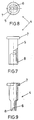
- Figure 5 is a side raised view of what is shown in figure 2.
- Figure 6 is a section along cutting line C of figure 5.
- Figures 7, 8 and 9 are respective raised views with a sectioned side raised portion with a sectioned quadrant and bottom plan, of one of the rotation bushings.
- the reinforcement piece applicable to refrigerator doors of the invention has a general prismatic shape with a triangular base and is made of injected plastic material. Its geometry can be seen in figures 1 to 6.
- the base of this prismatic shape is a right-angled triangle whose side surface (1) corresponding to the hypotenuse is the one that is to be parallel to the edge corresponding to the edge of the door, this edge being determined by the folded edges of the metal panel that the refrigerator door is made out of.
- This surface (1) forms a perimetric wing (2) that slightly exceeds the prismatic volume, this wing also having a, beveled edge in order to facilitate pressure contact by the thrust that the expansion of the insulating material that is injected in the door produces, once the metal panel receives the plastic inner portion of the door.
- the reinforcement piece includes a pair of identical generally cylinder-shaped recesses (3).
- a rotation bushing generally referred to as number (4) can be mounted.
- the design geometry thereof can be seen in figures 7 to 9.
- the shaft or pin of the corresponding hinge moves.
- the rotation bushing (4) is selectively inserted into either one of the recesses (3).
- Each one of the recesses (3) of the reinforcement piece has a first cylindrical portion and towards the inside they are finished in a flat portion in order to define antirotation means for the bushing (4) comprising a cylindric portion (5) and another flattened one (6) with sections equivalent to those of recess (3).
- the cylindric portion (5) of the rotation bushing (4) extends into a flange (7) and the free end of the narrow portion (6) has a diametric notch (8).
- the recesses (3) as clearly seen in figure 2, also open towards one of the side walls (9) of the former general prismatic-triangular shape according to longitudinal grooves (10) flanked by partition walls (11).
- the longitudinal partition walls (11) are joined by the end corresponding to the closed bottom (12) of the recess (3), while they are separated at the other end and form an opening at the bottom part of figure 2.
- the rotation bushing (4) is introduced through the hole (4) made in the edge of the door, in correspondence with the recess (3) and though the inside edge reaches the bottom (12) of the recess, there is a radial or side passage due to a lateral notch (8).
- the notch (8) is diametric so that the rotation bushing (4) can be inserted in any position.
Landscapes
- Engineering & Computer Science (AREA)
- Mechanical Engineering (AREA)
- General Engineering & Computer Science (AREA)
- Combustion & Propulsion (AREA)
- Physics & Mathematics (AREA)
- Thermal Sciences (AREA)
- Chemical & Material Sciences (AREA)
- Civil Engineering (AREA)
- Structural Engineering (AREA)
- Refrigerator Housings (AREA)
- Pharmaceuticals Containing Other Organic And Inorganic Compounds (AREA)
- Diaphragms For Electromechanical Transducers (AREA)
- Devices That Are Associated With Refrigeration Equipment (AREA)
- Defrosting Systems (AREA)
Abstract
Description
- The present invention refers to a reinforcement piece applicable to refrigerator doors, which has been conceived and developed for placement in the inside corners of refrigerator doors, to a reinforcement assembly including such a reinforcement piece, and to a refrigerator door including such a reinforcement piece.
- In the manufacturing process of refrigerator doors, one starts with a metal panel that has its edges folded over for the purpose of forming a type of open box in which the plastic inside portion of the door is incorporated. Between the panel of the door and -the plastic inside portion of the door there is an injected insulating material.
- Since the edges of the metal panel, in this part of the corners of the door, are not joined in a leak-proof manner, in the injection of the insulating material this material inevitably passes through the slots that remain and subsequently this material must be removed.
- Besides, the rotation axis of the hinges presently has problems of assembly since it is possible that it does not remain centered enough since the injected material offers resistance, when this rotation axis is incorporated in the door.
- The injected material also comes out through this area as the drilled holes of the panel through which the rotation axes of the hinges protrude are not plugged up adequately.
- A refrigerator door of the aforementioned type is disclosed in US-Patent No. 4,238,908 disclosing a front panel being first folded backwards to form the side portions and further folded to form a rear open frame whereby a plastic material closure is fitted within said frame. Openings are provided within the upper and lower portions of the door to house vertically inserted bushings secured to a horizontal hinge arm by means of a screw which is screwed through a hole in said arm into said bushing. Supplementary reinforcement plates, corner pieces and washers must be provided to provide resistance against wear out of the fitting of the bushing in the door whereby, when the space between the front panel and the plastic rear cover of the door is injected with insulating material, said material passes through the slots in the corners and, if the bushing has not been installed prior to injection, it leaks through the openings provided for the bushings and may offer resistance to subsequent insertion of the bushings whilst, if the bushings have been installed prior to injecting the insulating material, due to its great pressure it may push said bushing out of its vertical centered position thereby causing problems if not rendering correct hinging impossible.
- The reinforcement piece permits in the first place, plugging the slots of the corners for the purpose of preventing the injected material from coming through. Secondly, it also resolves the problem of guiding of the axis of the hinge,so that offcentering is not produced. It also prevents the insulating material to come out through the holes provided for said hinge shafts to come out through. A refrigerator door may have four reinforcement pieces, one in each corner and incorporated at the inner surface of the metal panel, before assemblying the plastic inner portion of the door. Only two of these reinforcement pieces are used to assemble the hinge shafts, depending on whether the door opens to the left or to the right.
- Each of these reinforcement pieces has two recesses whereby only one of both receives a rotation bushing of the shaft of the respective hinge. The rotation bushing will be inserted in either recess depending on whether the door opens to the left or to the right, as well as whether it belongs to a reinforcement piece at a top or bottom corner of the door.
- In order to facilitate the understanding of the features of the invention and forming an integral part of this specification, drawings, in whose figures, with an illustrative non-restrictive character the following has been represented, are attached hereto:
- Figure 1 is a bottom plan view of the reinforcement piece applicable to refrigerator doors, object of the invention.
- Figure 2 is a section along cutting line A-A of figure 1.
- Figure 3 is a top plan view of what is shown in the above cited figures.
- Figure 4 is a section along the cutting line B of figure 2.
- Figure 5 is a side raised view of what is shown in figure 2.
- Figure 6 is a section along cutting line C of figure 5.
- Figures 7, 8 and 9 are respective raised views with a sectioned side raised portion with a sectioned quadrant and bottom plan, of one of the rotation bushings.
- With reference to the numbering indicated in the figures, the reinforcement piece applicable to refrigerator doors of the invention has a general prismatic shape with a triangular base and is made of injected plastic material. Its geometry can be seen in figures 1 to 6. The base of this prismatic shape is a right-angled triangle whose side surface (1) corresponding to the hypotenuse is the one that is to be parallel to the edge corresponding to the edge of the door, this edge being determined by the folded edges of the metal panel that the refrigerator door is made out of. This surface (1) forms a perimetric wing (2) that slightly exceeds the prismatic volume, this wing also having a, beveled edge in order to facilitate pressure contact by the thrust that the expansion of the insulating material that is injected in the door produces, once the metal panel receives the plastic inner portion of the door.
- The reinforcement piece includes a pair of identical generally cylinder-shaped recesses (3). In each one of them a rotation bushing generally referred to as number (4) can be mounted. The design geometry thereof can be seen in figures 7 to 9. In the inside of this rotation bushing (4) the shaft or pin of the corresponding hinge moves. Depending on whether the opening of the door is to the left or to the right, as well as whether the reinforcement piece is at the top or bottom of the hinging shaft of the door, the rotation bushing (4) is selectively inserted into either one of the recesses (3).
- Each one of the recesses (3) of the reinforcement piece has a first cylindrical portion and towards the inside they are finished in a flat portion in order to define antirotation means for the bushing (4) comprising a cylindric portion (5) and another flattened one (6) with sections equivalent to those of recess (3). The cylindric portion (5) of the rotation bushing (4) extends into a flange (7) and the free end of the narrow portion (6) has a diametric notch (8).
- The recesses (3), as clearly seen in figure 2, also open towards one of the side walls (9) of the former general prismatic-triangular shape according to longitudinal grooves (10) flanked by partition walls (11). The longitudinal partition walls (11) are joined by the end corresponding to the closed bottom (12) of the recess (3), while they are separated at the other end and form an opening at the bottom part of figure 2.
- Upon effecting the assembly of the door, the bottom walls (12) corresponding to the recesses (3) without a rotation bushing (4) and only in the reinforcement pieces at the side of the hinging, are pierced through, operation which is easy since this wall (12) is very thin for this purpose, defining an easily removeable membrane.
- Since the recesses (3) of a single reinforcement piece are joined, if one of them is used to insert the rotation bushing (4), in which case the reinforcement piece would be located at the hinging side of the refrigerator door, in the injecting process of the insulating material upon the foam increasing in volume, an air outlet is produced precisely by the hole formed upon piercing through the membrane (12), from the free recess (3) without a rotation bushing (4) towards the enclosure formed by the piece and the walls of the door and from there to the recess (3) occupied by said bushing (4) and since the latter is of a tubular structure, by its axial recess (3) the air that the injected insulating material vacates comes out, without the injected material coming out, since the foam acquires enough consistency before coming outside.
- The rotation bushing (4) is introduced through the hole (4) made in the edge of the door, in correspondence with the recess (3) and though the inside edge reaches the bottom (12) of the recess, there is a radial or side passage due to a lateral notch (8). The notch (8) is diametric so that the rotation bushing (4) can be inserted in any position.
Claims (6)
- Reinforcement piece for hinging doors to a refrigerator body and sealing the corner portions of the doors, said refrigerator doors comprising- a metal panel forming the outside wall of the door and having folded edges to form the side portions and the perimetral inner walls forming a framework at the rear of the door;- a plastic material inner portion received in the opening defined by said inner walls;- insulating material placed between said panel and said inner portion by injection;- and at least two holes respectively provided in the side portions of said panel, substantially in the proximity of at least two of the four corners of said door;said reinforcement piece including means for receiving a rotation bushing (4) to allow rotatable housing of a substantially vertical shaft of a hinge of said refrigerator body;
characterized in that
the reinforcement piece comprises- a body having substantially the general shape of a right-angled triangle base prisma, the surface (1) corresponding to the hypotenuse defining a perimetric wing (2) that slightly exceeds the prismatic volume and which permits the reinforcement piece to be fixed to a corner of the door by means of pressure;- two recesses (3) extending through said body substantially orthogonally from one of its other surfaces towards the surface (1) corresponding to the hypotenuse, said recesses serving for the selective coupling of said rotation bushing (4) which allows rotatable housing of a substantially vertical shaft of a hinge of said refrigerator body, depending on whether the door opens to the right or to the left. - A reinforcement piece according to claim 1, characterized in that each one of said recesses (3) comprises a first substantially cylindrical portion which, by a stepped transition portion, extends into an inner narrower flattened end portion.
- A reinforcement piece according to any of claims 1 and 2, characterized in that the bottom end (12) of said recesses (3) (3) is removable or breakable.
- A reinforcement assembly including a reinforcement piece according to claim 2 or 3,
characterized in that
it further includes a bushing (4), where said bushing (4) is shaped in a substantially equivalent manner to said recesses(3) such that it comprises a first flange portion (7) having a wider perimeter than said first portion of said recesses (3) and emerging therefrom through one of said holes of said side portions of said panel, a second portion (5) having a perimeter substantially complementary to said cylindrical portion of said recesses (3), a third portion having a perimeter being substantially complementary to said transition portion of said recesses (3), and a fourth portion (6) having a perimeter being substantially complementary to said end portion, each recess (3) having at least one lateral window (10) extending between partition walls (11) into a face portion (9) of said prisma being substantially parallel to said recess (3), whereby said bushing (4) has a lateral notch (8) at its fourth portion (6) in a position communicating with said window (10), and whereby the windows (10) of said recesses (3) are communicated with each other by a passage provided substantially in said body of the reinforcement piece. - A refrigerator door with a reinforcement piece placed in at least two of its four corners, between the folded edges of a metal panel that forms the outside of the door and a plastic inner portion of the door that is received between said edges, the inside of the door being filled with an injected insulating material, said pieces establishing the sealing of the openings formed between said folded edges of the metal panel and carrying the door hinges,
characterized in that
each reinforcement piece has a general prismatic form with a right-angled triangle base whose larger surface (1), corresponding to the hypotenuse, defines a perimetric wing (2) that slightly exceeds the prismatic volume and which is applied under pressure against the edges of the panel, each reinforcement piece also including two recesses (3) for selective coupling of a rotation bushing (4) in which a hinge shaft can be housed, depending on whether the door opens to the right or to the left. - A refrigerator door according to claim 5, characterized in that each one of said recesses (3) comprises a first substantially cylindrical portion which, by a stepped transition portion, extends into an inner narrower flattened end portion.
Applications Claiming Priority (3)
| Application Number | Priority Date | Filing Date | Title |
|---|---|---|---|
| ES19919100814U ES1017002Y (en) | 1991-03-18 | 1991-03-18 | REINFORCEMENT PIECE APPLICABLE TO REFRIGERATOR DOORS. |
| ES9100814 | 1991-03-18 | ||
| PCT/ES1992/000027 WO1992016804A1 (en) | 1991-03-18 | 1992-03-18 | Reinforcement part applicable to refrigerator doors |
Publications (2)
| Publication Number | Publication Date |
|---|---|
| EP0531494A1 EP0531494A1 (en) | 1993-03-17 |
| EP0531494B1 true EP0531494B1 (en) | 1996-05-15 |
Family
ID=8271878
Family Applications (1)
| Application Number | Title | Priority Date | Filing Date |
|---|---|---|---|
| EP92907521A Expired - Lifetime EP0531494B1 (en) | 1991-03-18 | 1992-03-18 | Reinforcement piece for a refrigerator door and refrigerator door with such a reinforcement piece |
Country Status (18)
| Country | Link |
|---|---|
| EP (1) | EP0531494B1 (en) |
| AT (1) | ATE138186T1 (en) |
| BG (1) | BG61239B1 (en) |
| CZ (1) | CZ279198B6 (en) |
| DE (1) | DE69210722T2 (en) |
| ES (2) | ES1017002Y (en) |
| FI (1) | FI100208B (en) |
| HR (1) | HRP921190A2 (en) |
| HU (1) | HU215058B (en) |
| NO (1) | NO175793C (en) |
| PL (1) | PL168047B1 (en) |
| PT (1) | PT8956U (en) |
| RO (1) | RO114925B1 (en) |
| RU (1) | RU2066025C1 (en) |
| SI (1) | SI9210275A (en) |
| SK (1) | SK340592A3 (en) |
| WO (1) | WO1992016804A1 (en) |
| YU (1) | YU48259B (en) |
Family Cites Families (7)
| Publication number | Priority date | Publication date | Assignee | Title |
|---|---|---|---|---|
| US3107758A (en) * | 1960-06-24 | 1963-10-22 | Sanymetal Products Company Inc | Door structures and hinge assemblies |
| US3766599A (en) * | 1971-07-30 | 1973-10-23 | Mullins Mf Co | Button hinge |
| US3863391A (en) * | 1973-12-10 | 1975-02-04 | Gen Electric | Reversibly mounted cabinet door |
| DE7511148U (en) * | 1975-04-09 | 1975-08-14 | Licentia Patent Verwaltungs Gmbh | Fridge door framed with a frame |
| GB1602440A (en) * | 1977-08-16 | 1981-11-11 | Kelvinator Ltd | Formed metal panels |
| DE7820307U1 (en) * | 1978-07-06 | 1978-10-12 | Oni-Metallwarenfabriken Guenter & Co, 4973 Vlotho | ROTARY DOOR FOR A SHOWER CABIN |
| AU527287B2 (en) * | 1978-09-07 | 1983-02-24 | Fisher & Paykel Limited | Joining member |
-
1991
- 1991-03-18 ES ES19919100814U patent/ES1017002Y/en not_active Expired - Lifetime
-
1992
- 1992-03-18 WO PCT/ES1992/000027 patent/WO1992016804A1/en active IP Right Grant
- 1992-03-18 SI SI9210275A patent/SI9210275A/en unknown
- 1992-03-18 DE DE69210722T patent/DE69210722T2/en not_active Expired - Fee Related
- 1992-03-18 RU RU9292016406A patent/RU2066025C1/en active
- 1992-03-18 EP EP92907521A patent/EP0531494B1/en not_active Expired - Lifetime
- 1992-03-18 YU YU27592A patent/YU48259B/en unknown
- 1992-03-18 PL PL92296924A patent/PL168047B1/en unknown
- 1992-03-18 ES ES92907521T patent/ES2090621T3/en not_active Expired - Lifetime
- 1992-03-18 RO RO92-01441A patent/RO114925B1/en unknown
- 1992-03-18 SK SK3405-92A patent/SK340592A3/en unknown
- 1992-03-18 AT AT92907521T patent/ATE138186T1/en active
- 1992-03-18 HU HU9203596A patent/HU215058B/en not_active IP Right Cessation
- 1992-11-04 HR HRP921190AA patent/HRP921190A2/en not_active Application Discontinuation
- 1992-11-17 NO NO924427A patent/NO175793C/en unknown
- 1992-11-17 BG BG97093A patent/BG61239B1/en unknown
- 1992-11-17 FI FI925213A patent/FI100208B/en active
- 1992-11-17 CZ CZ923405A patent/CZ279198B6/en unknown
-
1993
- 1993-12-15 PT PT8956U patent/PT8956U/en not_active IP Right Cessation
Also Published As
| Publication number | Publication date |
|---|---|
| HU9203596D0 (en) | 1993-04-28 |
| SI9210275A (en) | 1995-10-31 |
| ES1017002U (en) | 1991-12-16 |
| RO114925B1 (en) | 1999-08-30 |
| WO1992016804A1 (en) | 1992-10-01 |
| NO175793B (en) | 1994-08-29 |
| ES2090621T3 (en) | 1996-10-16 |
| ES1017002Y (en) | 1992-06-16 |
| FI100208B (en) | 1997-10-15 |
| FI925213A0 (en) | 1992-11-17 |
| NO175793C (en) | 1994-12-07 |
| DE69210722D1 (en) | 1996-06-20 |
| HUT63921A (en) | 1993-10-28 |
| HRP921190A2 (en) | 1995-02-28 |
| HU215058B (en) | 1998-09-28 |
| BG61239B1 (en) | 1997-03-31 |
| ATE138186T1 (en) | 1996-06-15 |
| CZ340592A3 (en) | 1993-10-13 |
| NO924427L (en) | 1993-01-07 |
| EP0531494A1 (en) | 1993-03-17 |
| PL296924A1 (en) | 1993-10-18 |
| NO924427D0 (en) | 1992-11-17 |
| YU48259B (en) | 1997-09-30 |
| RU2066025C1 (en) | 1996-08-27 |
| CZ279198B6 (en) | 1995-01-18 |
| YU27592A (en) | 1995-10-03 |
| PL168047B1 (en) | 1995-12-30 |
| SK340592A3 (en) | 1994-04-06 |
| PT8956T (en) | 1994-05-31 |
| FI925213A (en) | 1992-11-17 |
| PT8956U (en) | 1998-01-30 |
| DE69210722T2 (en) | 1996-12-19 |
Similar Documents
| Publication | Publication Date | Title |
|---|---|---|
| US5211502A (en) | Connection system | |
| JP4219042B2 (en) | Switchboard cabinet | |
| US20030145532A1 (en) | One-piece injection molded window frame and sash | |
| JP2787714B2 (en) | Cabinet with folding door | |
| US20020020124A1 (en) | Hinged door inner frame and door structure for which the inner frame is used | |
| EP0531494B1 (en) | Reinforcement piece for a refrigerator door and refrigerator door with such a reinforcement piece | |
| US4218848A (en) | Plastic foam-filled door having integral plastic housing defining lock cylinder and lock bolt chambers | |
| FI81877B (en) | ANORDNING VID DOERRAR. | |
| CN214498729U (en) | Adjustable hinge assembly and corresponding opening and closing device | |
| CN216110381U (en) | Multi-functional bight connecting piece of expandable formula | |
| EP2224089B1 (en) | Method for making a corner joint and corner piece applied thereby | |
| JPS6341485Y2 (en) | ||
| KR0176686B1 (en) | Refrigerator having a separatable hinge bracket plate | |
| KR200289558Y1 (en) | Air conditioner with control panel | |
| JPS647183Y2 (en) | ||
| JPH108852A (en) | Airtight structure for hinged door | |
| JP2000041310A (en) | Control box |
Legal Events
| Date | Code | Title | Description |
|---|---|---|---|
| PUAI | Public reference made under article 153(3) epc to a published international application that has entered the european phase |
Free format text: ORIGINAL CODE: 0009012 |
|
| AK | Designated contracting states |
Kind code of ref document: A1 Designated state(s): AT BE CH DE DK ES FR GB GR IT LI LU MC NL SE |
|
| RAP1 | Party data changed (applicant data changed or rights of an application transferred) |
Owner name: BS ELECTRODOMESTICOS, S.A. |
|
| 17P | Request for examination filed |
Effective date: 19921123 |
|
| 17Q | First examination report despatched |
Effective date: 19940421 |
|
| GRAH | Despatch of communication of intention to grant a patent |
Free format text: ORIGINAL CODE: EPIDOS IGRA |
|
| GRAA | (expected) grant |
Free format text: ORIGINAL CODE: 0009210 |
|
| AK | Designated contracting states |
Kind code of ref document: B1 Designated state(s): AT BE CH DE DK ES FR GB GR IT LI LU MC NL SE |
|
| PG25 | Lapsed in a contracting state [announced via postgrant information from national office to epo] |
Ref country code: NL Free format text: LAPSE BECAUSE OF FAILURE TO SUBMIT A TRANSLATION OF THE DESCRIPTION OR TO PAY THE FEE WITHIN THE PRESCRIBED TIME-LIMIT Effective date: 19960515 Ref country code: LI Effective date: 19960515 Ref country code: GR Free format text: LAPSE BECAUSE OF FAILURE TO SUBMIT A TRANSLATION OF THE DESCRIPTION OR TO PAY THE FEE WITHIN THE PRESCRIBED TIME-LIMIT Effective date: 19960515 Ref country code: DK Effective date: 19960515 Ref country code: CH Effective date: 19960515 Ref country code: BE Effective date: 19960515 Ref country code: AT Effective date: 19960515 |
|
| REF | Corresponds to: |
Ref document number: 138186 Country of ref document: AT Date of ref document: 19960615 Kind code of ref document: T |
|
| REF | Corresponds to: |
Ref document number: 69210722 Country of ref document: DE Date of ref document: 19960620 |
|
| ITF | It: translation for a ep patent filed |
Owner name: BARZANO' E ZANARDO ROMA S.P.A. |
|
| ET | Fr: translation filed | ||
| REG | Reference to a national code |
Ref country code: ES Ref legal event code: FG2A Ref document number: 2090621 Country of ref document: ES Kind code of ref document: T3 |
|
| NLV1 | Nl: lapsed or annulled due to failure to fulfill the requirements of art. 29p and 29m of the patents act | ||
| REG | Reference to a national code |
Ref country code: CH Ref legal event code: PL |
|
| REG | Reference to a national code |
Ref country code: ES Ref legal event code: FG2A Ref document number: 2090621 Country of ref document: ES Kind code of ref document: T3 |
|
| PLBE | No opposition filed within time limit |
Free format text: ORIGINAL CODE: 0009261 |
|
| STAA | Information on the status of an ep patent application or granted ep patent |
Free format text: STATUS: NO OPPOSITION FILED WITHIN TIME LIMIT |
|
| PG25 | Lapsed in a contracting state [announced via postgrant information from national office to epo] |
Ref country code: LU Free format text: LAPSE BECAUSE OF NON-PAYMENT OF DUE FEES Effective date: 19970331 |
|
| 26N | No opposition filed | ||
| PG25 | Lapsed in a contracting state [announced via postgrant information from national office to epo] |
Ref country code: MC Effective date: 19970930 |
|
| REG | Reference to a national code |
Ref country code: FR Ref legal event code: CD |
|
| REG | Reference to a national code |
Ref country code: GB Ref legal event code: IF02 |
|
| PGFP | Annual fee paid to national office [announced via postgrant information from national office to epo] |
Ref country code: SE Payment date: 20020221 Year of fee payment: 11 |
|
| PGFP | Annual fee paid to national office [announced via postgrant information from national office to epo] |
Ref country code: FR Payment date: 20020227 Year of fee payment: 11 |
|
| PGFP | Annual fee paid to national office [announced via postgrant information from national office to epo] |
Ref country code: GB Payment date: 20020320 Year of fee payment: 11 |
|
| PGFP | Annual fee paid to national office [announced via postgrant information from national office to epo] |
Ref country code: DE Payment date: 20020429 Year of fee payment: 11 |
|
| PG25 | Lapsed in a contracting state [announced via postgrant information from national office to epo] |
Ref country code: GB Free format text: LAPSE BECAUSE OF NON-PAYMENT OF DUE FEES Effective date: 20030318 |
|
| PG25 | Lapsed in a contracting state [announced via postgrant information from national office to epo] |
Ref country code: SE Free format text: LAPSE BECAUSE OF NON-PAYMENT OF DUE FEES Effective date: 20030319 |
|
| PG25 | Lapsed in a contracting state [announced via postgrant information from national office to epo] |
Ref country code: DE Free format text: LAPSE BECAUSE OF NON-PAYMENT OF DUE FEES Effective date: 20031001 |
|
| EUG | Se: european patent has lapsed | ||
| GBPC | Gb: european patent ceased through non-payment of renewal fee |
Effective date: 20030318 |
|
| PG25 | Lapsed in a contracting state [announced via postgrant information from national office to epo] |
Ref country code: FR Free format text: LAPSE BECAUSE OF NON-PAYMENT OF DUE FEES Effective date: 20031127 |
|
| REG | Reference to a national code |
Ref country code: FR Ref legal event code: ST |
|
| PG25 | Lapsed in a contracting state [announced via postgrant information from national office to epo] |
Ref country code: IT Free format text: LAPSE BECAUSE OF NON-PAYMENT OF DUE FEES;WARNING: LAPSES OF ITALIAN PATENTS WITH EFFECTIVE DATE BEFORE 2007 MAY HAVE OCCURRED AT ANY TIME BEFORE 2007. THE CORRECT EFFECTIVE DATE MAY BE DIFFERENT FROM THE ONE RECORDED. Effective date: 20050318 |
|
| PGFP | Annual fee paid to national office [announced via postgrant information from national office to epo] |
Ref country code: ES Payment date: 20070419 Year of fee payment: 16 |
|
| REG | Reference to a national code |
Ref country code: ES Ref legal event code: FD2A Effective date: 20080319 |
|
| PG25 | Lapsed in a contracting state [announced via postgrant information from national office to epo] |
Ref country code: ES Free format text: LAPSE BECAUSE OF NON-PAYMENT OF DUE FEES Effective date: 20080319 |