EP0530845A2 - Die support arrangement in a rotary forming apparatus - Google Patents
Die support arrangement in a rotary forming apparatus Download PDFInfo
- Publication number
- EP0530845A2 EP0530845A2 EP19920115657 EP92115657A EP0530845A2 EP 0530845 A2 EP0530845 A2 EP 0530845A2 EP 19920115657 EP19920115657 EP 19920115657 EP 92115657 A EP92115657 A EP 92115657A EP 0530845 A2 EP0530845 A2 EP 0530845A2
- Authority
- EP
- European Patent Office
- Prior art keywords
- die
- die support
- block
- leading
- trailing
- Prior art date
- Legal status (The legal status is an assumption and is not a legal conclusion. Google has not performed a legal analysis and makes no representation as to the accuracy of the status listed.)
- Granted
Links
Images


Classifications
-
- B—PERFORMING OPERATIONS; TRANSPORTING
- B21—MECHANICAL METAL-WORKING WITHOUT ESSENTIALLY REMOVING MATERIAL; PUNCHING METAL
- B21D—WORKING OR PROCESSING OF SHEET METAL OR METAL TUBES, RODS OR PROFILES WITHOUT ESSENTIALLY REMOVING MATERIAL; PUNCHING METAL
- B21D28/00—Shaping by press-cutting; Perforating
- B21D28/24—Perforating, i.e. punching holes
- B21D28/36—Perforating, i.e. punching holes using rotatable work or tool holders
-
- Y—GENERAL TAGGING OF NEW TECHNOLOGICAL DEVELOPMENTS; GENERAL TAGGING OF CROSS-SECTIONAL TECHNOLOGIES SPANNING OVER SEVERAL SECTIONS OF THE IPC; TECHNICAL SUBJECTS COVERED BY FORMER USPC CROSS-REFERENCE ART COLLECTIONS [XRACs] AND DIGESTS
- Y10—TECHNICAL SUBJECTS COVERED BY FORMER USPC
- Y10T—TECHNICAL SUBJECTS COVERED BY FORMER US CLASSIFICATION
- Y10T83/00—Cutting
- Y10T83/465—Cutting motion of tool has component in direction of moving work
- Y10T83/4766—Orbital motion of cutting blade
- Y10T83/4795—Rotary tool
- Y10T83/4812—Compound movement of tool during tool cycle
Definitions
- This invention relates to a rotary cutting and forming apparatus for high speed continuous punching, forming or shearing of sheet metal.
- Conventional sheet metal cutting and forming devices are reciprocating presses. Material to be worked is placed within a press, positioned stationary over a die. The press, usually mechanically operated, is closed, thus forcing a second die into contact with the workpiece. The force exerted on the workpiece by the dies will deform the piece or punch holes in the piece as requird. When the operation is completed the press opens, the workpiece is removed and a new workpiece inserted. Because of the reciprocating motion inherent in such devices, the speed with which they may work is limited. Two solutions have been used. In one system the strip material is moved intermittently, step-wise through the press. In another system a so-called flying shear or die is used with a strip moving continuously.
- the die is accelerated to the speed of the strip and the press closes, while the die and strip are moving in unison.
- the die then opens, and returns to its starting position.
- the punching, forming or shearing of a continuous material, such as sheet metal is limited to a line speed of about 250 feet per minute.
- a roll forming line without a punching, forming or shearing device could handle strip metal at speeds up to about 1,000 feet per minute.
- Such devices are generally designed to perform a specific one of the above operations and may not be able to perform other operations. In particular, they are unable to meet all the requirements for a full range of die forming operations, or for shearing a strip already formed into a complex section.
- the invention provides for a high speed rotary cutting and forming apparatus which makes use of flat dies and permits the accuracy of conventional die presses.
- apparatus for rotary cutting and forming comprises rotary cutting and forming apparatus comprising material forming dies for forming strip material comprising a rotatable upper roll unit and a corresponding rotatable lower roll unit, said units being connected for synchronous rotation, each of said units comprising a carrier member defining a central axis, said member having at least one recess extending along said member parallel to the central axis, said recess having bearing surface means of generally semi-circular shape and at least one die support block rotatably received within said recess, said block defining two ends and a platen surface to which at least one of said forming dies may be affixed, said upper and lower units being spaced apart whereby said material may pass therebetween for formation by said dies cam surface means provided on a stationary part in association with each of said rollers and means effective between said cam surface means at each said die support block for turning said blocks about their axes which are parallel to the roll axes in said recesses and relative to said roll units so that the
- the device can be operated continuously or intermittently at high speed, thus allowing a manufacturing line, in which the device may be a component, to operate at high line speed.
- the device is as accurate as conventional, reciprocating die presses. use of a flat die set allows standard die tool-making procedures to be used.
- the device may have as much flexibility in its use, for forming holes, indentations and the like in a workpiece, as has a conventional die press.
- FIG. 1 there is illustrated a roll 10 of strip sheet material 12 upon which it is desired to perform various forming operations.
- Material 12 may often be sheet metal. Such operations may typically be performed in a manufacturing line 14.
- Material 12 is unwound from roll 10 and passed continuously along line 14, in the direction indicated by arrow A.
- the various forming operations are performed on material 12 as it passes different points along line 14.
- typical first operations may be die forming operations, performed by a rotary apparatus 20 according to the invention.
- Apparatus 20 may punch holes, or form complex indentations 22, or both, in material 12 as it passes through apparatus 20.
- Subsequent operations may typically include roll-forming operations at station 23. Further operations as desired may be carrid out at station 24.
- the final operation is typically the cutting of material 12 in cutting station 26 into standard lengths 28 convenient for further manufacturing or assembly processes and for storage.
- nip rollers may be used to guide material 12 through stations 23, 24 and 26.
- stations 23, 24 and 26 may be used in sequence, as desired.
- Motor 30 drives upper roll unit 32 in unison with and, at the same speed, as lower roll unit 34 through transmission 35 and shafts 36.
- Material 12 passes between and is contacted by upper and lower units 32 and 34.
- Upper and lower units 32 and 34 may be supported by suitable bearing means 37.
- motor 30 and transmission 35 are such as to provide the outer surfaces of upper and lower units 32 and 34 at the point of contact with material 12 with essentially the same speed as material 12, so that there is no slippage or relative motion between the material 12 and either or both of upper unit 32 and lower unit 34.
- Transmission 35 and bearings 37 may be adjustable to vary the maximum distance between upper and lower units 32 and 34 in order to accommodate sheet material 12 of varying thicknesses or to increase the pressure applied to material 12.
- Hydraulic pistons 40 may be attached to shafts 36 so that upper unit 32 may be quickly removedfrom contact with material 12. Such capability allows the apparatus 20 to leave linear portions of material 12 unformed, if desired.
- Motor 30, transmission 35, bearings 37 and pistons 40 may all be standard components as are well-known in the machine tooling industry.
- Figure 3 illustrates in cross-section upper die unit 32 and lower die unit 34 in position to die form sheet material 12.
- Upper unit 32 rotates counter-clockwise in the direction indicated by arrow B.
- Lower unit 34 rotates clockwise in the direction indicated by arrow C.
- Material 12 moves from left to right in the direction indicated by arrow A.
- Upper unit 32 is essentially identical to lower unit 34.
- upper unit 32 includes upper carrier member 41, which defines a longitudinal axis L1 about which upper unit 32 rotates.
- Member 41 defines at least one (in the illustrated :embodiment, there are four) generally semi-circular cylindrical recesses on opening 42, defining central axes ( Figure 5) extending longitudinally parallel to the axis L1 of member 41.
- Member 41 further defines abutments 43 between openings 42.
- the outer surface of abutments 43 define a notional circular cylindrical surface 44 (shown in cross-section as phantom circle 44).
- the axes L2 of cylindrical openings 42 may lie on notional surface 44 parallel to axis L1. However in an alternate embodiment described below this is modified.
- upper die support blocks 46 are retained within openings 42 by the semi-circular retaining flanges 47.
- Each block 46 is semi-cylindrical in shape having a cross-section that is segment-shaped namely, that shape bounded between the perimeter of a circle and a chord of the circle.
- block 46 defines two surface portions: a semi-cylindrical portion 46a and a planar portion 46b.
- Semi-cylindrical portion 46a is fitted within opening 42, so that block 46 is freely rotatable within its associated opening 42.
- a first guide pin means 48 extends from one end of blocks 46 and a second guide pin means 49 extends from the outer end guide blocks 46, and ensure that the planar portions 4gb are located in the desired position as described below.
- pin means 48 and 49 define and lie on different axes for reasons described below.
- Upper dies 50 are mounted on planar portions 46b of blocks 46 in any conventional manner.
- the die surface of a die 50 defines a forming plane P2 ( Figure 5).
- Die 50 is mounted on block 46 so that the plane P2 is essentially parallel to the planar portion 46b of block 46 and so that the plane P2 includes the axis of opening 42, in this embodiment
- Lower unit 34 comprises lower carrier member 52, defining semi cylindrical openings 54, abutments 55 and semi-cylindrical surface 56, lower support blocks 58, and flat lower dies 60.
- Guide pin means 62 and 63 are provided in a fashion offset at opposite ends of the block similar to the equivalent components of upper unit 32. Retaining flanges 47 are also provided.
- pins 48, 49, 62 and 63 defines a cam follower means (not shown) at its free end.
- Pins 48 are guided by cam means such as a cam groove 64 defined in fixed end plate 38, at one end.
- Pins 49 are guided by cam means such as a cam groove 65 in fixed end plate 39, at the opposite end.
- guide pins 62 and 63 are guided by corresponding cam means; e.g., cam grooves 70 and 72, respectively, in fixed end plates 38 and 39, at opposite ends.
- Fixed end plate 38 is divided between grooves 64 and 70 into upper and lower end plates, 38a and 38b repectively.
- end plate 39 is split between grooves 66 and 72 into upper and lower end plates, 39a and 39b.
- Both end plates 38a and 39a are fixed by suitable means (not shown) relative to the axis L1 of upper unit 32.
- suitable means may, for example, comprise a guide track, preventing the rotation of plates 38a and 39a relative to axis L1, and a bearing means for shaft 36 in plates 38a and 39a.
- end plates 38b and 39b are fixed relative to the axis L1 of lower unit 34.
- split end plates 38a, 38b, 39a and 39b fixed as described above, allows the distance between upper unit 32 and lower unit 34 to be varied as desired without interfering with the operation of die forming apparatus 20.
- hydraulic cylinders 40 As hydraulic cylinders 40 are operated, such distance between units 32 and 34 varies.
- Upper end plates 38a and 39a move up and down in unison with upper unit 32, yet cam grooves 64 and 65 continue to support pins 48 and 49.
- Cam grooves 64 and 65 are shaped and pins 48 and 49 are positioned relative to blocks 46 whereby the forming planes P2 of dies 50 are essentially parallel to material 12 immediately prior to, during and subsequent to closing.
- cam grooves 70 and 72 are shaped, and pins 62 and 63 are positioned relative to blocks 58 whereby the forming planes P2 of dies 60 are essentially parallel to material 12 immediately prior to, during and subsequent to closing,
- a block 46 and a block 58 may each be supported by two pins on different axes the blocks are less prone to rock or otherwise move within their fittings than are those found in standard rotary forming devices.
- the clearances requird by the cam follower mechanism do not have as great an effect on the accuracy of the forming operation.
- the double cam construction of the invention results in substantially improved forming accuracy, and thus, longer useful die life.
- upper support block 46 may be provided with locating dowels 78 on either side of die 50 (see Figure 6).
- Lower support block 58 may be provided with corresponding dowel receiving bores 79 on either side of die 60.
- Dowels 78 and bores 79 are shaped, sized and located on either side of strip material 12 so that they may cooperate and register with each other without interference with material 12.
- dowels 78 extend toward and are partially inserted into bores 79 prior to contact with material 12.
- the dowels 78 are fully inserted into the bore 79, thus ensuring that die 50 and die 60 contact material 12 in proper registration with each other.
- dowels 78 and bores 79 Although accuracy is ensured by the use of dowels 78 and bores 79, such dowels 78 and bores 79 may not always be necessary for the accurate functioning of the device according to the invention.
- the device as described above has been found to operate with satisfactory accuracy without such dowels and bores.
- upper and lower units 32 and 34 rotate.
- Each die 50 rotates through the successive illustrated positions of upper unit 32.
- Such positions have been labelled in Figure 3 as positions S, U, W, and Y.
- the closed position of apparatus 20, which is the position at which material 12 is formed, is defined as position S.
- Position S is treated as defining the starting point of the rotary cycle. Rotation continues, counter-clockwise as indicated by direction arrow B, through each of the other positions U, W and Y and returns to starting position S.
- each die 60 rotates through the illustrated positions of lower unit 34.
- the movement of any die 60 is the mirror image of the movement of its corresponding die 50. It will, of course, be appreciated that all dies rotate simultaneously and, at any particular time, are at different positions in the rotary cycle.
- cam grooves defined in the fixed end plates 38 and 39 are not necessary. Instead the cam followers of pins 48, 49, 62 and 63 may be constrained to follow curved ramps during certain predetermined positions in the rotary cycle.
- ramp 80 is affixed to fixed end plate 38a and ramp 82 to fixed end plate 39a.
- ramps 84 and 86 are also affixed to fixed end plates 38b and 39b, respectively.
- Ramps 80, 82, 84 and 86 define curved surfaces 88, 90, 92 and 94, respectively.
- Surfaces 88, 90, 92 and 94 are shaped whereby the forming planes P2 of dies 50 and 60 are essentially parallel to material 12 and to each other immediately prior to, during and subsequent to closing. During other parts of the rotary cycle, the precise positioning of blocks 46 and 58 relative to members 41 and 52, respectively, are unimportant as long as blocks 46 and 58 may again be brought parallel prior to closing.
- Block 46 defines a circumferential channel 96.
- Member 41 has a post 98, adapted to fit within channel 96 so that block 46 may still orbit within opening 42.
- Spring 100 is fitted within channel 96 and attached at one end to a wall of channel 96 (or to a post inserted in channel 96) and at the other end to post 98. In such a configuration, spring 100 tends to hold block 46 in the position indicated as J or K in Figure 8 relative to member 41. In this position, pin 48 is extended radially away from axis L1 whereby it may come into contact with its respective ramp 80 at a predetermined position in the rotary cycle.
- Figure 7 illustrates upper and lower units 32 and 34 in a position immediately after one pair of dies 50 and 60 have closed and immediately before a second pair of dies 50 and 60 have closed.
- Figure 8 illustrates one block 46 in member 41 shown at various positions in the rotary cycle. Successive positions are indicated by the labels J, K, H, M, N and O.
- One ramp 80 and its associated pin 48 are drawn in sold line.
- the other ramp 82 and its associated pin 49 are shown in phantom.
- pin 48 contacts the surface 88 of ramp 80. Also, pin 49 contacts the surface 90 of ramp 82. As rotation continues block 46 now commences to orbit within opening 44. Spring 100 commences to stretch. Pin 48 moves along surface 88. Pin 49 moves along surface 90. Such motion continues to position M. The surfaces 88 and 90 are shaped to ensure that plane P2 remains parallel to material 12.
- a corresponding plane P2 of die 60 is also essentially parallel to material 12 and thus to the plane P2 of die 50.
- pin 49 which in this case is the leading pin, is removed from ramp 82.
- Suitable limit means allow spring 100 to hold block 46 within opening 42 during rotation from position J to position L.
- abutment means (not shown) extending into opening 42 from member 41 would allow spring 100 to hold block 46 securely against the abutment. Block 46 would thus be prevented from moving in its opening 42 under the influence of centrifugal force as unit 32 rotates.
- a ramp or cam groove on only one side of a die unit in conjunction with such a spring urging a die support block into contact with such ramp or groove. It may also be possible to use a ramp on one side of a die unit and a cam groove on the other side of the same unit. Use of a biasing spring may be avoided in such an embodiment.
- a die apparatus may be used in any situation requiring the use of high speed, accurate cutting or forming.
- the apparatus of the invention may, for instance, be used with a shearing die to cut roll formed strip material with a complex, shaped edge.
- a first rotary apparatus may punch a hole.
- a second rotary apparatus may form shapes around the hole.
- a third rotary apparatus may perform further operations and so on as required. Such operation would be very similar to the operation of existing progressive die presses.
- the apparatus of the invention may be used to leave unformed areas at spaced intervals along the strip material.
- the upper and lower units 32 and 34 are simply separated so that they do not contact material 12 over such intervals.
- the pins 78 and openings 79 will normally provide a sufficient degree of guidance to ensure that the two blocks are precisely parallel to one another before the dies close.
- the upper die block 46 is shown with the die guidance pin 78 received in a bore 102, and being retained therein by any suitable means (not shown).
- a die block guide channel 104 is machined in either end of the block 46, so as to replace the function of the retaining flanges 47, and is engaged by suitable retaining means (not shown) on carrier member 41.
- This feature would also be used in the blocks 58 in carrier member 52 in this embodiment.
- a further guide bore 108 is formed in, for example, the upper die block 46, parallel to the bore 102.
- Bore 108 communicates with a longitudinal channel 110 of generally rectangular shape, extending from side to side of the block 46 transverse to its longitudinal axis.
- Each of the die blocks 46 and 58 may be provided with two such guidance bores 108, one at each end, and two such channels 110.
- An elongated rectangular contact bar 112 is received in channel 110, and is mounted on a cylindrical guide shaft 114 extending into guide bore 108.
- a counter-bore 116 is formed in shaft 114, and receives a spring 118 therein.
- the spring 118 will preferably be a heavy duty compression spring.
- Any suitable retaining means (not shown) will be provided for retaining the shaft 114 in the bore 108.
- the four bars 112 on the upper and lower die members 26 and 58 register with one another in pairs, as the dies are closing, but prior to contact with the workpiece.
- the heavy duty springs 118 will yield and allow the bars 112 to move inwardly into the channels 110, but will, at the same time, force the faces of the bars 112 firmly into contact with one another along their length.
- This function will thus ensure that the blocks 46 and 58 are located in parallel spaced-apart planes parallel to the workpiece prior to contact of the dies with the workpiece, thus ensuring accurate repetitive forming of the workpiece, without damage to the dies.
- both the upper and lower die blocks 46 and 58 are provided with the same guidance bars 112 and shafts 116.
- the purpose of this is to reduce the distance of travel of each of the guide bars 112, and yet ensure that they meet and contact one another at a point early enough in the closing of the dies, that they can achieve a secure and accurate guidance function before the die is closed.
- the invention is not, therefore, limited to any specific number of such guidance bars.
- Intermittent operation may be desirable where it is intended to produce from the strip sheet material, an end product which is cut to a predetermined length.
- an end product which is cut to a predetermined length.
- a typical strip sheet material line for functioning in this way would comprise a rotary cutting or forming apparatus 120, upstream and downstream pinch rolls 122 and 124, and an uncoiler 126.
- the strip sheet material is indicated as 12, and in this embodiment is shown simply as being formed with generally triangular perforations or openings 12a.
- a discontinuity indicated generally as 12b is indicated between two of the perforations 12a.
- the rotary apparatus 120 is driven by means of a motor 128, driving through a clutch 130.
- Clutch 130 drives the rotary apparatus 120, and the drive is controlled by means of a brake 132.
- a line speed indicator 134 may be used if desired, for contacting the strip sheet material 12.
- this information can equally well be obtained in other ways, and it is illustrated here merely for the sake of clarity.
- a central data processing unit 136 provided with typical controls and displays is connected to the line speed indicator 134, and to the clutch 130 and to the brake 132.
- It may also be connected to all of the rolls, and to the motor 128 if desired for capturing further information.
- the rotary apparatus 120 is essentially similar to that described in the preceding description. Accordingly the various features are described in only general terms herein, where they are the same.
- the rotary apparatus 120 comprises carrier members 138 and 140 having die support blocks 142 and 144, guided and controlled in the manner described above.
- the central axis of the die blocks 142 and 144 move around a circular path, indicated in phantom as 146.
- the surface portions 148 and 150 of the carrier members 138 and 140 lie on the perimeter of a circle of a somewhat smaller radius than the circle 146.
- the workpiece is held in any event between the pinch rolls 122 and 124, and is therefore at all times controlled.
- the processor 136 will then again signal the brake 132 to release and the clutch 130 to re-engage, and rotation of the carrier members 138 and 140 will be resumed.
Abstract
Description
- This invention relates to a rotary cutting and forming apparatus for high speed continuous punching, forming or shearing of sheet metal.
- Conventional sheet metal cutting and forming devices are reciprocating presses. Material to be worked is placed within a press, positioned stationary over a die. The press, usually mechanically operated, is closed, thus forcing a second die into contact with the workpiece. The force exerted on the workpiece by the dies will deform the piece or punch holes in the piece as requird. When the operation is completed the press opens, the workpiece is removed and a new workpiece inserted. Because of the reciprocating motion inherent in such devices, the speed with which they may work is limited. Two solutions have been used. In one system the strip material is moved intermittently, step-wise through the press. In another system a so-called flying shear or die is used with a strip moving continuously. In this system the die is accelerated to the speed of the strip and the press closes, while the die and strip are moving in unison. The die then opens, and returns to its starting position. Typically, the punching, forming or shearing of a continuous material, such as sheet metal, is limited to a line speed of about 250 feet per minute.
- However, a roll forming line without a punching, forming or shearing device could handle strip metal at speeds up to about 1,000 feet per minute.
- It is evident that the output of an assembly or manufacturing line is only as fast as the slowest element in the line. In theory, a rotary press could be operated at much higher line speeds than a flying shear or die, and thus lead to considerable economies in operation.
- Existing rotary material-working devices may suffer from various disadvantages. Some may be limited to specific operations such as cutting (see United States Patent Nos. 2,951,410, 3,274,873, 3,438,835, 3,709,077 and 3,828,636); perforating (see United States Patent No. 3,205,744); embossing (see United States Patent Nos. 804,512 and 4,059,000, and United Kingdom Patent Nos. 837,660 and 1,456,530); crimping (see United States Patent Nos. 3,123,905 and 3,367,161); and stretch forming (see United States Patent No. 3,394,573).
- Such devices are generally designed to perform a specific one of the above operations and may not be able to perform other operations. In particular, they are unable to meet all the requirements for a full range of die forming operations, or for shearing a strip already formed into a complex section.
- In such existing rotary machines shearing is feasible on flat, unformed strip. Die forming was achieved by using specially designed dies sometimes formed around an arc, which severely restricted the shape that could be formed. Generally it was not possible to use conventional flat dies as used in conventional reciprocating presses. Dies formed around an arc or radius, such as in U.S. Patent 3,394,573, posed considerable problems. The function of a curved die as it contacts the workpiece is different from that of a flat die. The curved die will commence working the material on one side of the die. As the curved die rotates, deformation of the workpiece will proceed along the workpiece until the operation is complete. This often resulted in distortion. In a flat die as found in conventional die presses, the workpiece is cut or worked simultaneously across the die. In certain applications, such differences between standard and rotary devices may not be desirable.
- Another approach to the problem is shown in United States Patent Nos 1 333 704, 1 581 236 and 3 066 542. In these patents the dies rotate around a circular orbit.
- In United States Patent No 1 581 236, the individual dies are guided and controlled by an annular cam track, and cam followers riding in the track. In this arrangement the dies are oscillated or rocked, and are difficult to control. The cam followers cannot make a perfect fit in the annular track. Some clearance is needed in order that the followers can roll in the track. As a result, the dies are never held securely. When they meet they may fail to register perfectly, and damage may result.
- With a view to overcoming these problems, the invention provides for a high speed rotary cutting and forming apparatus which makes use of flat dies and permits the accuracy of conventional die presses.
- According to the invention apparatus for rotary cutting and forming comprises rotary cutting and forming apparatus comprising material forming dies for forming strip material comprising a rotatable upper roll unit and a corresponding rotatable lower roll unit, said units being connected for synchronous rotation, each of said units comprising a carrier member defining a central axis, said member having at least one recess extending along said member parallel to the central axis, said recess having bearing surface means of generally semi-circular shape and at least one die support block rotatably received within said recess, said block defining two ends and a platen surface to which at least one of said forming dies may be affixed, said upper and lower units being spaced apart whereby said material may pass therebetween for formation by said dies cam surface means provided on a stationary part in association with each of said rollers and means effective between said cam surface means at each said die support block for turning said blocks about their axes which are parallel to the roll axes in said recesses and relative to said roll units so that the said dies may be parallel to one another when adjacent to said material and cooperate together for deformation of the material characterised in that said means effective between the cam surface means and each die support block comprise leading and trailing control pin means extending from said block eccentrically of the axis of said block and respectively forwardly and rearwardly of said axis when the block is in the position adjacent said material, each of said control pins being associated with and engaging a corresponding and different one of the cam surface means (pin engaging cam pin engaging cam pin engaging cam and pin engaging cam whereby the said blocks are caused to rotate about their axes relative to the roll units as the latter rotate about their axes.
- The advantages of the invention include the following: the device can be operated continuously or intermittently at high speed, thus allowing a manufacturing line, in which the device may be a component, to operate at high line speed. The device is as accurate as conventional, reciprocating die presses. use of a flat die set allows standard die tool-making procedures to be used. The device may have as much flexibility in its use, for forming holes, indentations and the like in a workpiece, as has a conventional die press.
- Reference should be had to the accompanying drawings and descriptive matter in which there are illustrated and described preferred embodiments of the invention.
-
- Figure 1 is a schematic illustration in perspective of a manufacturing line incorporating a rotary apparatus according to the invention.
- Figure 2 is an exploded schematic drawing in perspective of a rotary apparatus according to the invention;
- Figure 3 is a cross-section along the line 3-3 of Figure 2;
- Figure 4 is a detail view in cross-section of a portion of the rotary apparatus of the invention;
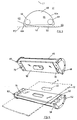
- Figure 5 is a detail view in perspective of a portion of the rotary apparatus according to the invention about to contact the workpiece;
- Figure 6 is an exploded perspective view showing the apparatus performing a punching operation;
- Figure 7 is a view similar to that of Figure 2, but illustrating a second embodiment;
- Figure 8 is a diagrammatic view showing the upper die unit only, and illustrating successive positions of one (only) die block, in the Fig 7 embodiment;
- Figure 9 is an exploded view of a detail of the embodiment of Figure 7;
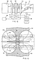
- Figure 10 is a sectional side elevation of a further embodiment;
- Figure 11 is a section along the line 11-11 of Figure 10;
- Figure 12 is a schematic top plan view of an alternate embodiment of the rotary apparatus, for intermittent operation; and
- Figure 13 is a section along the line 13-13 of Figure 12.
-
- Referring to Figure 1, there is illustrated a
roll 10 ofstrip sheet material 12 upon which it is desired to perform various forming operations.Material 12 may often be sheet metal. Such operations may typically be performed in amanufacturing line 14.Material 12 is unwound fromroll 10 and passed continuously alongline 14, in the direction indicated by arrow A. The various forming operations are performed onmaterial 12 as it passes different points alongline 14. Asmaterial 12 is unwound fromroll 10, typical first operations may be die forming operations, performed by arotary apparatus 20 according to the invention.Apparatus 20 may punch holes, or formcomplex indentations 22, or both, inmaterial 12 as it passes throughapparatus 20. Nip rollers 21, both above and belowmaterial 12,guide material 12 throughrotary apparatus 20. Subsequent operations may typically include roll-forming operations atstation 23. Further operations as desired may be carrid out atstation 24. The final operation is typically the cutting ofmaterial 12 in cuttingstation 26 intostandard lengths 28 convenient for further manufacturing or assembly processes and for storage. - Further nip rollers (not shown) may be used to guide
material 12 throughstations stations - The above description of a typical manufacturing line is provided herein in order to facilitate the description of the invention. The description of the manufacturing line is not intended to limit the invention in any way. Rather the apparatus according to the invention may be used in any manufacturing line or in any situation requiring high speed, continuous, accurate die forming of strip material.
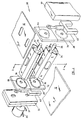
- Referring to Figure 2, there is schematically illustrated a
rotary apparatus 20 according to the invention.Motor 30 drivesupper roll unit 32 in unison with and, at the same speed, aslower roll unit 34 throughtransmission 35 andshafts 36.Material 12 passes between and is contacted by upper andlower units lower units embodiment motor 30 andtransmission 35 are such as to provide the outer surfaces of upper andlower units material 12 with essentially the same speed asmaterial 12, so that there is no slippage or relative motion between the material 12 and either or both ofupper unit 32 andlower unit 34. - However in an alternate embodiment described below, relative motion is provided for.
-
Transmission 35 andbearings 37 may be adjustable to vary the maximum distance between upper andlower units sheet material 12 of varying thicknesses or to increase the pressure applied tomaterial 12.Hydraulic pistons 40 may be attached toshafts 36 so thatupper unit 32 may be quickly removedfrom contact withmaterial 12. Such capability allows theapparatus 20 to leave linear portions ofmaterial 12 unformed, if desired. -
Motor 30,transmission 35,bearings 37 andpistons 40 may all be standard components as are well-known in the machine tooling industry. - Figure 3 illustrates in cross-section
upper die unit 32 andlower die unit 34 in position to dieform sheet material 12.Upper unit 32 rotates counter-clockwise in the direction indicated by arrowB. Lower unit 34 rotates clockwise in the direction indicated byarrow C. Material 12 moves from left to right in the direction indicated by arrow A. - It will be appreciated that the designations "upper", "lower", "left", "right", "clockwise", and counter-clockwise" are for convenience of description only and are not intended to limit the invention, which will operate equally effectively in any direction or orientation. Similarly, references to an "upper die" located in a certain position and to a corresponding "lower die" in a certain corresponding position are not intended to limit the invention. Two dies operate as a pair and the individual location of each is irrelevant to the invention so long as the pair operates together at the required location and time
-
Upper unit 32 is essentially identical tolower unit 34. Referring to Figures 3 and 4,upper unit 32 includesupper carrier member 41, which defines a longitudinal axis L1 about whichupper unit 32 rotates.Member 41 defines at least one (in the illustrated :embodiment, there are four) generally semi-circular cylindrical recesses on opening 42, defining central axes (Figure 5) extending longitudinally parallel to the axis L1 ofmember 41.Member 41 further definesabutments 43 betweenopenings 42. The outer surface ofabutments 43 define a notional circular cylindrical surface 44 (shown in cross-section as phantom circle 44). The axes L2 ofcylindrical openings 42 may lie onnotional surface 44 parallel to axis L1. However in an alternate embodiment described below this is modified. - Referring to Figures 5 and 6, upper die support blocks 46 are retained within
openings 42 by the semi-circular retaining flanges 47. Eachblock 46 is semi-cylindrical in shape having a cross-section that is segment-shaped namely, that shape bounded between the perimeter of a circle and a chord of the circle. Thus block 46 defines two surface portions: asemi-cylindrical portion 46a and aplanar portion 46b.Semi-cylindrical portion 46a is fitted within opening 42, so thatblock 46 is freely rotatable within its associatedopening 42. A first guide pin means 48 extends from one end ofblocks 46 and a second guide pin means 49 extends from the outer end guide blocks 46, and ensure that the planar portions 4gb are located in the desired position as described below. On ablock 46 pin means 48 and 49 define and lie on different axes for reasons described below. - Upper dies 50 are mounted on
planar portions 46b ofblocks 46 in any conventional manner. The die surface of a die 50 defines a forming plane P2 (Figure 5).Die 50 is mounted onblock 46 so that the plane P2 is essentially parallel to theplanar portion 46b ofblock 46 and so that the plane P2 includes the axis of opening 42, in this embodiment
Lower unit 34 compriseslower carrier member 52, defining semicylindrical openings 54,abutments 55 andsemi-cylindrical surface 56, lower support blocks 58, and flat lower dies 60. Guide pin means 62 and 63 are provided in a fashion offset at opposite ends of the block similar to the equivalent components ofupper unit 32. Retaining flanges 47 are also provided. - Each of
pins Pins 48 are guided by cam means such as acam groove 64 defined in fixedend plate 38, at one end.Pins 49 are guided by cam means such as acam groove 65 in fixedend plate 39, at the opposite end. - Similarly, on
lower unit 34, guide pins 62 and 63 are guided by corresponding cam means; e.g.,cam grooves fixed end plates -
Fixed end plate 38 is divided betweengrooves end plate 39 is split betweengrooves 66 and 72 into upper and lower end plates, 39a and 39b. Both end plates 38a and 39a are fixed by suitable means (not shown) relative to the axis L1 ofupper unit 32. Such suitable means may, for example, comprise a guide track, preventing the rotation of plates 38a and 39a relative to axis L1, and a bearing means forshaft 36 in plates 38a and 39a. - Similarly, end plates 38b and 39b are fixed relative to the axis L1 of
lower unit 34. - The provision of split end plates 38a, 38b, 39a and 39b, fixed as described above, allows the distance between
upper unit 32 andlower unit 34 to be varied as desired without interfering with the operation ofdie forming apparatus 20. Ashydraulic cylinders 40 are operated, such distance betweenunits upper unit 32, yetcam grooves pins -
Cam grooves blocks 46 whereby the forming planes P2 of dies 50 are essentially parallel tomaterial 12 immediately prior to, during and subsequent to closing. Similarly,cam grooves blocks 58 whereby the forming planes P2 of dies 60 are essentially parallel tomaterial 12 immediately prior to, during and subsequent to closing, - Because a
block 46 and ablock 58 may each be supported by two pins on different axes the blocks are less prone to rock or otherwise move within their fittings than are those found in standard rotary forming devices. Thus, in comparison to previously used rotary devices, the clearances requird by the cam follower mechanism do not have as great an effect on the accuracy of the forming operation. In fact, the double cam construction of the invention results in substantially improved forming accuracy, and thus, longer useful die life. - To further ensure accuracy,
upper support block 46 may be provided with locatingdowels 78 on either side of die 50 (see Figure 6).Lower support block 58 may be provided with corresponding dowel receiving bores 79 on either side ofdie 60. Dowels 78 and bores 79 are shaped, sized and located on either side ofstrip material 12 so that they may cooperate and register with each other without interference withmaterial 12. As upper andlower units bores 79 prior to contact withmaterial 12. As adie 50 and a die 60 come into contact withmaterial 12, thedowels 78 are fully inserted into thebore 79, thus ensuring that die 50 and die 60contact material 12 in proper registration with each other. Although accuracy is ensured by the use ofdowels 78 and bores 79,such dowels 78 and bores 79 may not always be necessary for the accurate functioning of the device according to the invention. The device as described above has been found to operate with satisfactory accuracy without such dowels and bores. - Referring to Figure 3, in operation, upper and
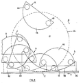
lower units upper unit 32. Such positions have been labelled in Figure 3 as positions S, U, W, and Y. The closed position ofapparatus 20, which is the position at whichmaterial 12 is formed, is defined as position S. Position S is treated as defining the starting point of the rotary cycle. Rotation continues, counter-clockwise as indicated by direction arrow B, through each of the other positions U, W and Y and returns to starting position S. Similarly, each die 60 rotates through the illustrated positions oflower unit 34. The movement of any die 60 is the mirror image of the movement of its correspondingdie 50. It will, of course, be appreciated that all dies rotate simultaneously and, at any particular time, are at different positions in the rotary cycle. - At
position S material 12 is formed bydie 50 and die 60. As rotation continues to position U, die 50 and die 60 are separated frommaterial 12. Becausepins respective cam grooves material 12.Abutments material 12. Thus, if there has been any adhesion betweenmaterial 12 and either die 50 or die 60,material 12 will be pushed away from such dies 50 or 60 and will continue to pass smoothly throughrotary apparatus 20. - As rotation continues, the cam followers cause
block 46 to rotate through the positions U, W and Y. Following position Y, dies 50 and 60 are brought into essentially parallel position for the forming operation at position S. - In an alternate embodiment, cam grooves defined in the
fixed end plates pins ramp 80 is affixed to fixed end plate 38a andramp 82 to fixed end plate 39a. Similarly associated withlower unit 34, ramps 84 and 86 are also affixed to fixed end plates 38b and 39b, respectively.Ramps curved surfaces -
Surfaces material 12 and to each other immediately prior to, during and subsequent to closing. During other parts of the rotary cycle, the precise positioning ofblocks members blocks - Consequently, when the cam followers are not in contact with
ramps Block 46 defines acircumferential channel 96.Member 41 has apost 98, adapted to fit withinchannel 96 so thatblock 46 may still orbit withinopening 42.Spring 100 is fitted withinchannel 96 and attached at one end to a wall of channel 96 (or to a post inserted in channel 96) and at the other end to post 98. In such a configuration,spring 100 tends to holdblock 46 in the position indicated as J or K in Figure 8 relative tomember 41. In this position, pin 48 is extended radially away from axis L1 whereby it may come into contact with itsrespective ramp 80 at a predetermined position in the rotary cycle. - The operation of this embodiment is best understood by referring to Figures 7 and 8. Figure 7 illustrates upper and
lower units block 46 inmember 41 shown at various positions in the rotary cycle. Successive positions are indicated by the labels J, K, H, M, N and O. Oneramp 80 and its associatedpin 48 are drawn in sold line. Theother ramp 82 and its associatedpin 49 are shown in phantom. - While only one
block 46 is illustrated, it will be appreciated thatother blocks 46 attached tomember 41 will travel through corresponding positions of the rotary cycle at different times. It will be further appreciated that while onlyupper unit 32 is illustrated, similar action is occurring inlower unit 34. - Commencing arbitrarily with position J in the rotary cycle,
spring 100 holdsblock 46 so thatpin 48 is extended away from the axis L1 ofmember 41. As rotation occurs block 46 passes through position K to position H. There is no relative motion betweenblock 46 andmember 41 from position J to position H. At position H, the forming plane P2 (Figure 5) ofdie 50 is essentially parallel tomaterial 12. - At
position H pin 48 contacts thesurface 88 oframp 80. Also, pin 49 contacts thesurface 90 oframp 82. As rotation continuesblock 46 now commences to orbit withinopening 44.Spring 100 commences to stretch.Pin 48 moves alongsurface 88.Pin 49 moves alongsurface 90. Such motion continues to position M. The surfaces 88 and 90 are shaped to ensure that plane P2 remains parallel tomaterial 12. - On lower unit 34 (not shown in Figure 8) a corresponding plane P2 of
die 60 is also essentially parallel tomaterial 12 and thus to the plane P2 ofdie 50. - As rotation continues to position M, relative rotation between
block 46 andmember 41 continues andspring 100 stretches further. At about position M planeP2 contacts material 12 and, in cooperation withdie 60, thematerial 12 is deformed as requird. - After dies 50 and 60 have thus closed, rotation continues.
Pins respective ramps material 12. Relative rotation betweenblock 46 andmember 41 continues andspring 100 stretches further. - At about position N, pin 49 which in this case is the leading pin, is removed from
ramp 82. - At about position O, pin 48 which in this case is the trailing pin, reaches the end of
ramp 80.Spring 100, which has been urgingblock 46 to rotate clockwises, may now act to returnblock 46 to its initial position with respect tomember 41, for example, as shown at position J. - Suitable limit means (not shown) allow
spring 100 to holdblock 46 within opening 42 during rotation from position J to position L. For example, the presence of an abutment means (not shown) extending into opening 42 frommember 41 would allowspring 100 to holdblock 46 securely against the abutment.Block 46 would thus be prevented from moving in itsopening 42 under the influence of centrifugal force asunit 32 rotates. - Because, in this embodiment, block 46 is pressed into place against the ramps by the rotation of
member 41 prior to closing, a solid and accurate punch is possible.Spring 100 operates to keeppins respective ramps - In other embodiments, it may be possible to use a ramp or cam groove on only one side of a die unit in conjunction with such a spring urging a die support block into contact with such ramp or groove. It may also be possible to use a ramp on one side of a die unit and a cam groove on the other side of the same unit. Use of a biasing spring may be avoided in such an embodiment.
- It will be appreciated that a die apparatus according to the invention may be used in any situation requiring the use of high speed, accurate cutting or forming. Apart from the standard hole punching or indentation forming operation described above, the apparatus of the invention may, for instance, be used with a shearing die to cut roll formed strip material with a complex, shaped edge.
- Several die units may be placed in line for forming complicated holes or shapes. For instance, a first rotary apparatus may punch a hole. A second rotary apparatus may form shapes around the hole. A third rotary apparatus may perform further operations and so on as required. Such operation would be very similar to the operation of existing progressive die presses.
- The apparatus of the invention may be used to leave unformed areas at spaced intervals along the strip material. The upper and
lower units material 12 over such intervals. - In accordance with a further embodiment of the invention as shown in Figures 10 and 11, provisions may be made for still further stabilizing the die support blocks 46 and 58, so that they are forced to adopt precisely parallel planes prior to the engagement of the two dies on the blocks.
- It will of course be appreciated that if the two die support blocks are not precisely parallel, and parallel with the workpiece, prior to the engagement of the dies on the workpiece, the workpiece will not be formed precisely, and conceivably damage may result to the dies themselves.
- In the embodiment shown in Figures 1 to 6, the
pins 78 andopenings 79 will normally provide a sufficient degree of guidance to ensure that the two blocks are precisely parallel to one another before the dies close. - However, since some degree of wear is inevitable, it is considered desirable to make provision for a still greater degree of guidance.
- Accordingly, as shown in Figures 10 and 11, the
upper die block 46 is shown with thedie guidance pin 78 received in abore 102, and being retained therein by any suitable means (not shown). - A die
block guide channel 104 is machined in either end of theblock 46, so as to replace the function of the retaining flanges 47, and is engaged by suitable retaining means (not shown) oncarrier member 41. - This feature would also be used in the
blocks 58 incarrier member 52 in this embodiment. - In order to further assist in guiding and controlling the
blocks upper die block 46, parallel to thebore 102. -
Bore 108 communicates with alongitudinal channel 110 of generally rectangular shape, extending from side to side of theblock 46 transverse to its longitudinal axis. - Each of the die blocks 46 and 58 may be provided with two such guidance bores 108, one at each end, and two
such channels 110. - An elongated
rectangular contact bar 112 is received inchannel 110, and is mounted on acylindrical guide shaft 114 extending intoguide bore 108. A counter-bore 116 is formed inshaft 114, and receives aspring 118 therein. Thespring 118 will preferably be a heavy duty compression spring. - Any suitable retaining means (not shown) will be provided for retaining the
shaft 114 in thebore 108. - The four
bars 112 on the upper and lower diemembers - The heavy duty springs 118 will yield and allow the
bars 112 to move inwardly into thechannels 110, but will, at the same time, force the faces of thebars 112 firmly into contact with one another along their length. - This function will thus ensure that the
blocks - It will be appreciated that in the form illustrated both the upper and lower die blocks 46 and 58 are provided with the same guidance bars 112 and
shafts 116. - The purpose of this is to reduce the distance of travel of each of the guide bars 112, and yet ensure that they meet and contact one another at a point early enough in the closing of the dies, that they can achieve a secure and accurate guidance function before the die is closed.
- It will, of course, be appreciated however that where dies of a different nature are in use, such that a lesser degree of travel would be acceptable, it may be permissible to provide such guidance bars 112 on only the upper or the lower of the two die blocks. If only one pair of such guidance bars 112 were used then, of course, the guidance bars would simply contact the face of the other block and provide the same guidance function as described above.
- It will be appreciated, therefor, that while this embodiment of the invention is illustrated as provided on both upper and lower die blocks and at each end, some degree of guidance function and security will be achieved by providing only one pair of such guidance bars. Conceivably also some limited degree of guidance can be achieved merely by the provision of one of such guidance bars at one end of one block.
- The invention is not, therefore, limited to any specific number of such guidance bars.
- In accordance with a further embodiment of the invention as illustrated in Figures 12 and 13, provision may be made for intermittent operation of the rotary apparatus.
- Intermittent operation may be desirable where it is intended to produce from the strip sheet material, an end product which is cut to a predetermined length. Thus, for example, if it is desired to produce sheet metal strip having a series of formations, along predetermined lengths of the strip, and intermittent discontinuities in the formations, then, as has been described above, one solution would be to simply move one of the roll units away from the other.
- Another solution to the problem is, however, to simply stop the upper and lower units momentarily and allow the strip sheet material to pass between them, without being formed or punched, for a predetermined length.
- As shown schematically in Figure 12, a typical strip sheet material line for functioning in this way would comprise a rotary cutting or forming
apparatus 120, upstream and downstream pinch rolls 122 and 124, and anuncoiler 126. The strip sheet material is indicated as 12, and in this embodiment is shown simply as being formed with generally triangular perforations oropenings 12a. A discontinuity indicated generally as 12b is indicated between two of theperforations 12a. - In this embodiment the
rotary apparatus 120 is driven by means of amotor 128, driving through a clutch 130.Clutch 130 drives therotary apparatus 120, and the drive is controlled by means of abrake 132. - A
line speed indicator 134 may be used if desired, for contacting thestrip sheet material 12. However this information can equally well be obtained in other ways, and it is illustrated here merely for the sake of clarity. - A central
data processing unit 136 provided with typical controls and displays is connected to theline speed indicator 134, and to the clutch 130 and to thebrake 132. - It may also be connected to all of the rolls, and to the
motor 128 if desired for capturing further information. - Referring now to Figure 13, the
rotary apparatus 120 is essentially similar to that described in the preceding description. Accordingly the various features are described in only general terms herein, where they are the same. Thus therotary apparatus 120 comprisescarrier members 138 and 140 havingdie support blocks - The central axis of the die blocks 142 and 144 move around a circular path, indicated in phantom as 146.
- However, the
surface portions carrier members 138 and 140 lie on the perimeter of a circle of a somewhat smaller radius than thecircle 146. - In this way, when the two
carrier members 138 and 140 are in the position illustrated in Figure 13, thesurfaces workpiece 12. - The workpiece is held in any event between the pinch rolls 122 and 124, and is therefore at all times controlled.
- By suitably programming the
processor 136 to operate the clutch 130 andbrake 132 in the correct time sequence, it is possible to stop the upper andlower carrier members 138 and 140 in the position shown in Figure 13, for a predetermined dwell time, sufficient to allow an unformed portion 12b of theworkpiece 12 to pass between them. - The
processor 136 will then again signal thebrake 132 to release and the clutch 130 to re-engage, and rotation of thecarrier members 138 and 140 will be resumed.
Claims (5)
- A die support apparatus for use in assoication with a rotary apparatus for forming or cutting material, said rotary apparatus having at lest one rotatable carrier member 32, 34, the improvement comprising:
at least one die support member, 46, 58 adapted to be supported by said carrier member, and in turn adapted to support a die for forming or cutting said material said die support member being swingable relative to said carrier member;
leading die support guide means 48, 62 mounted along a leading portion of said die support member;
trailing die support guide means 49, 63, mounted along a trailing portion of said die support member;
leading control means 64, 70 for engaging said leading guide means, and,
trailing control means 66, 72 for engaging said trailing guide means. - A die support apparatus as claimed in Claim 1 wherein said leading guide means 48, 62 is located at one end of said die support member 46, 58 and wherein said trailing guide means 49, 63 is located at the other end of said die support member.
- A die support apparatus as claimed in Claim 1 wherein said leading and trailing guide means define axes parallel to one another and spaced apart from one another.
- A die support apparatus as claimed in Claim 1 including means 100 biasing the orientation of said die support member into a predetermined orientation relative to said carrier member.
- A die support apparatus as claimed in Claim 1 including contact bar means 112, at each end of one of said die supports and slidable support means 114 for said contact bar means, whereby said contact bar means is reciprocable to and fro relative to said one die support member.
Applications Claiming Priority (5)
| Application Number | Priority Date | Filing Date | Title |
|---|---|---|---|
| US81144285A | 1985-12-20 | 1985-12-20 | |
| US06/938,406 US4732028A (en) | 1985-12-20 | 1986-12-05 | Rotary apparatus |
| EP19880302371 EP0332774B1 (en) | 1985-12-20 | 1988-03-18 | Rotary cutting and forming apparatus |
| HK98103890A HK1004745A1 (en) | 1985-12-20 | 1998-05-06 | Rotary cutting and forming apparatus |
| HK98104527A HK1005484A1 (en) | 1985-12-20 | 1998-05-26 | Die support arrangement in a rotary forming apparatus |
Related Parent Applications (1)
| Application Number | Title | Priority Date | Filing Date |
|---|---|---|---|
| EP88302371.5 Division | 1988-03-18 |
Publications (3)
| Publication Number | Publication Date |
|---|---|
| EP0530845A2 true EP0530845A2 (en) | 1993-03-10 |
| EP0530845A3 EP0530845A3 (en) | 1993-08-11 |
| EP0530845B1 EP0530845B1 (en) | 1997-12-29 |
Family
ID=27451948
Family Applications (2)
| Application Number | Title | Priority Date | Filing Date |
|---|---|---|---|
| EP19920115657 Expired - Lifetime EP0530845B1 (en) | 1985-12-20 | 1988-03-18 | Die support arrangement in a rotary forming apparatus |
| EP19880302371 Expired - Lifetime EP0332774B1 (en) | 1985-12-20 | 1988-03-18 | Rotary cutting and forming apparatus |
Family Applications After (1)
| Application Number | Title | Priority Date | Filing Date |
|---|---|---|---|
| EP19880302371 Expired - Lifetime EP0332774B1 (en) | 1985-12-20 | 1988-03-18 | Rotary cutting and forming apparatus |
Country Status (7)
| Country | Link |
|---|---|
| US (1) | US4732028A (en) |
| EP (2) | EP0530845B1 (en) |
| AT (1) | ATE161446T1 (en) |
| AU (1) | AU592491B1 (en) |
| DE (1) | DE3856093T2 (en) |
| ES (1) | ES2112876T3 (en) |
| HK (2) | HK1004745A1 (en) |
Families Citing this family (12)
| Publication number | Priority date | Publication date | Assignee | Title |
|---|---|---|---|---|
| DE4128970A1 (en) * | 1990-09-04 | 1992-03-05 | Ishikawajima Harima Heavy Ind | SHEARING DEVICE |
| US5592848A (en) * | 1991-06-03 | 1997-01-14 | Bodnar; Ernest R. | Method of simultaneously forming a pair of sheet metal structural members |
| US5669197A (en) * | 1991-06-03 | 1997-09-23 | Bodnar; Ernest Robert | Sheet metal structural member |
| US5983693A (en) * | 1995-03-15 | 1999-11-16 | Rotary Press Systems Inc. | Rotary press with cut off apparatus |
| CA2173776A1 (en) * | 1996-04-10 | 1997-10-11 | Michael Surina | Rotary forming apparatus and method of rotary forming |
| US6354180B1 (en) | 1998-12-04 | 2002-03-12 | Hill Engineering, Inc. | System for cutting sheet material |
| US8683898B2 (en) * | 2000-01-19 | 2014-04-01 | Sms Siemag Aktiengesellschaft | Method of operating a high-speed shear |
| US7228720B2 (en) * | 2002-07-03 | 2007-06-12 | Bodnar Ernest R | Rotary apparatus and method |
| US20050202948A1 (en) * | 2004-03-10 | 2005-09-15 | Jensen L. G. | Web forming machine |
| CA2479420C (en) * | 2004-08-30 | 2011-07-19 | Gcg Holdings Ltd | Rotary apparatus with multiple guides and method of forming |
| MY146311A (en) * | 2006-01-17 | 2012-07-31 | Gcg Holdings Ltd | Stud with lenghtwise indented ribs and method |
| US9376816B2 (en) | 2010-06-07 | 2016-06-28 | Scott J. Anderson | Jointed metal member |
Citations (6)
| Publication number | Priority date | Publication date | Assignee | Title |
|---|---|---|---|---|
| US1581236A (en) * | 1922-02-20 | 1926-04-20 | Central Trust Company | Apparatus for making roofing units |
| US1931468A (en) * | 1929-11-11 | 1933-10-17 | Moore Shank Company | Punching machine |
| US3066542A (en) * | 1955-04-12 | 1962-12-04 | Nat Gypsum Co | Continuous web perforating machine |
| US3239912A (en) * | 1962-01-15 | 1966-03-15 | Bennett American Corp | Continuous forging method |
| US3673834A (en) * | 1970-10-19 | 1972-07-04 | Reynolds Metals Co | Apparatus for and method of operating on container constructions |
| US3850780A (en) * | 1971-08-23 | 1974-11-26 | Fmc Corp | Extended dwell heat sealer |
Family Cites Families (8)
| Publication number | Priority date | Publication date | Assignee | Title |
|---|---|---|---|---|
| DE1060235B (en) * | 1957-04-16 | 1959-06-25 | Martin Rawe Maschf | Cutting device with rotating knives for paper processing machines, preferably tube drawing machines |
| FR2048277A5 (en) * | 1969-12-16 | 1971-03-19 | Granger Maurice | Appts for cutting a variety of shapes from - metallic sheet material |
| FR2181450A1 (en) * | 1972-04-25 | 1973-12-07 | Wilkins John | |
| DD120601A1 (en) * | 1975-07-03 | 1976-06-20 | ||
| IT1134961B (en) * | 1981-01-07 | 1986-08-20 | Tommaso Pavone | PUNCHING-RODING MACHINE WITH HORIZONTAL AND PARALLEL AXES MOLD-HOLDER TURRETS |
| SU1159692A1 (en) * | 1983-04-08 | 1985-06-07 | Предприятие П/Я М-5836 | Apparatus for punching holes in sheet material |
| JPS61146435A (en) * | 1984-12-21 | 1986-07-04 | Toyoda Gosei Co Ltd | Automatic clip setting device |
| SE458102B (en) * | 1986-03-04 | 1989-02-27 | Sven Algot Groendahl | CLAMMING MACHINE DEVICE |
-
1986
- 1986-12-05 US US06/938,406 patent/US4732028A/en not_active Ceased
-
1988
- 1988-03-18 ES ES92115657T patent/ES2112876T3/en not_active Expired - Lifetime
- 1988-03-18 DE DE19883856093 patent/DE3856093T2/en not_active Expired - Fee Related
- 1988-03-18 AT AT92115657T patent/ATE161446T1/en not_active IP Right Cessation
- 1988-03-18 EP EP19920115657 patent/EP0530845B1/en not_active Expired - Lifetime
- 1988-03-18 AU AU13304/88A patent/AU592491B1/en not_active Ceased
- 1988-03-18 EP EP19880302371 patent/EP0332774B1/en not_active Expired - Lifetime
-
1998
- 1998-05-06 HK HK98103890A patent/HK1004745A1/en not_active IP Right Cessation
- 1998-05-26 HK HK98104527A patent/HK1005484A1/en not_active IP Right Cessation
Patent Citations (6)
| Publication number | Priority date | Publication date | Assignee | Title |
|---|---|---|---|---|
| US1581236A (en) * | 1922-02-20 | 1926-04-20 | Central Trust Company | Apparatus for making roofing units |
| US1931468A (en) * | 1929-11-11 | 1933-10-17 | Moore Shank Company | Punching machine |
| US3066542A (en) * | 1955-04-12 | 1962-12-04 | Nat Gypsum Co | Continuous web perforating machine |
| US3239912A (en) * | 1962-01-15 | 1966-03-15 | Bennett American Corp | Continuous forging method |
| US3673834A (en) * | 1970-10-19 | 1972-07-04 | Reynolds Metals Co | Apparatus for and method of operating on container constructions |
| US3850780A (en) * | 1971-08-23 | 1974-11-26 | Fmc Corp | Extended dwell heat sealer |
Also Published As
| Publication number | Publication date |
|---|---|
| EP0332774A3 (en) | 1990-07-25 |
| ATE161446T1 (en) | 1998-01-15 |
| EP0332774B1 (en) | 1993-05-12 |
| ES2112876T3 (en) | 1998-04-16 |
| US4732028A (en) | 1988-03-22 |
| EP0530845A3 (en) | 1993-08-11 |
| EP0332774A2 (en) | 1989-09-20 |
| DE3856093D1 (en) | 1998-02-05 |
| HK1004745A1 (en) | 1998-12-04 |
| EP0530845B1 (en) | 1997-12-29 |
| HK1005484A1 (en) | 1999-01-08 |
| AU592491B1 (en) | 1990-01-11 |
| DE3856093T2 (en) | 1998-07-02 |
Similar Documents
| Publication | Publication Date | Title |
|---|---|---|
| US5040397A (en) | Rotary apparatus and method | |
| EP0530845B1 (en) | Die support arrangement in a rotary forming apparatus | |
| US4497196A (en) | Apparatus for performing operations on strip material | |
| US5791185A (en) | Rotary apparatus with moveable die | |
| JP3612517B2 (en) | Rotary punching device | |
| EP1554109A2 (en) | Device for punching, stamping and/or shaping flat elements | |
| US5983693A (en) | Rotary press with cut off apparatus | |
| US7335152B2 (en) | Web forming machine | |
| EP0519525B1 (en) | Method of rotary forming | |
| US4351175A (en) | Method of manufacturing an arc-like formed product and equipment for carrying out the method | |
| EP0637275B1 (en) | Rotary forming apparatus and method | |
| USRE33613E (en) | Rotary apparatus | |
| US3788177A (en) | Forming tool and fixture therefor | |
| US4019432A (en) | Rivet making machine | |
| JP2000309458A (en) | Injector rotation processing device with constant- diameter base and method for handling slender web advancing at uniform speed | |
| JPH07108419B2 (en) | Rotating device | |
| US3528318A (en) | Feed control means | |
| US3793972A (en) | Method and apparatus for feeding a sheet metal web | |
| CA1291416C (en) | Rotary apparatus | |
| US5025650A (en) | Apparatus for forming plates of irregular cross-sectional shape | |
| EA000509B1 (en) | Rotary forming apparatus and method of rotary forming | |
| EP0114799B1 (en) | Apparatus for producing stamped sections in continuously advanced strip blank | |
| AU708403B2 (en) | Rotary press with cut off apparatus | |
| JPS57187130A (en) | Forcible feeding device in punching process | |
| SU1199364A1 (en) | Arrangement for successive stamping |
Legal Events
| Date | Code | Title | Description |
|---|---|---|---|
| PUAI | Public reference made under article 153(3) epc to a published international application that has entered the european phase |
Free format text: ORIGINAL CODE: 0009012 |
|
| 17P | Request for examination filed |
Effective date: 19920912 |
|
| AC | Divisional application: reference to earlier application |
Ref document number: 332774 Country of ref document: EP |
|
| AK | Designated contracting states |
Kind code of ref document: A2 Designated state(s): AT BE CH DE ES FR GB IT LI NL SE |
|
| PUAL | Search report despatched |
Free format text: ORIGINAL CODE: 0009013 |
|
| AK | Designated contracting states |
Kind code of ref document: A3 Designated state(s): AT BE CH DE ES FR GB IT LI NL SE |
|
| 17Q | First examination report despatched |
Effective date: 19940905 |
|
| APCB | Communication from the board of appeal sent |
Free format text: ORIGINAL CODE: EPIDOS OBAPE |
|
| APCB | Communication from the board of appeal sent |
Free format text: ORIGINAL CODE: EPIDOS OBAPE |
|
| APCB | Communication from the board of appeal sent |
Free format text: ORIGINAL CODE: EPIDOS OBAPE |
|
| APCB | Communication from the board of appeal sent |
Free format text: ORIGINAL CODE: EPIDOS OBAPE |
|
| APAB | Appeal dossier modified |
Free format text: ORIGINAL CODE: EPIDOS NOAPE |
|
| GRAG | Despatch of communication of intention to grant |
Free format text: ORIGINAL CODE: EPIDOS AGRA |
|
| GRAH | Despatch of communication of intention to grant a patent |
Free format text: ORIGINAL CODE: EPIDOS IGRA |
|
| GRAH | Despatch of communication of intention to grant a patent |
Free format text: ORIGINAL CODE: EPIDOS IGRA |
|
| GRAA | (expected) grant |
Free format text: ORIGINAL CODE: 0009210 |
|
| AC | Divisional application: reference to earlier application |
Ref document number: 332774 Country of ref document: EP |
|
| AK | Designated contracting states |
Kind code of ref document: B1 Designated state(s): AT BE CH DE ES FR GB IT LI NL SE |
|
| REF | Corresponds to: |
Ref document number: 161446 Country of ref document: AT Date of ref document: 19980115 Kind code of ref document: T |
|
| REG | Reference to a national code |
Ref country code: CH Ref legal event code: EP |
|
| REF | Corresponds to: |
Ref document number: 3856093 Country of ref document: DE Date of ref document: 19980205 |
|
| ITF | It: translation for a ep patent filed |
Owner name: ING. A. GIAMBROCONO & C. S.R.L. |
|
| REG | Reference to a national code |
Ref country code: CH Ref legal event code: NV Representative=s name: TROESCH SCHEIDEGGER WERNER AG |
|
| ET | Fr: translation filed | ||
| REG | Reference to a national code |
Ref country code: ES Ref legal event code: FG2A Ref document number: 2112876 Country of ref document: ES Kind code of ref document: T3 |
|
| PLBE | No opposition filed within time limit |
Free format text: ORIGINAL CODE: 0009261 |
|
| STAA | Information on the status of an ep patent application or granted ep patent |
Free format text: STATUS: NO OPPOSITION FILED WITHIN TIME LIMIT |
|
| 26N | No opposition filed | ||
| PGFP | Annual fee paid to national office [announced via postgrant information from national office to epo] |
Ref country code: FR Payment date: 20000828 Year of fee payment: 13 |
|
| PGFP | Annual fee paid to national office [announced via postgrant information from national office to epo] |
Ref country code: AT Payment date: 20000829 Year of fee payment: 13 |
|
| PGFP | Annual fee paid to national office [announced via postgrant information from national office to epo] |
Ref country code: NL Payment date: 20000831 Year of fee payment: 13 |
|
| PGFP | Annual fee paid to national office [announced via postgrant information from national office to epo] |
Ref country code: BE Payment date: 20000918 Year of fee payment: 13 |
|
| PG25 | Lapsed in a contracting state [announced via postgrant information from national office to epo] |
Ref country code: AT Free format text: LAPSE BECAUSE OF NON-PAYMENT OF DUE FEES Effective date: 20010318 |
|
| PG25 | Lapsed in a contracting state [announced via postgrant information from national office to epo] |
Ref country code: SE Free format text: LAPSE BECAUSE OF NON-PAYMENT OF DUE FEES Effective date: 20010319 |
|
| PG25 | Lapsed in a contracting state [announced via postgrant information from national office to epo] |
Ref country code: BE Free format text: LAPSE BECAUSE OF NON-PAYMENT OF DUE FEES Effective date: 20010331 |
|
| BERE | Be: lapsed |
Owner name: BODNAR ERNEST R. Effective date: 20010331 |
|
| PG25 | Lapsed in a contracting state [announced via postgrant information from national office to epo] |
Ref country code: NL Free format text: LAPSE BECAUSE OF NON-PAYMENT OF DUE FEES Effective date: 20011001 |
|
| PGFP | Annual fee paid to national office [announced via postgrant information from national office to epo] |
Ref country code: DE Payment date: 20011031 Year of fee payment: 14 |
|
| EUG | Se: european patent has lapsed |
Ref document number: 92115657.6 |
|
| GBPC | Gb: european patent ceased through non-payment of renewal fee |
Effective date: 20010318 |
|
| PGFP | Annual fee paid to national office [announced via postgrant information from national office to epo] |
Ref country code: CH Payment date: 20011107 Year of fee payment: 14 |
|
| REG | Reference to a national code |
Ref country code: CH Ref legal event code: PL |
|
| PG25 | Lapsed in a contracting state [announced via postgrant information from national office to epo] |
Ref country code: FR Free format text: LAPSE BECAUSE OF NON-PAYMENT OF DUE FEES Effective date: 20011130 |
|
| REG | Reference to a national code |
Ref country code: CH Ref legal event code: AEN Free format text: WEITERBEHANDLUNG GUTGEHEISSEN |
|
| NLV4 | Nl: lapsed or anulled due to non-payment of the annual fee |
Effective date: 20011001 |
|
| PGFP | Annual fee paid to national office [announced via postgrant information from national office to epo] |
Ref country code: ES Payment date: 20011219 Year of fee payment: 14 |
|
| PGFP | Annual fee paid to national office [announced via postgrant information from national office to epo] |
Ref country code: SE Payment date: 20011227 Year of fee payment: 14 |
|
| REG | Reference to a national code |
Ref country code: FR Ref legal event code: ST |
|
| REG | Reference to a national code |
Ref country code: GB Ref legal event code: IF02 |
|
| REG | Reference to a national code |
Ref country code: GB Ref legal event code: 728V |
|
| PGFP | Annual fee paid to national office [announced via postgrant information from national office to epo] |
Ref country code: GB Payment date: 20020219 Year of fee payment: 14 |
|
| NLXE | Nl: other communications concerning ep-patents (part 3 heading xe) |
Free format text: A REQUEST FOR RESTORATION TO THE PRIOR STATE (ART. 23 OF THE PATENTS ACT) HAS BEEN FILED ON 11.01.02. |
|
| PG25 | Lapsed in a contracting state [announced via postgrant information from national office to epo] |
Ref country code: GB Free format text: LAPSE BECAUSE OF NON-PAYMENT OF DUE FEES Effective date: 20020318 |
|
| PG25 | Lapsed in a contracting state [announced via postgrant information from national office to epo] |
Ref country code: ES Free format text: LAPSE BECAUSE OF NON-PAYMENT OF DUE FEES Effective date: 20020319 |
|
| REG | Reference to a national code |
Ref country code: GB Ref legal event code: 728Y |
|
| PG25 | Lapsed in a contracting state [announced via postgrant information from national office to epo] |
Ref country code: LI Free format text: LAPSE BECAUSE OF NON-PAYMENT OF DUE FEES Effective date: 20020331 Ref country code: CH Free format text: LAPSE BECAUSE OF NON-PAYMENT OF DUE FEES Effective date: 20020331 |
|
| REG | Reference to a national code |
Ref country code: FR Ref legal event code: FC |
|
| PG25 | Lapsed in a contracting state [announced via postgrant information from national office to epo] |
Ref country code: DE Free format text: LAPSE BECAUSE OF NON-PAYMENT OF DUE FEES Effective date: 20021001 |
|
| GBPC | Gb: european patent ceased through non-payment of renewal fee |
Effective date: 20020318 |
|
| REG | Reference to a national code |
Ref country code: CH Ref legal event code: PL |
|
| NLXE | Nl: other communications concerning ep-patents (part 3 heading xe) |
Free format text: THE REQUEST FOR RESTORATION TO THE PRIOR STATE AS PROVIDED FOR IN ARTICLE 23 OF THE PATENTS ACT 1995 (SEE PUBLICATION IN HEADING XE OF THE PATENT BULLETIN OF 20020301/03) HAS BEEN REJECTED. |
|
| REG | Reference to a national code |
Ref country code: ES Ref legal event code: FD2A Effective date: 20030410 |
|
| PG25 | Lapsed in a contracting state [announced via postgrant information from national office to epo] |
Ref country code: IT Free format text: LAPSE BECAUSE OF NON-PAYMENT OF DUE FEES Effective date: 20050318 |
|
| APAH | Appeal reference modified |
Free format text: ORIGINAL CODE: EPIDOSCREFNO |