EP0530786B1 - Airgap hood for a gap-tube motor and also method of manufacturing an airgap hood - Google Patents
Airgap hood for a gap-tube motor and also method of manufacturing an airgap hood Download PDFInfo
- Publication number
- EP0530786B1 EP0530786B1 EP92115016A EP92115016A EP0530786B1 EP 0530786 B1 EP0530786 B1 EP 0530786B1 EP 92115016 A EP92115016 A EP 92115016A EP 92115016 A EP92115016 A EP 92115016A EP 0530786 B1 EP0530786 B1 EP 0530786B1
- Authority
- EP
- European Patent Office
- Prior art keywords
- tube
- air gap
- section
- deep
- smaller diameter
- Prior art date
- Legal status (The legal status is an assumption and is not a legal conclusion. Google has not performed a legal analysis and makes no representation as to the accuracy of the status listed.)
- Expired - Lifetime
Links
Images


Classifications
-
- H—ELECTRICITY
- H02—GENERATION; CONVERSION OR DISTRIBUTION OF ELECTRIC POWER
- H02K—DYNAMO-ELECTRIC MACHINES
- H02K5/00—Casings; Enclosures; Supports
- H02K5/04—Casings or enclosures characterised by the shape, form or construction thereof
- H02K5/12—Casings or enclosures characterised by the shape, form or construction thereof specially adapted for operating in liquid or gas
- H02K5/128—Casings or enclosures characterised by the shape, form or construction thereof specially adapted for operating in liquid or gas using air-gap sleeves or air-gap discs
-
- F—MECHANICAL ENGINEERING; LIGHTING; HEATING; WEAPONS; BLASTING
- F04—POSITIVE - DISPLACEMENT MACHINES FOR LIQUIDS; PUMPS FOR LIQUIDS OR ELASTIC FLUIDS
- F04D—NON-POSITIVE-DISPLACEMENT PUMPS
- F04D13/00—Pumping installations or systems
- F04D13/02—Units comprising pumps and their driving means
- F04D13/06—Units comprising pumps and their driving means the pump being electrically driven
- F04D13/0606—Canned motor pumps
- F04D13/0626—Details of the can
-
- H—ELECTRICITY
- H02—GENERATION; CONVERSION OR DISTRIBUTION OF ELECTRIC POWER
- H02K—DYNAMO-ELECTRIC MACHINES
- H02K15/00—Methods or apparatus specially adapted for manufacturing, assembling, maintaining or repairing of dynamo-electric machines
- H02K15/14—Casings; Enclosures; Supports
Definitions
- the invention relates to a can for a canned motor, with a can, the interior of which serves as a rotor space for receiving a rotor of the canned motor, with a bottom which is arranged at a rear end of the can and which closes this end and has a pipe section which is smaller than the can diameter serves to receive a rear bearing of the rotor, with the can, bottom and its tube section being formed as a one-piece deep-drawn part, and with an annular flange being formed at one front end of the can, in one piece therewith.
- the invention further relates to a method for producing such a can for a canned motor.
- the containment shell known from it is designed as a one-piece deep-drawn part, with a cylindrical jacket tube, which surrounds the containment shell, is integrally connected to the flange, which is formed at the front open end of the containment shell, and at such a distance that between the outside of the containment shell and The stator winding of the rotor can be accommodated on the inside of the cylindrical jacket tube.
- This shape serves to ensure reliable protection against the ingress of water into the stator winding in the event of failure of the shaft sealing rings of the pump shaft.
- this structural configuration In addition to the formation of the containment shell with the area of smaller diameter provided at the rear end for receiving a rear shaft bearing, this structural configuration also requires additional further deformation paths to form the cylindrical casing tube.
- the cylindrical casing tube is formed after the can tube has been formed. Care must be taken to ensure that no deformation of the already formed can takes place during this shaping, because a high degree of dimensional accuracy is necessary in the area of the can because the can must fit exactly into the air gap between the stator and the rotor. If this form stability is not given, the canned motor cannot run smoothly.
- a containment shell is known, at the front open end of which an annular flange is formed.
- the containment shell is attached to a part of the housing of the canned motor via this annular flange, an annular flange projecting somewhat from this part into the interior of the can, so that an abutment shoulder is formed on which the containment shell is located in the area of its front end and in the area of its annular flange fits properly.
- a seal is placed between the flange of the containment shell and the housing component.
- the mechanical connection is made using a screw connection.
- this ring has an annular flange pointing in the direction of the cylinder axis of the containment shell, the axial length of which corresponds approximately to the axial length of the flange of the housing part which extends into the inside of the open end of the containment shell. Via this ring, the forces exerted by the screws can now be distributed evenly over the seal without the fear of impairing the relatively thin ring flange of the containment shell.
- the pushed-on ring has in its axially extending ring flange area such an inside diameter that exactly corresponds to the outside diameter of the canned body. This can cause scratches or grooves on the outside of the can when the ring is slid on.
- the assembly of the numerous parts is complex.
- a canned motor is understood to mean an electric motor which is used in particular to drive pumps, for example circulation pumps.
- “Canned tube” is understood to mean a tubular or socket-shaped element which, in the case of a circulating pump, creates the separation between a wet interior and a dry exterior.
- the interior of the cylindrical can is used to hold the rotor of the electric motor: the stator of the electric motor is arranged around the outside of the can.
- the name “can” comes from the fact that the tubular section extends along the air gap between the stator and the rotor. At an outer rear end of the can, there is a bottom that closes this end, which has a smaller diameter tube section than the can, in which a bearing of the shaft of the rotor is received.
- an approximately ring-shaped bearing plate is attached, which serves as a mounting flange.
- the front, open end region of the can serves to receive an insert, which is a bearing for a front end of the shaft of the Contains rotors.
- the canned motor mentioned at the outset serves to drive a circulating pump, the impeller of which sits on a section of the shaft of the rotor which projects into the pump chamber.
- the medium circulated by the impeller can enter the interior of the can and can be used there to cool the rotor.
- the assembly of the bearing plate, can and rear floor with a tubular section also serves to create a sealing seal between the wet interior and the dry exterior.
- This assembly which is composed of three parts, is to produce the cylindrical can from an initially flat sheet metal part by shaping it into a tubular body and welding it over a longitudinal seam to form a hollow cylindrical body.
- the desired thin wall thickness in the range of approximately 0.3 mm is achieved by milling this component.
- the serving as the rear end of the can open at both ends bottom with the smaller diameter tube section for receiving the bearing of the rotor is formed as a separate part, for example as a stamped part, and then connected, for example by welding to the rear end of the can.
- the front end shield serving as a fastening flange is formed as a separate part and then connected to the front open end of the can via a welding process.
- the resulting component which is composed of three separate parts, is referred to as a "containment shell".
- a disadvantage of a containment shell of the type mentioned at the outset and of its production process is that it is very complex. Particularly in large series production, as is customary for canned motors, with production sizes in the range of 2 to 3 million per year, this complex production leads to a considerable outlay in terms of apparatus and logistics.
- the manufacture of the three individual parts that make up the containment shell, in particular using various types of shaping devices, such as flexing devices, punching or pressing devices, is very complex, as is the subsequent method for joining these three parts.
- the containment shell is intended to create a sealing seal between the wet interior and the dry exterior of a pump motor
- connection points, usually welds, between the end regions of the cylindrical can and the components to be attached must be correspondingly large-scale and expensive to produce Ensure tightness. This also requires extensive sealing tests.
- the object of the present invention is therefore to create a containment shell of the type mentioned at the outset, which has a simple construction which is simple to produce.
- the object is achieved by a containment shell in that the can has a slightly widened, larger-diameter section at the front end region.
- the object is achieved by a method in that a slightly widened, larger-diameter section is formed at the end of the deep-drawing processes at the front open end region of the can.
- a can is produced over several deep-drawing processes in such a way that the flange formed at the open end has only a relatively small radial dimension, towards which, viewed in the direction of the closed end of the flange, the slightly widened, larger diameter section follows.
- the transition at the rear end of the canned tube from the area with a large diameter to the tube section with a smaller diameter is also seen in its own right as an annular flange which, for example when deep-drawing the tube section with a smaller diameter, can in turn serve as an "auxiliary flange", that is to hold the rear end of the can during the molding of the smaller-diameter tube section, which can then also serve as a starting point for an ejecting mandrel for pulling off the actual shaping mandrel.
- This "auxiliary flange" also remains an integral, one-piece component of the containment shell to be produced and does not have to be separated.
- the one-piece design of the rear closed end region of the can as a one-piece deep-drawn part facilitates manufacture compared to the above-mentioned method in particular because the deep-drawing processes can be carried out on a single device, usually in successive steps in a step press. This eliminates the need for different types of separate devices for forming these now one-piece parts.
- This connection process i.e. the welding itself, is omitted, which also has significant positive facilitating effects, for example with regard to workplace design, occupational safety and environmental compatibility.
- the ring flange formed on the opposite front end can now be used to mount the containment shell in the pump housing.
- the ring flange can then be designed in such a way that it is itself sufficiently large to directly connect to the pump housing, or it can serve as a connecting element for further mounting elements, for example a separate fastening flange.
- Overall, a considerable simplification of the outlay in terms of apparatus for producing the containment shell is created, and the logistical structure of the interacting devices is also considerably simplified, since the entire manufacturing processes can be carried out on a single step press, which is fed, for example, at one end to a flat disk-shaped blank and at the other End of the finished, molded containment can is removed.
- complex control measures at connection points for example the welding points mentioned at the outset, are no longer necessary, since there are no longer any such points.
- the provision of the slightly widened, larger-diameter section according to the present invention has the advantage that an additional mounting flange, a so-called bearing plate, can be guided over the containment shell from the rear end and can then be pressed onto the expanded, large-diameter section in a press fit.
- the end flange already present also serves as an end stop and prevents the end shield from being pushed beyond the front open end.
- the inside diameter of the end shield to be pushed over can then be dimensioned such that it is somewhat larger than the outside diameter of the can in the unexpanded area. As a result, the end shield can then be pushed over the outside of the can without causing scratches or the like on the outside thereof.
- stator can then be securely and firmly mounted on the outside of the canned tube during final assembly.
- a welding process for example laser welding, can also follow.
- an opening is provided in a base which closes a rear end of the smaller-diameter tube section at the rear end of the can.
- This measure of providing an opening which is known per se, has the advantage that access to a front rear end of the rotor shaft is possible from the outside, so that a stuck rotor can be started again.
- the pipe section of smaller diameter has a slightly narrower section of smaller diameter at a rear region.
- This measure has the advantage that an annular disc can be press-fitted from the inside into the smaller-diameter section of the pipe section.
- the outside diameter of the ring washer is dimensioned such that it is somewhat smaller than the inside diameter of the pipe section in the region which is not additionally restricted.
- the first section of the pipe section which is not further narrowed, subsequently serves as a bearing seat for a bearing accommodated on the rear end of the rotor shaft, which is usually also press-fitted into the tubular section. If there are grooves or scratches due to the assembly of the ring washer, the secure seating of the shaft bearing is no longer guaranteed.
- the disc inserted in the press fit can still be captively connected to the pipe section by means of a welding process, this being done, for example, by laser welding.
- This laser welding is preferably carried out at the same time as the welding of the annular disk-shaped bearing plate pushed over the outside of the can.
- the pressed-in and possibly welded washer preferably has an internal thread into which a threaded sealing plug can be screwed in from the rear, which is also for one provides a sealing closure for the opening provided at the rear end region of the tubular section.
- a pot-shaped blank is first deep-drawn, which is closed at a rear end by a base and is provided with an annular flange at a front end, and subsequently in a second series of deep-drawing operations, a smaller-diameter pipe section extending from the rear end of the blank is produced.
- This measure has the advantage that the hollow cylindrical body of the can is produced by means of pulling mandrels designed simply as cylinders, the desired thin wall thickness of the can being produced by the stretching processes.
- the ring flange at the open front end and the bottom at the opposite closed end still have roughly the original thickness.
- the hollow section is then formed in a second series of deep-drawing operations from the mostly still flat bottom of the already finished canned body, this then being accomplished successively with a series of mandrels of correspondingly smaller diameter.
- the corresponding step press is then constructed in such a way that there is initially a series of very large mandrels which form the canned body, followed by a series of mandrels of smaller diameter for the formation of the smaller-diameter pipe section.
- This has considerable advantages in the construction of the step press and the control of the individual deep-drawing tools. First and second series are thus carried out in direct succession in one device.
- these deep-drawing processes are coupled to one another, that is to say that preforms of the actual canned tube and preforms of the tubular section are produced simultaneously via partial shaping processes.
- a pot with an annular flange is made at the front open end.
- This measure has the advantage that an annular flange is formed during the first deep-drawing process, which enables the blank to be held or the blank to be detached from the mandrel.
- the provision of the slightly widened end region of the can in the region of the ring flange for pressing on the end shield, and the provision of the somewhat narrowed end section of the hollow section at the rear closed end is preferably accomplished at the end of the series of deep-drawing processes, so that the dimensional accuracy achieved in these shaping processes is not is affected by subsequent further deep-drawing processes.
- This measure has the advantage that very dimensionally accurate sections can be produced for connection to the end shield or the annular disk.
- the ring flange which has already been formed initially, is not exactly circular in the circumferential direction, but has a wavy line, so that, if desired, a final circumferential trimming to an exact circular shape can be provided.
- FIG. 1 An exemplary embodiment of a can 10 according to the invention shown in FIG. 1 has a cylindrical can 12, the rear end 14 of which is closed by a base 15. The bottom 15 and the can 12 are formed in one piece.
- the canned tube 12 merges at the rear end 14 via an annular flange region 16 into a tube section 18 of smaller diameter.
- a rear end 20 of the pipe section 18 is closed off by a flat bottom 22, which is in the middle has a circular opening 24.
- the flat bottom 22 runs parallel to the ring flange region 16.
- annular disc 26 is received in the press fit, which, as indicated by arrows 27, was pressed into the interior of the tube section 18 from the canned tube 12.
- the annular disk 26 has a threaded opening 28 in the center which is aligned with the opening 24.
- the can 12 is provided with an outwardly directed circumferential ring flange 32 which is formed in one piece with the can 12.
- a bearing plate 34 which is pushed over the outside of the can 12, lies on the ring flange 32, as shown by arrows 35.
- the bearing plate 34 is welded to the ring flange 32 and the ring disk 26 is welded to the rear end region of the pipe section 18, this being done in particular by laser welding.
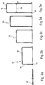
- FIGS. 2a-2e and FIGS. 3a-3e show the various preferred shapes or the corresponding blanks which are traversed starting from the plate 40 shown in FIG. 2a until the can in the final shape in FIG. 1 is reached .
- a first pot-shaped blank 41 is first shown, which has a cylindrical body 46 which is supported by a flat bottom 48 on a rear (top in the illustration of FIG. 2b) Bottom is closed.
- a circumferential ring flange 44 is provided at the opposite end.
- the blank 41 could be held during deep drawing via the ring flange 44 or pulled off as a point of application for pulling off the blank from a deep-drawing mandrel (not shown here) of a deep-drawing tool of the step press, not shown.
- the pot-shaped blank 41 is shaped in the form of the fourth blank shown in FIG. 2e, passing through the second blank or third blank shown in FIGS. 2c and 2d.
- the fourth blank 54 has a cylindrical body 57, the diameter 58 of which already corresponds to the inside diameter of the can 12 (see FIG. 1).
- the multiple stretching of the cylindrical side walls of the blanks 52, 53, 54 starting from the plate 40 results in a decrease in the material thickness in the cylindrical body 57 starting from approximately 0.4 mm material thickness in the plate 40 to 0.3 mm.
- the material thickness in the area of the bottom 56 and the flange 60 is approximately unchanged.
- a tube section with a smaller diameter than the diameter of the cylindrical body 57 is formed from the bottom 56 of the fourth blank 54 and the end region of the cylindrical body 57 surrounding it.
- a fifth blank 65 is first formed with a relatively wide and low first tube section 71, which via the second tube section 72 of the sixth blank 66 in the third tube section shown in FIG. 3c of the seventh blank 67 was formed.
- the third pipe section 73 already has the clear inner diameter and the depth of the pipe section 18 shown in FIG. 1.
- a narrowed section 76 is formed at the end region of the third pipe section, the diameter of which is approximately 0.2 mm is less than that of the non-restricted third pipe section 73.
- a widened section 78 is produced in the region of the open end of the eighth blank, the outer diameter of which is approximately 0.1 mm larger than the outer diameter of the unexpanded region of the eighth blank 68.
- the opening 24 (see also FIG. 1) is punched out in the base 80 of the third tube section 73.
- the ring flange 32 is cut into its final circular peripheral shape. Due to the anisotropy of the metallic material, the flange arranged at the open end of the respective blanks gradually takes on a wavy circumferential contour, since more or less material is drawn off from the ring flange area depending on the spatial direction.
- a canned motor 90 is shown in highly schematic form, in which the can 10 shown in FIG. 1 is installed. 4, a plug 92 is screwed into the opening 24 or into the threaded opening of the annular disc 26 at the upper end (in the terminology used here) of the canned motor 90.
- a bearing 94 is seated in the tube section 18 and sits on an end region of a shaft 96.
- an insert 98 is inserted, which carries another bearing 100 of the shaft 96.
- the part accommodated in the interior 38 of the can 12 of the can 10, that is to say bearings 94, 100, shaft 96 and corresponding windings (not described here in greater detail) forms a rotor 102 of the can motor 90.
- stator 104 of the canned motor 90 is arranged around the outside of the can 10.
- the can 10 is, as is known per se in the prior art, arranged in a gap between the rotor 102 and the stator 104 of the canned motor 90 and ensures that these spaces are sealed off from one another.
- bearing plate 34 is sealingly connected to corresponding parts of the housing of the canned motor 90, which are not described in greater detail here.
- the shaft 96 is provided with a pin 106 on which an impeller 108 is seated, which ensures the circulation of the medium which is to be moved by the pump, the drive of which by the Canned motor 90 takes place.
- the medium for cooling the rotor (102) can enter the interior of the containment shell (10).
- the shaft 96 is provided with a slot 110, via which the fixed shaft 96 can be freely rotated by means of a tool when the rotor 102 is stuck and the plug 92 is unscrewed.
Description
Die Erfindung betrifft einen Spalttopf für einen Spaltrohrmotor, mit einem Spaltrohr, dessen Innenraum als Rotorraum zur Aufnahme eines Rotors des Spaltrohrmotores dient, mit einem an einem hinteren Ende des Spaltrohres angeordneten, dieses Ende abschließenden Boden, der einen gegenüber dem Spaltrohrdurchmesser geringeren Rohrabschnitt aufweist, der zur Aufnahme eines hinteren Lagers des Rotors dient, wobei Spaltrohr, Boden und dessen Rohrabschnitt als einstückiges Tiefziehteil ausgebildet sind, und wobei an einem vorderen Ende des Spaltrohres, einstückig mit diesem, ein Ringflansch ausgeformt ist.The invention relates to a can for a canned motor, with a can, the interior of which serves as a rotor space for receiving a rotor of the canned motor, with a bottom which is arranged at a rear end of the can and which closes this end and has a pipe section which is smaller than the can diameter serves to receive a rear bearing of the rotor, with the can, bottom and its tube section being formed as a one-piece deep-drawn part, and with an annular flange being formed at one front end of the can, in one piece therewith.
Die Erfindung betrifft ferner ein Verfahren zum Herstellen eines derartiges Spalttopfes für einen Spaltrohrmotor.The invention further relates to a method for producing such a can for a canned motor.
Ein derartiger Spalttopf und ein Verfahren zu dessen Herstellung ist aus der DE-A-3 609 311 bekannt.Such a containment shell and a method for its production is known from DE-A-3 609 311.
Der daraus bekannte Spalttopf ist als einstückiges Tiefziehteil ausgebildet, wobei sich an den Flansch, der am vorderen offenen Ende des Spalttopfes ausgebildet ist, einstückig ein zylindrisches Mantelrohr anschließt, das den Spalttopf umrundet, und zwar in einem derartigen Abstand, daß zwischen Außenseite des Spalttopfs und Innenseite des zylindrischen Mantelrohres die Ständerwicklung des Rotors aufgenommen werden kann. Diese Ausformung dient dazu, einen sicheren Schutz gegen das Eindringen von Wasser in die Ständerwicklung bei Versagen von Wellendichtringen der Pumpenwelle sicherzustellen.The containment shell known from it is designed as a one-piece deep-drawn part, with a cylindrical jacket tube, which surrounds the containment shell, is integrally connected to the flange, which is formed at the front open end of the containment shell, and at such a distance that between the outside of the containment shell and The stator winding of the rotor can be accommodated on the inside of the cylindrical jacket tube. This shape serves to ensure reliable protection against the ingress of water into the stator winding in the event of failure of the shaft sealing rings of the pump shaft.
Diese konstruktive Ausgestaltung verlangt neben der Ausformung des Spalttopfes mit dem am hinteren Ende vorgesehenen durchmessergeringeren Bereich zurAufnahme eines hinteren Wellenlagers noch zusätzliche weitere Verformgänge zur Ausbildung des zylindrischen Mantelrohrs. Wenngleich in diesem Dokument das Herstellungsverfahren dieses kompliziert geformten Gebildes nicht näher beschrieben ist, erscheint es einleuchtend, daß das zylindrische Mantelrohr nach Ausbildung des Spaltrohrtopfes geformt wird. Dabei ist Sorge zu tragen, daß bei dieser Formung keine Verformung des bereits ausgebildeten Spalttopfes stattfindet, denn im Bereich des Spalttopfes ist eine hohe Maßhaltigkeit deswegen notwendig, da der Spalttopf exakt in den Luftspalt zwischen Stator und Rotor passen muß. Ist diese Formhaltigkeit nicht gegeben, ist kein störungsfreier Lauf des Spaltrohrmotores gewährleistet.In addition to the formation of the containment shell with the area of smaller diameter provided at the rear end for receiving a rear shaft bearing, this structural configuration also requires additional further deformation paths to form the cylindrical casing tube. Although the production process of this complex shaped structure is not described in more detail in this document, it seems obvious that the cylindrical casing tube is formed after the can tube has been formed. Care must be taken to ensure that no deformation of the already formed can takes place during this shaping, because a high degree of dimensional accuracy is necessary in the area of the can because the can must fit exactly into the air gap between the stator and the rotor. If this form stability is not given, the canned motor cannot run smoothly.
Aus der BE-A-626 708 ist ein Spalttopf bekannt, an dessen vorderem offenen Ende ein Ringflansch ausgeformt ist. Der Spalttopf wird über diesen Ringflansch an einem Teil des Gehäuses des Spaltrohrmotores befestigt, wobei von diesem Teil ein Ringflansch etwas in den Innenraum des Spalttopfes vorspringt, so daß eine Anlageschulter gebildet ist, an der der Spalttopf im Bereich seines vorderen Endes sowie im Bereich seines Ringflansches passend sitzt. Zwischen Flansch des Spalttopfes und dem Gehäusebauteil ist eine Dichtung gelegt. Die mechanische Verbindung erfolgt über eine Schraubverbindung. Damit der Druck der Schrauben gleichmäßig auf das Dichtungsmaterial verteilt werden kann, und da der Spalttopf im Ringflanschbereich sehr dünn ausgebildet ist, wird zuvor von hinten über den Spalttopf noch zusätzlich ein Ring aufgeschoben, dessen Ringbreite in etwa dem Flansch des Spalttopfes entspricht. Ferner weist dieser Ring einen in Richtung der Zylinderachse des Spalttopfes weisenden Ringflansch auf, dessen axiale Länge in etwa der axialen Länge des in die Innenseite des offenen Endes des Spalttopfes hineinreichenden Flansches des Gehäuseteiles entspricht. Über diesen Ring können nun die von den Schrauben ausgeübten Kräfte gleichmäßig auf die Dichtung verteilt werden, ohne daß Beeinträchtigungen am relativ dünnen Ringflansch des Spalttopfes zu befürchten sind. Der übergeschobene Ring weist in seinem axial erstreckenden Ringflanschbereich einen solchen Innendurchmesserauf, der genau dem Außendurchmesser des Spaltrohrkörpers entspricht. Dadurch können an der Außenseite des Spaltrohres Kratzer oder Rillen beim Aufschieben des Ringes entstehen. Die Montage der zahlreichen Teile ist aufwendig.From BE-A-626 708 a containment shell is known, at the front open end of which an annular flange is formed. The containment shell is attached to a part of the housing of the canned motor via this annular flange, an annular flange projecting somewhat from this part into the interior of the can, so that an abutment shoulder is formed on which the containment shell is located in the area of its front end and in the area of its annular flange fits properly. A seal is placed between the flange of the containment shell and the housing component. The mechanical connection is made using a screw connection. So that the pressure of the screws can be evenly distributed on the sealing material, and since the containment shell is very thin in the ring flange area, an additional ring is slid on from above via the containment can, the ring width of which roughly corresponds to the flange of the containment can. Furthermore, this ring has an annular flange pointing in the direction of the cylinder axis of the containment shell, the axial length of which corresponds approximately to the axial length of the flange of the housing part which extends into the inside of the open end of the containment shell. Via this ring, the forces exerted by the screws can now be distributed evenly over the seal without the fear of impairing the relatively thin ring flange of the containment shell. The pushed-on ring has in its axially extending ring flange area such an inside diameter that exactly corresponds to the outside diameter of the canned body. This can cause scratches or grooves on the outside of the can when the ring is slid on. The assembly of the numerous parts is complex.
Aus der DE-A-3 538 976 ist ein Spalttopf bekannt, an dessen hinterem, durchmessergeringerem Endabschnitt im Boden eine Öffnung vorgesehen ist, in die eine Schraube eindrehbar ist.From DE-A-3 538 976 a containment can is known, at the rear, smaller diameter end section of which there is an opening in the bottom into which a screw can be screwed.
Durch Ausdrehen der Schraube ist ein Zugang an das hintere Ende des Rotors möglich, beispielsweise um diesen bei feststehenden Rotor wieder andrehen zu können.By unscrewing the screw, access to the rear end of the rotor is possible, for example in order to be able to turn it on again when the rotor is stationary.
Unter einem Spaltrohrmotorversteht man einen Elektromotor, der insbesondere zum Antrieb von Pumpen, beispielsweise Umwälzpumpen, dient. Unter "Spaltrohr" versteht man ein rohr- bzw. buchsenförmiges Element, das bei einer Umwälzpumpe die Trennung zwischen einem nassen Innenraum und einem trockenen Außenraum herstellt. Der Innenraum des zylindrischen Spaltrohres dient zur Aufnahme des Rotors des Elektromotors: um die Außenseite des Spaltrohres herum ist der Stator der Elektromotors angeordnet. Der Name "Spaltrohr" kommt daher, daß sich der rohrförmige Abschnitt entlang des Luftspaltes zwischen Stator und Rotor erstreckt. An einem außeren hinteren Ende des Spaltrohres ist ein dieses Ende abschließender Boden vorhanden, der gegenüber dem Spaltrohr einen durchmessergeringeren Rohrabschnitt aufweist, in den ein Lager der Welle des Rotors aufgenommen ist. Am gegenüberliegenden, vorderen Ende des Spaltrohres ist ein etwa ringscheibenförmiges Lagerschild angebracht, das als Befestigungsflansch dient. Der vordere, offene Endbereich des Spaltrohres dient zur Aufnahme eines Einsatzes, der ein Lager für ein vorderes Ende der Welle des Rotors enthält. Der eingangs erwähnte Spaltrohrmotor dient zum Antrieb einer Umwälzpumpe, deren Laufrad auf einem in den Pumpenraum ragenden Abschnitt der Welle des Rotors sitzt. Das vom Laufrad umgewälzte Medium kann in den Innenraum des Spaltrohres eintreten und dort zur Kühlung des Rotors herangezogen werden. Der Zusammenbau aus Lagerschild, Spaltrohr und hinterem Boden mit rohrförmigem Abschnitt dient zugleich dazu, einen dichtenden Abschluß zwischen nassem Innenraum und trockenem Außenraum herzustellen.A canned motor is understood to mean an electric motor which is used in particular to drive pumps, for example circulation pumps. “Canned tube” is understood to mean a tubular or socket-shaped element which, in the case of a circulating pump, creates the separation between a wet interior and a dry exterior. The interior of the cylindrical can is used to hold the rotor of the electric motor: the stator of the electric motor is arranged around the outside of the can. The name "can" comes from the fact that the tubular section extends along the air gap between the stator and the rotor. At an outer rear end of the can, there is a bottom that closes this end, which has a smaller diameter tube section than the can, in which a bearing of the shaft of the rotor is received. At the opposite, front end of the can, an approximately ring-shaped bearing plate is attached, which serves as a mounting flange. The front, open end region of the can serves to receive an insert, which is a bearing for a front end of the shaft of the Contains rotors. The canned motor mentioned at the outset serves to drive a circulating pump, the impeller of which sits on a section of the shaft of the rotor which projects into the pump chamber. The medium circulated by the impeller can enter the interior of the can and can be used there to cool the rotor. The assembly of the bearing plate, can and rear floor with a tubular section also serves to create a sealing seal between the wet interior and the dry exterior.
Ein Verfahren zur Herstellung dieses aus drei Teilen aufgebauten Zusammenbaus besteht darin, das zylindrische Spaltrohr aus einem zunächst ebenen Blechteil dadurch herzustellen, daß dieses in einen rohrförmigen Körper geformt wird und über eine Längsnaht zu einem hohlzylindrischen Körper verschweißt wird. Durch Walken dieses Bauelements wird die gewünschte dünne Wandstärke im Bereich von etwa 0,3 mm erzielt. Der als hinterer Abschluß des an beiden Enden offenen Spaltrohres dienende Boden mit dem durchmessergeringeren Rohrabschnitt zur Aufnahme des Lagers des Rotors wird als separates Teil geformt, zum Beispiel als Stanzteil, und anschließend beispielsweise über eine Verschweißung mit dem hinteren Ende des Spaltrohres verbunden. Gleichermaßen wird das vordere als Befestigungsflansch dienende Lagerschild als separates Teil ausgeformt und anschließend mit dem vorderen offenen Ende des Spaltrohres über einen Verschweißvorgang verbunden. Das daraus resultierende, aus drei separaten Teilen zusammengesetzte Bauteil wird als "Spalttopf' bezeichnet.One method for producing this assembly, which is composed of three parts, is to produce the cylindrical can from an initially flat sheet metal part by shaping it into a tubular body and welding it over a longitudinal seam to form a hollow cylindrical body. The desired thin wall thickness in the range of approximately 0.3 mm is achieved by milling this component. The serving as the rear end of the can open at both ends bottom with the smaller diameter tube section for receiving the bearing of the rotor is formed as a separate part, for example as a stamped part, and then connected, for example by welding to the rear end of the can. Likewise, the front end shield serving as a fastening flange is formed as a separate part and then connected to the front open end of the can via a welding process. The resulting component, which is composed of three separate parts, is referred to as a "containment shell".
Nachteilig an einem Spalttopf der eingangs genannten Art sowie an dessen Herstellungsverfahren ist, daß dieses sehr aufwendig ist. Insbesondere in der Großserienproduktion, wie sie bei Spaltrohrmotoren üblich ist, wobei Herstellungsgrößen im Bereich von 2 bis 3 Millionen pro Jahr vorhanden sind, führt diese aufwendige Herstellung zu einem erheblichen apparativen und logistischen Aufwand. Das Herstellen der drei Einzelteile, die den Spalttopf aufbauen, insbesondere über verschiedenartige formgebende Vorrichtungen, wie Walkvorrichtungen, Stanz- oder Preßvorrichtungen, ist sehr aufwendig, ebenso das anschließende Verfahren zum Zusammenfügen dieser drei Teile. Da, wie zuvor erwähnt, der Spalttopf einen dichtenden Abschluß zwischen dem nassen Innenraum und dem trockenen Außenraum eines Pumpenmotors schaffen soll, müssen die Verbindungsstellen, meist Schweißstellen, zwischen den Endbereichen des zylindrischen Spaltrohres un den anzufügenden Bauteilen entsprechend großflächig und aufwendig hergestellt werden, um die Dichtheit sicherzustellen. Dazu sind auch aufwendige Dichtungsprüfungen notwendig.A disadvantage of a containment shell of the type mentioned at the outset and of its production process is that it is very complex. Particularly in large series production, as is customary for canned motors, with production sizes in the range of 2 to 3 million per year, this complex production leads to a considerable outlay in terms of apparatus and logistics. The manufacture of the three individual parts that make up the containment shell, in particular using various types of shaping devices, such as flexing devices, punching or pressing devices, is very complex, as is the subsequent method for joining these three parts. Since, as mentioned above, the containment shell is intended to create a sealing seal between the wet interior and the dry exterior of a pump motor, the connection points, usually welds, between the end regions of the cylindrical can and the components to be attached must be correspondingly large-scale and expensive to produce Ensure tightness. This also requires extensive sealing tests.
Aufgabe der vorliegenden Erfindung ist daher, einen Spalttopf der eingangs genannten Art zu schaffen, der einen einfachen konstruktiven Aufbau aufweist, der einfach herzustellen ist.The object of the present invention is therefore to create a containment shell of the type mentioned at the outset, which has a simple construction which is simple to produce.
Erfindungsgemäß wird die Aufgabe durch einen Spalttopf dadurch gelöst, daß das Spaltrohr am vorderen Endbereich einen geringfügig aufgeweiteten, durchmessergrößeren Abschnitt aufweist.According to the invention, the object is achieved by a containment shell in that the can has a slightly widened, larger-diameter section at the front end region.
Erfindungsgemäß wird die Aufgabe durch ein Verfahren dadurch gelöst, daß am Ende der Tiefziehvorgänge am vorderen offenen Endbereich des Spaltrohres ein geringfügig aufgeweiteter, durchmessergrößerer Abschnitt geformt wird.According to the invention, the object is achieved by a method in that a slightly widened, larger-diameter section is formed at the end of the deep-drawing processes at the front open end region of the can.
Bei der gemäß der vorliegenden Erfindung vorgeschlagenen Ausgestaltung des Spalttopfes und bei dessen Herstellungsverfahren wird ein Spaltrohr über mehrere Tiefziehvorgänge so hergestellt, daß der am offenen Ende ausgebildete Flansch nur ein relativ geringes radiales Maß aufweist, an den sich, in Richtung geschlossenem Ende des Flansches gesehen, der geringfügig aufgeweitete, durchmessergrößere Abschnitt anschließt.In the embodiment of the containment shell proposed in accordance with the present invention and in the production process thereof, a can is produced over several deep-drawing processes in such a way that the flange formed at the open end has only a relatively small radial dimension, towards which, viewed in the direction of the closed end of the flange, the slightly widened, larger diameter section follows.
Es ist bekannt, daß es beim Tiefziehen von langen dünnen Rohren notwendig ist, an beiden Enden des Rohres einen Hilfsflansch vorzusehen, wobei ein solcher endseitiger Hilfsflansch zum einen dazu dient, über diesen Hilfsflansch das Material in diesem Bereich ortsfest zu halten, währenddessen beispielsweise ein Ziehdorn die zylindrische Wand des Spaltrohres in die gewünschte axiale Länge zieht. Ferner dienen die Hilfsflansche dazu, daß nach Beendigung des Ziehvorganges das Rohr überhaupt vom Dorn abgezogen werden kann. Durch Rückfederung des Materials sitzt ein rohrförmiger Körpersehrfest auf dem Ziehdorn, so daß erhebliche Kräfte notwendig sein können, um das Tiefziehteil vom Dorn abzuziehen. Dabei sollen jedoch keine Verformungen des zylindrischen Körpers an sich stattfinden, weswegen man sich der Hilfsflansche bedient. Nach Vollenden der Tiefziehvorgänge werden die Hilfsflansche über aufwendige Verfahren abgetrennt. Dadurch, daß nunmehr vorgeschlagen wird, am vorderen offenen Ende des Spaltrohres einen Ringflansch auszuformen, kann dieser zugleich als "Hilfsflansch" während der Tiefziehvorgänge dienen, also zum Halten und zum Abziehen, ohne daß dieser dann in einem aufwendigen Verfahren abgetrennt werden muß. Der Übergang am hinteren Ende des Spaltrohres von dem Bereich mit großem Durchmesser zu dem durchmessergeringeren Rohrabschnitt ist für sich allein gesehen ebenfalls als Ringflansch ausgebildet, der, beispielsweise beim Tiefziehen des durchmessergeringeren Rohrabschnittes, wiederum als "Hilfsflansch" dienen kann, also zum Halten des hinteren Endes des Spaltrohres beim Formen des durchmessergeringeren Rohrabschnittes, der dann auch wieder als Ansatzpunkt für einen Auswerfdorn zum Abziehen von dem eigentlichen Formdorn dienen kann. Auch dieser "Hilfsflansch" bleibt integrales einstückiges Bestandteil des herzustellenden Spalttopfes und muß nicht abgetrennt werden. Die einstückige Ausbildung des hinteren geschlossenen Endbereiches des Spaltrohres als einstückiges Tiefziehteil erleichtert gegenüber dem eingangs genannten Verfahren die Herstellung insbesondere deswegen, weil die Tiefziehvorgänge auf einer einzigen Vorrichtung, meist in aufeinanderfolgenden Schritten in einer Stufenpresse durchgeführt werden können. Dadurch fällt das Vorsehen von verschiedenartigen getrennten Vorrichtungen zum Ausbilden dieser nunmehr einstückigen Teile weg. Außerdem entfällt die Logistikdes lagegerechten Zusammenführens dieser Teile vor dem eigentlichen Verbindungsvorgang, beispielsweise dem eingangs erwähnten Verschweißen. Dieser Verbindungsvorgang, also das Verschweißen selbst, entfällt, was beispielsweise auch im Hinblick auf die Arbeitsplatzausgestaltung, die Arbeitssicherheit und die Umweltverträglichkeit erhebliche positive erleichternde Einflüsse hat. Zusätzlich entfällt der Kontrollvorgang dahingehend, ob die Schweißstelle auch tatsächlich flüssigkeitsdicht ist.It is known that when deep-drawing long, thin tubes, it is necessary to provide an auxiliary flange at both ends of the tube, such an auxiliary end flange serving on the one hand to hold the material stationary in this area via this auxiliary flange, during which, for example, a drawing mandrel pulls the cylindrical wall of the can into the desired axial length. Furthermore, the auxiliary flanges are used so that the tube can be pulled off the mandrel at all after the drawing process. Due to the springback of the material, a tubular body sits very firmly on the mandrel, so that considerable forces may be necessary to pull the deep-drawn part off the mandrel. However, there should be no deformation of the cylindrical body itself, which is why the auxiliary flanges are used. After the deep-drawing processes have been completed, the auxiliary flanges are separated using complex processes. The fact that it is now proposed to form an annular flange at the front open end of the can, this can also serve as an "auxiliary flange" during the deep-drawing processes, that is to say for holding and removing, without this then having to be separated in a complex process. The transition at the rear end of the canned tube from the area with a large diameter to the tube section with a smaller diameter is also seen in its own right as an annular flange which, for example when deep-drawing the tube section with a smaller diameter, can in turn serve as an "auxiliary flange", that is to hold the rear end of the can during the molding of the smaller-diameter tube section, which can then also serve as a starting point for an ejecting mandrel for pulling off the actual shaping mandrel. This "auxiliary flange" also remains an integral, one-piece component of the containment shell to be produced and does not have to be separated. The one-piece design of the rear closed end region of the can as a one-piece deep-drawn part facilitates manufacture compared to the above-mentioned method in particular because the deep-drawing processes can be carried out on a single device, usually in successive steps in a step press. This eliminates the need for different types of separate devices for forming these now one-piece parts. In addition, there is no logistics of bringing these parts together in the correct position before the actual connection process, for example the welding mentioned at the beginning. This connection process, i.e. the welding itself, is omitted, which also has significant positive facilitating effects, for example with regard to workplace design, occupational safety and environmental compatibility. In addition, there is no control process to determine whether the weld is actually liquid-tight.
Der am gegenüberliegenden vorderen Ende ausgeformte Ringflansch kann nun dazu dienen, den Spalttopf im Pumpengehäuse zu montieren. Der Ringflansch kann dann dabei so ausgestaltet sein, daß er schon selbst ausreichend groß ist, um direkt eine Verbindung mit dem Pumpengehäuse herzustellen, oder er kann als Verbindungselement für weitere Montageelemente, beispielsweise einen separaten Befestigungsflansch, dienen. Insgesamt gesehen wird eine beträchtliche Vereinfachung des apparativen Aufwandes zur Herstellung des Spalttopfes geschaffen, ferner der logistische Aufbau der zusammenwirkenden Vorrichtungen wesentlich vereinfacht, da die gesamten Herstellungsvorgänge auf einer einzigen Stufenpresse durchgeführtwerden können, der beispielsweise an einem Ende ein ebener scheibenförmiger Rohling zugeführt wird und am anderen Ende der endfertige, ausgeformte Spalttopf abgeführt wird. Außerdem sind aufwendige Kontrollmaßnahmen von Verbindungsstellen, beispielsweise die eingangs erwähnten Schweißstellen, nicht mehr notwendig, da ja solche nicht mehr vorhanden sind.The ring flange formed on the opposite front end can now be used to mount the containment shell in the pump housing. The ring flange can then be designed in such a way that it is itself sufficiently large to directly connect to the pump housing, or it can serve as a connecting element for further mounting elements, for example a separate fastening flange. Overall, a considerable simplification of the outlay in terms of apparatus for producing the containment shell is created, and the logistical structure of the interacting devices is also considerably simplified, since the entire manufacturing processes can be carried out on a single step press, which is fed, for example, at one end to a flat disk-shaped blank and at the other End of the finished, molded containment can is removed. In addition, complex control measures at connection points, for example the welding points mentioned at the outset, are no longer necessary, since there are no longer any such points.
Das Vorsehen des geringfügig aufgeweiteten, durchmessergrößeren Abschnittes entsprechend der vorliegenden Erfindung hat den Vorteil, daß vom hinteren Ende her ein zusätzlicher Montageflansch, ein sogenanntes Lagerschild, über den Spalttopf geführt werden kann und anschließend im Preßsitz auf den aufgeweiteten durchmessergroßen Abschnitt aufgedrückt werden kann. Der endseitige bereits vorhandene Ringflansch dient dabei zugleich als Endanschlag und verhindert, daß das Lagerschild über das vordere offene Ende hinausgeschoben wird. Der lichte Innendurchmesser des überzuschiebenden Lagerschildes kann dann so bemessen werden, daß dieser etwas größer ist als der Außendurchmesser des Spaltrohres im nichtaufgeweiteten Bereich. Dadurch kann dann das Lagerschild über die Außenseite des Spaltrohres geschoben werden, ohne daß an dessen Außenseite Kratzspuren oder dergleichen resultieren. Auf diese Weise kann dann anschließend bei der Endmontage der Stator sicher und festsitzend auf der Außenseite des Spaltrohres montiert werden. Zur Herstellung einer unlösbaren Verbindung zwischen dem Spaltrohr und dem aufgeschobenen, bereits im Preßsitz aufsitzenden Lagerschild kann noch ein Verschweißvorgang, beispielsweise ein Laserschweißen, nachfolgen.The provision of the slightly widened, larger-diameter section according to the present invention has the advantage that an additional mounting flange, a so-called bearing plate, can be guided over the containment shell from the rear end and can then be pressed onto the expanded, large-diameter section in a press fit. The end flange already present also serves as an end stop and prevents the end shield from being pushed beyond the front open end. The inside diameter of the end shield to be pushed over can then be dimensioned such that it is somewhat larger than the outside diameter of the can in the unexpanded area. As a result, the end shield can then be pushed over the outside of the can without causing scratches or the like on the outside thereof. In this way, the stator can then be securely and firmly mounted on the outside of the canned tube during final assembly. In order to produce an inseparable connection between the can and the pushed-on bearing plate already seated in the press fit, a welding process, for example laser welding, can also follow.
In einer weiteren Ausgestaltung der Erfindung ist in einem Boden, der ein hinteres Ende des durchmessergeringeren Rohrabschnittes am hinteren Ende des Spaltrohres abschließt, eine Öffnung vorgesehen.In a further embodiment of the invention, an opening is provided in a base which closes a rear end of the smaller-diameter tube section at the rear end of the can.
Diese an sich bekannte Maßnahme des Vorsehens einer Öffnung hat den Vorteil, daß von der Außenseite her ein Zugang an ein stirnseitiges hinteres Ende der Rotorwelle möglich ist, so daß ein festsitzender Rotor wieder angestoßen werden kann.This measure of providing an opening, which is known per se, has the advantage that access to a front rear end of the rotor shaft is possible from the outside, so that a stuck rotor can be started again.
In einer weiteren Ausgestaltung der Erfindung weist der durchmessergeringere Rohrabschnitt an einem hinteren Bereich einen geringfügig eingeengten, durchmessergeringeren Abschnitt auf.In a further embodiment of the invention, the pipe section of smaller diameter has a slightly narrower section of smaller diameter at a rear region.
Diese Maßnahme hat den Vorteil, daß von der Innenseite her in den durchmessergeringeren Abschnitt des Rohrabschnittes eine Ringscheibe im Preßsitz eingebracht werden kann.This measure has the advantage that an annular disc can be press-fitted from the inside into the smaller-diameter section of the pipe section.
Der Außendurchmesser der Ringscheibe ist derart bemessen, daß er etwas geringer ist als der lichte Innendurchmesser des Rohrabschnittes im nicht zusätzlich eingeengten Bereich. Dadurch kann bei der Montage der Ringscheibe diese vom offenen Ende des Spaltrohres her in den gegenüber dem Spaltrohr durchmessergeringeren Rohrabschnitt eingebracht werden, und zwar zunächst in dessen nicht verjüngtem Bereich, ohne daß dabei die Innenwand dieses Bereiches berührt wird. Dadurch sind dann Beschädigungen wie Längsrillen oder dergleichen ausgeschlossen. Der erste, nicht weiter eingeengte Abschnitt des Rohrabschnittes dient ja nachfolgend als Lagersitz für ein auf das hintere Ende der Rotorwelle aufgenommenes Lager, das meist ebenfalls im Preßsitz in den rohrförmigen Abschnitt eingebracht wird. Sind nun durch die Montage der Ringscheibe Rillen oder Kratzspuren vorhanden, ist der sichere Sitz des Wellenlagers nicht mehr gewährleistet.The outside diameter of the ring washer is dimensioned such that it is somewhat smaller than the inside diameter of the pipe section in the region which is not additionally restricted. As a result, during the assembly of the annular disc, it can be introduced from the open end of the canned tube into the tube section with a smaller diameter than the canned tube, initially in its non-tapered area without touching the inner wall of this area. Damage such as longitudinal grooves or the like is then excluded. The first section of the pipe section, which is not further narrowed, subsequently serves as a bearing seat for a bearing accommodated on the rear end of the rotor shaft, which is usually also press-fitted into the tubular section. If there are grooves or scratches due to the assembly of the ring washer, the secure seating of the shaft bearing is no longer guaranteed.
Falls gewünscht, kann die im Preßsitz eingebrachte Scheibe noch über einen Verschweißvorgang unverlierbar mit dem Rohrabschnitt verbunden werden, wobei dies beispielsweise durch ein Laserschweißen erfolgt.If desired, the disc inserted in the press fit can still be captively connected to the pipe section by means of a welding process, this being done, for example, by laser welding.
Vorzugsweise erfolgt dieses Laserverschweißen zugleich mit dem Verschweißen des über die Außenseite des Spaltrohres aufgeschobenen ringscheibenförmigen Lagerschildes.This laser welding is preferably carried out at the same time as the welding of the annular disk-shaped bearing plate pushed over the outside of the can.
Die eingepreßte und ggf. verschweißte Ringscheibe weist vorzugsweise ein Innengewinde auf, in das von der rückwärtigen Außenseite her ein Gewindeverschlußstopfen eingedreht werden kann, der zugleich für einen dichtenden Abschluß der am hinteren Endbereich des rohrförmigen Abschnitts vorgesehenen Öffnung sorgt.The pressed-in and possibly welded washer preferably has an internal thread into which a threaded sealing plug can be screwed in from the rear, which is also for one provides a sealing closure for the opening provided at the rear end region of the tubular section.
Bei dem Herstellungsverfahren ist besonders bevorzugt, daß, in einer ersten Serie an mehreren aufeinanderfolgenden Tiefziehvorgängen, zunächst ein topfförmiger Rohling tiefgezogen wird, der an einem hinteren Ende durch einen Boden verschlossen ist und an einem vorderen Ende mit einem Ringflansch versehen ist, wobei anschließend in einer zweiten Serie an Tiefziehvorgängen aus dem Boden ein sich vom hinteren Ende des Rohlings fort erstreckender durchmessergeringerer Rohrabschnitt hergestellt wird. Diese Maßnahme hat den Vorteil, daß über einfach als Zylinder ausgebildete Ziehdorne der hohlzylindrische Körper des Spaltrohres hergestellt wird, wobei durch die Streckvorgänge die entsprechende gewünschte dünne Wandstärke des Spaltrohres hergestellt wird. Der am offenen vorderen Ende vorhandene Ringflansch sowie der am gegenüberliegenden geschlossenen Ende vorhandene Boden weisen dabei noch in etwa die ursprüngliche Stärke auf. Anschließend wird in einer zweiten Serie an Tiefziehvorgängen aus dem meist noch ebenen Boden des bereits endfertigen Spaltrohrkörpers dann der hohlförmige Abschnitt geformt, wobei dies dann nacheinanderfolgend mit einer Reihe von entsprechend durchmessergeringeren Dornen bewerkstelligt wird.In the manufacturing process, it is particularly preferred that, in a first series of several successive deep-drawing processes, a pot-shaped blank is first deep-drawn, which is closed at a rear end by a base and is provided with an annular flange at a front end, and subsequently in a second series of deep-drawing operations, a smaller-diameter pipe section extending from the rear end of the blank is produced. This measure has the advantage that the hollow cylindrical body of the can is produced by means of pulling mandrels designed simply as cylinders, the desired thin wall thickness of the can being produced by the stretching processes. The ring flange at the open front end and the bottom at the opposite closed end still have roughly the original thickness. The hollow section is then formed in a second series of deep-drawing operations from the mostly still flat bottom of the already finished canned body, this then being accomplished successively with a series of mandrels of correspondingly smaller diameter.
Die entsprechende Stufenpresse ist dann so aufgebaut, daß zunächst eine Reihe an sehr großen Dornen vorhanden ist, die den Spaltrohrkörper formen, gefolgt von einer Reihe an durchmessergeringeren Ziehdornen für die Ausbildung des durchmessergeringeren Rohrabschnittes. Dies bringt erhebliche Vorteile beim Aufbau der Stufenpresse und der Steuerung der einzelnen Tiefziehwerkzeuge mit sich. Es werden also erste und zweite Serien direkt aufeinanderfolgend in einer Vorrichtung durchgeführt.The corresponding step press is then constructed in such a way that there is initially a series of very large mandrels which form the canned body, followed by a series of mandrels of smaller diameter for the formation of the smaller-diameter pipe section. This has considerable advantages in the construction of the step press and the control of the individual deep-drawing tools. First and second series are thus carried out in direct succession in one device.
In weiteren Ausgestaltungen der Erfindung ist vorgesehen, zunächst den rohrförmigen durchmessergeringeren Abschnitt tiefzuziehen und erst anschließend den durchmessergrößeren Körper des eigentlichen Spaltrohres.In further refinements of the invention, provision is first made to deep-draw the tubular section of smaller diameter and only then to pull the larger-diameter body of the actual canned tube.
In einerweiteren Ausgestaltung der Erfindung ist vorgesehen, diese Tiefziehvorgänge miteinander zu koppeln, das heißt, daß über Teilformungsvorgänge Vorformen des eigentlichen Spaltrohres und Vorformen des rohrförmigen Abschnittes zugleich hergestellt werden.In a further embodiment of the invention, it is provided that these deep-drawing processes are coupled to one another, that is to say that preforms of the actual canned tube and preforms of the tubular section are produced simultaneously via partial shaping processes.
Dabei ist insbesondere von Vorteil, daß im allerersten Schritt ein Topf mit einem Ringflansch am vorderen offenen Ende hergestellt wird.It is particularly advantageous that in the very first step a pot with an annular flange is made at the front open end.
Diese Maßnahme hat den Vorteil, daß bereits beim ersten Tiefziehvorgang ein Ringflansch ausgebildet wird, der ein Halten des Formrohlings oder ein Lösen des Rohlings vom Dorn ermöglicht.This measure has the advantage that an annular flange is formed during the first deep-drawing process, which enables the blank to be held or the blank to be detached from the mandrel.
Das Vorsehen des geringfügig aufgeweiteten Endbereichs des Spaltrohres im Bereich das Ringflansches zum Aufpressen des Lagerschildes, sowie das Vorsehen des etwas eingeengten Endabschnittes des hohlförmigen Abschnittes am hinteren geschlossenen Ende wird vorzugsweise am Ende der Serie an Tiefziehvorgängen bewerkstelligt, so daß die bei diesen Formvorgängen erzielte Maßgenauigkeit nicht durch nachfolgende weitere Tiefziehvorgänge beeinträchtigt wird. Diese Maßnahme hat den Vorteil, daß sehr maßgenaue Abschnitte zur Verbindung mit dem Lagerschild bzw. der Ringscheibe hergestellt werden können.The provision of the slightly widened end region of the can in the region of the ring flange for pressing on the end shield, and the provision of the somewhat narrowed end section of the hollow section at the rear closed end is preferably accomplished at the end of the series of deep-drawing processes, so that the dimensional accuracy achieved in these shaping processes is not is affected by subsequent further deep-drawing processes. This measure has the advantage that very dimensionally accurate sections can be produced for connection to the end shield or the annular disk.
Durch Anisotropie des metallischen Materials kann es vorkommen, daß der bereits anfänglich ausgeformte Ringflansch, in umfänglicher Richtung gesehen, nicht exakt kreisförmig ist, sondern eine Wellenlinie aufweist, so daß, falls gewünscht, ein abschließendes umfängliches Beschneiden zu einer exakten Kreisform vorgesehen werden kann.Due to the anisotropy of the metallic material, it can happen that the ring flange, which has already been formed initially, is not exactly circular in the circumferential direction, but has a wavy line, so that, if desired, a final circumferential trimming to an exact circular shape can be provided.
Weitere Vorteile ergeben sich aus der Beschreibung und der beigefügten Zeichnung.Further advantages result from the description and the attached drawing.
Es versteht sich, daß die vorstehend genannten und nachstehend noch zu erläuternden Merkmale nicht nur in der jeweils angegebenen Kombination, sondern auch in anderen Kombinationen oder in Alleinstellung verwendbar sind, ohne den Rahmen der vorliegenden Erfindung zu verlassen.It goes without saying that the features mentioned above and those yet to be explained below can be used not only in the respectively specified combination but also in other combinations or on their own without departing from the scope of the present invention.
Ausführungsbeispiele der Erfindung sind in der Zeichnung dargestellt und werden in der nachfolgenden Beschreibung näher erläutert. Es zeigen:
- Fig. 1 einen Längsschnitt eines bevorzugten Ausführungsbeispiels eines erfindungsgemäßen Spalttopfes,
- Fig. 2a-2e der Figur 1 entsprechende Schnitte einer ersten Serie von Vorzugsformen von Topfrohlingen bei der Herstellung des Spalttopfes von Fig. 1,
- Fig. 3a-3e eine zweite Serie an Vorzugsformen, die nachfolgend nach der ersten Serie stufenweise hergestellt werden, und
- Fig. 4 stark schematisiert einen Spaltrohrmotor zum Antrieb einer Umwälzpumpe, in der der in Fig. 1 dargestellte Spalttopf eingebaut ist.
- 1 shows a longitudinal section of a preferred exemplary embodiment of a containment shell according to the invention,
- 2a-2e of Figure 1 corresponding sections of a first series of preferred shapes of pot blanks in the manufacture of the can of Fig. 1,
- 3a-3e a second series of preferred shapes, which are subsequently produced in stages after the first series, and
- Fig. 4 highly schematic a canned motor for driving a circulation pump, in which the can shown in Fig. 1 is installed.
Ein in Fig. 1 dargestelltes Ausführungbeispiel eines erfindungsgemäßen Spalttopfes 10 weist ein zylindrisches Spaltrohr 12 auf, dessen hinteres Ende 14 durch einen Boden 15 verschlossen ist. Der Boden 15 und das Spaltrohr 12 sind einstückig ausgebildet.An exemplary embodiment of a
Das Spaltrohr 12 geht am hinteren Ende 14 über einen Ringflanschbereich 16 in einen durchmessergeringeren Rohrabschnitt 18 über.The canned
Ein hinteres Ende 20 des Rohrabschnittes 18 ist über einen ebenen Boden 22 abgeschlossen, der mittig eine kreisrunde Öffnung 24 aufweist.A
Der ebene Boden 22 verläuft dabei parallel zum Ringflanschbereich 16.The flat bottom 22 runs parallel to the
Im Bereich des hinteren Endes 20 des Rohrabschnittes 18 ist im Preßsitz eine Ringscheibe 26 aufgenommen, die, wie dies durch Pfeile 27 angedeutet ist, vom Spaltrohr 12 her in den Innenraum des Rohrabschnittes 18 eingepreßt wurde.In the area of the
Die Ringscheibe 26 weist mittig eine Gewindeöffnung 28 auf, die mit der Öffnung 24 fluchtet.The
An einem vorderen Ende 30 ist das Spaltrohr 12 mit einem nach außen gerichteten umlaufenden Ringflansch 32 versehen, der einstückig mit dem Spaltrohr 12 ausgebildet ist.At a
Auf dem Ringflansch 32 liegt ein über die Außenseite des Spaltrohres 12 aufgeschobenes Lagerschild 34, wie dies durch Pfeile 35 dargestellt ist.A bearing
Das Lagerschild 34 ist mit dem Ringflansch 32 und die Ringscheibe 26 ist mit dem hinteren Endbereich des Rohrabschnittes 18 verschweißt, wobei dies insbesondere über ein Laserschweißen erfolgt.The bearing
In den Figuren 2a - 2e bzw. den Figuren 3a - 3e sind die verschiedenen Vorzugsformen bzw. die entsprechenden Rohlinge dargestellt, die ausgehend von der in Fig. 2a dargestellten Platte 40 bis zum Erreichen der in Fig. 1 endgültigen Form des Spalttopfes 10 durchschritten werden.FIGS. 2a-2e and FIGS. 3a-3e show the various preferred shapes or the corresponding blanks which are traversed starting from the
Dabei wird in einer ersten Serie an Tiefziehvorgängen auf einer Stufenpresse ausgehend von der Platte 40 zunächst ein erster topfförmiger Rohling 41 dargestellt, der einen zylindrischen Körper 46 aufweist, der durch einen ebenen Boden 48 an einem hinteren (in der Darstellung von Fig. 2b oberen) Boden verschlossen ist. Am gegenüberliegenden Ende ist ein umlaufender Ringflansch 44 vorgesehen. Über den Ringflansch 44 konnte der Rohling 41 beim Tiefziehen gehalten werden bzw. als Angriffspunkt für ein Abziehen des Rohlings von einem hier nicht näher gezeigten Tiefziehdorn eines Tiefziehwerkzeuges der nicht dargestellten Stufenpresse abgezogen werden. Nachfolgend wird in drei weiteren Tiefziehschritten dertopfförmige Rohling 41 unter Durchschreiten des in Fig. 2c und 2d dargestellten zweiten Rohlings bzw. dritten Rohlings in Form des in Fig. 2e dargestellten vierten Rohlings umgeformt.In this case, in a first series of deep-drawing processes on a step press, starting from the
Der vierte Rohling 54 weist einen zylindrischen Körper 57 auf, dessen Durchmesser 58 bereits dem lichten Innendurchmesser des Spaltrohres 12 (siehe Fig. 1) entspricht. Durch das mehrfache Abstrecken der zylindrischen Seitenwände der Rohlinge 52, 53, 54 ausgehend von der Platte 40 resultiert eine Abnahme der Materialdicke im zylindrischen Körper 57 ausgehend von etwa 0,4 mm Materialdicke bei der Platte 40 auf 0,3 mm. Die Materialstärke im Bereich des Bodens 56 und des Flansches 60 ist etwa unverändert.The fourth blank 54 has a
In der in Fig. 3a - 3e dargestellten zweiten Serie an Tiefziehvorgängen wird aus dem Boden 56 des vierten Rohlings 54 und dem diesen umgebenden Endbereich des zylindrischen Körpers 57 ein gegenüber dem Durchmesser des zylindrischen Körpers 57 durchmessergeringerer Rohrabschnitt geformt.In the second series of deep-drawing processes shown in FIGS. 3a-3e, a tube section with a smaller diameter than the diameter of the
Aus der Bildfolge von Fig. 3a bis 3c ist zu entnehmen, daß zunächst ein fünfter Rohling 65 mit einem relativ breiten und niederen ersten Rohrabschnitt 71 ausgebildet wird, der über den zweiten Rohrabschnitt 72 des sechsten Rohlings 66 in den in Fig. 3c dargestellten dritten Rohrabschnitt des siebten Rohlings 67 umgeformt wurde.It can be seen from the image sequence of FIGS. 3a to 3c that a fifth blank 65 is first formed with a relatively wide and low
Der dritte Rohrabschnitt 73 weist bereits den lichten Innendurchmesser und die Tiefe des in Fig. 1 dargestellten Rohrabschnittes 18 auf. Zur Erleichterung der in Zusammenhang mit Fig. 1 beschriebenen Montage der Ringscheibe 26 bzw. des Lagerschildes 34 wird, wie aus dem achten Rohling in Fig. 3d zu entnehmen, am Endbereich des dritten Rohrabschnittes ein eingeengter Abschnitt 76 ausgebildet, dessen Durchmesser etwa 0,2 mm geringer als der des nicht eingeengten dritten Rohrabschnittes 73 ist.The
Außerdem wird im Bereich des offenen Endes des achten Rohlings ein aufgeweiteter Abschnitt 78 hergestellt, dessen Außendurchmesser etwa 0,1 mm größer ist als der Außendurchmesser des nicht aufgeweiteten Bereiches des achten Rohlings 68.In addition, a widened
In einem abschließenden Formschritt wird in dem Boden 80 des dritten Rohrabschnittes 73 die Öffnung 24 (siehe auch Fig. 1) ausgestanzt.In a final molding step, the opening 24 (see also FIG. 1) is punched out in the base 80 of the
Gleichzeitig wird der Ringflansch 32 in seine endgültige kreisrunde Umfangsform beschnitten. Durch Anisotropie des metallischen Materials nimmtderam offenen Ende der jeweiligen Rohlinge angeordnete Flansch nach und nach eine wellenlinige Umfangskonturein, da je nach Raumrichtung mehr oder weniger Material vom Ringflanschbereich mit abgezogen wird.At the same time, the
Abschließend wird auf den Rohling von Fig. 3e über dessen Außenseite das in Fig. 1 dargestellte Lagerschild 34 geschoben und wie zuvor beschrieben verschweißt. Zugleich wird, wie zuvor beschrieben, die Ringscheibe 26 montiert.Finally, the
In weiteren Ausführungsbeispielen ist vorgesehen, den Ringflansch 32 wesentlich größer auszubilden, so daß der Ringflansch zugleich als Montageflansch dienen kann.In further exemplary embodiments, provision is made for the
In dem in den Figuren dargestellten Ausführungsbeispiel ist es jedoch günstiger, den dargestellten relativ geringen Ringflansch 32 herzustellen und anschließend daran das Lagerschild 34 anzubringen. Dies hat im Hinblick auf die Ausgestaltung der Tiefziehwerkzeuge den Vorteil, daß darin keine Aussparungen oder Aushöhlungen vorgesehen werden müssen, die den relativ großen Ringflansch, wie er sich in Form des Lagerschildes 34 darstellt, aufnehmen müssen.In the exemplary embodiment shown in the figures, however, it is more favorable to produce the relatively small
In Fig. 4 ist stark schematisiert ein Spaltrohrmotor 90 dargestellt, in dem der in Fig. 1 dargestellte Spalttopf 10 eingebaut ist. Aus Fig. 4 ist am oberen (in der hier verwendeten Terminologie hinteren) Ende des Spaltrohrmotores 90 in die Öffnung 24 bzw. in die Gewindeöffnung der Ringscheibe 26 ein Stopfen 92 eingedreht.4, a
Im Rohrabschnitt 18 sitzt ein Lager 94, das auf einem Endbereich einer Welle 96 sitzt. Am gegenüberliegenden offenen Ende des Spalttopfes 10 ist ein Einsatz 98 eingeschoben, der ein weiteres Lager 100 der Welle 96 trägt. Der im Innenraum 38 des Spaltrohres 12 des Spalttopfes 10 aufgenommene Teil, also Lager 94,100, Welle 96 und entsprechende hier nicht näher bezeichnete Wicklungen, bildet einen Rotor 102 des Spaltrohrmotores 90.A
Um die Außenseite des Spalttopfes 10 ist, wie an sich bekannt, der Stator 104 des Spaltrohrmotores 90 angeordnet. Der Spalttopf 10 ist somit, wie an sich im Stand der Technik bekannt, in einem Spalt zwischen Rotor 102 und Stator 104 des Spaltrohrmotores 90 angeordnet und sorgt für einen dichten Abschluß dieser Räume voneinander.As is known per se, the
Dazu ist das Lagerschild 34 mit entsprechenden hier nicht näher bezeichneten Teilen des Gehäuses des Spaltrohrmotores 90 dichtend verbunden.For this purpose, the bearing
Am vorderen (in der Darstellung von Fig. 4 unteren) Ende ist die Welle 96 mit einem Zapfen 106 versehen, auf dem ein Laufrad 108 sitzt, das für die Umwälzung des Medium sorgt, das durch die Pumpe bewegt werden soll, deren Antrieb durch den Spaltrohrmotor 90 erfolgt. Dabei kann das Medium zur Kühlung des Rotors (102) in den Innenraum des Spalttopfes (10) eintreten.At the front (lower in the illustration of FIG. 4) the shaft 96 is provided with a
Am hinteren Ende ist die Welle 96 mit einem Schlitz 110 versehen, über den bei Festsitzen des Rotors 102 und Abdrehen des Stopfens 92 mittels eines Werkzeuges die festsitzende Welle 96 freigedreht werden kann.At the rear end, the shaft 96 is provided with a
Claims (14)
Applications Claiming Priority (2)
| Application Number | Priority Date | Filing Date | Title |
|---|---|---|---|
| DE4129590 | 1991-09-06 | ||
| DE4129590A DE4129590C3 (en) | 1991-09-06 | 1991-09-06 | Method of manufacturing a can for a canned motor and can for such a canned motor |
Publications (4)
| Publication Number | Publication Date |
|---|---|
| EP0530786A2 EP0530786A2 (en) | 1993-03-10 |
| EP0530786A3 EP0530786A3 (en) | 1993-10-27 |
| EP0530786B1 true EP0530786B1 (en) | 1995-05-17 |
| EP0530786B2 EP0530786B2 (en) | 2001-10-17 |
Family
ID=6439961
Family Applications (1)
| Application Number | Title | Priority Date | Filing Date |
|---|---|---|---|
| EP92115016A Expired - Lifetime EP0530786B2 (en) | 1991-09-06 | 1992-09-03 | Airgap hood for a gap-tube motor and also method of manufacturing an airgap hood |
Country Status (2)
| Country | Link |
|---|---|
| EP (1) | EP0530786B2 (en) |
| DE (1) | DE4129590C3 (en) |
Cited By (2)
| Publication number | Priority date | Publication date | Assignee | Title |
|---|---|---|---|---|
| DE102008026992A1 (en) | 2008-06-05 | 2009-12-10 | Wilo Ag | Single-piece separating can manufacturing method for wet-running meter-canned motor, involves extending vertical can region in axial direction by cold-roll forming i.e. flow-turning, and reducing vertical can wall in its thickness |
| US11293453B2 (en) | 2007-06-05 | 2022-04-05 | Resmed Motor Technologies Inc | Positive airway pressure device including blower and support system therefor |
Families Citing this family (16)
| Publication number | Priority date | Publication date | Assignee | Title |
|---|---|---|---|---|
| DE9402763U1 (en) * | 1994-02-19 | 1994-04-07 | Wilo Gmbh | Can of a centrifugal pump |
| DE59507047D1 (en) * | 1995-01-03 | 1999-11-18 | Kortenbach Verwaltung | Tubular housing, in particular for a fuel pump |
| DE19627854A1 (en) * | 1996-07-11 | 1998-01-22 | Linear Anstalt | DC motor |
| DE19903078A1 (en) * | 1999-01-27 | 2000-08-03 | Wilo Gmbh | Can for centrifugal pump |
| DE10051403A1 (en) | 2000-10-17 | 2002-06-13 | Minebea Co Ltd | Rotor assembly for an electric motor and internal rotor electric motor |
| DE10137885A1 (en) * | 2001-08-02 | 2003-02-20 | Wilo Gmbh | Canned motor with cover elements |
| DE10226145A1 (en) * | 2002-06-13 | 2004-03-11 | Wilo Ag | Method of assembling a can engine |
| EP1767787B2 (en) | 2005-09-24 | 2016-10-26 | Grundfos Management A/S | Submersible pump assembly |
| WO2007054055A1 (en) * | 2005-11-09 | 2007-05-18 | Ixetic Hückeswagen Gmbh | Pump, particularly a van-cell vacuum pump |
| DE102006049292A1 (en) * | 2006-10-19 | 2008-04-30 | Wilo Ag | Canned motor e.g. asynchronous motor, for circulating pump, has slit tube separating rotor from stator, part of stator e.g. stator winding, injection molded by plastic, and slit tube injection molded by plastic of stator |
| DE202009017996U1 (en) * | 2009-10-12 | 2010-10-28 | Deutsche Vortex Gmbh & Co. Kg | Partition for an electric motor and pump with electric motor |
| TWI594551B (en) * | 2012-03-29 | 2017-08-01 | 荏原製作所股份有限公司 | Canned motor and vacuum pump |
| EP2899855B1 (en) * | 2014-01-23 | 2022-08-24 | Pierburg Pump Technology GmbH | Electrically operated motor vehicle coolant pump |
| WO2018219399A1 (en) | 2017-05-31 | 2018-12-06 | Schaeffler Technologies AG & Co. KG | Activation actuator with seal-forming canned motor |
| EP3757395B1 (en) * | 2019-06-28 | 2023-06-07 | Grundfos Holding A/S | Electrical pump device with canned motor |
| DE102020201998B4 (en) * | 2020-02-18 | 2024-02-22 | Eagleburgmann Germany Gmbh & Co. Kg | Containment can with integrated cooling or heating |
Family Cites Families (13)
| Publication number | Priority date | Publication date | Assignee | Title |
|---|---|---|---|---|
| BE626708A (en) * | ||||
| DE1868925U (en) * | 1958-10-11 | 1963-03-14 | Klein Schanzlin & Becker Ag | CENTRIFUGAL PUMP UNIT WITH A STATOR LIQUID PROTECTED BY A CONTAINER. |
| GB966156A (en) * | 1962-07-03 | 1964-08-06 | English Electric Co Ltd | Dynamo-electric machines |
| DE1188192B (en) * | 1962-07-12 | 1965-03-04 | Paul Andre Guinard | Electric motor-driven pump unit, the can of which supports the stator |
| GB1204165A (en) * | 1967-08-19 | 1970-09-03 | Loewe Pumpenfabrik G M B H | Improvements in or relating to motor-driven impeller pumps |
| US3911300A (en) * | 1971-08-13 | 1975-10-07 | Taco Inc | Encapsulated wet dynamoelectric machine rotor |
| DE2256361B2 (en) * | 1972-11-17 | 1974-12-05 | Licentia Patent-Verwaltungs-Gmbh, 6000 Frankfurt | Pump unit with a canned electric motor |
| DE2448699A1 (en) * | 1974-10-12 | 1976-04-15 | Schulte Elektrotech | Machine production method for AC machines - whose casing holding the stator and supporting the armature is made in two parts |
| DE3511464A1 (en) * | 1985-03-29 | 1986-10-09 | Halm, Richard, 7066 Baltmannsweiler | Liquid pump |
| US4584859A (en) * | 1985-08-23 | 1986-04-29 | Weirton Steel Corporation | In-line control during draw-redraw of one-piece sheet metal can bodies |
| DE3538976A1 (en) * | 1985-10-30 | 1987-05-07 | Richard Halm | Split-cage motor |
| DE3609311A1 (en) * | 1986-03-20 | 1987-10-01 | Homa Pumpenfabrik Gmbh | Centrifugal pump |
| JPH0771700B2 (en) * | 1988-02-23 | 1995-08-02 | 東洋製罐株式会社 | Redrawing method |
-
1991
- 1991-09-06 DE DE4129590A patent/DE4129590C3/en not_active Expired - Fee Related
-
1992
- 1992-09-03 EP EP92115016A patent/EP0530786B2/en not_active Expired - Lifetime
Cited By (2)
| Publication number | Priority date | Publication date | Assignee | Title |
|---|---|---|---|---|
| US11293453B2 (en) | 2007-06-05 | 2022-04-05 | Resmed Motor Technologies Inc | Positive airway pressure device including blower and support system therefor |
| DE102008026992A1 (en) | 2008-06-05 | 2009-12-10 | Wilo Ag | Single-piece separating can manufacturing method for wet-running meter-canned motor, involves extending vertical can region in axial direction by cold-roll forming i.e. flow-turning, and reducing vertical can wall in its thickness |
Also Published As
| Publication number | Publication date |
|---|---|
| DE4129590C2 (en) | 1994-10-20 |
| DE4129590C3 (en) | 2002-03-07 |
| EP0530786A3 (en) | 1993-10-27 |
| EP0530786A2 (en) | 1993-03-10 |
| DE4129590A1 (en) | 1993-03-18 |
| EP0530786B2 (en) | 2001-10-17 |
Similar Documents
| Publication | Publication Date | Title |
|---|---|---|
| EP0530786B1 (en) | Airgap hood for a gap-tube motor and also method of manufacturing an airgap hood | |
| DE2756228A1 (en) | EQUIPMENT AND METHOD OF HOLDING OR DETERMINING A BALL JOINT | |
| WO1992014927A2 (en) | Electric motor with fit-on pump | |
| EP0645290A1 (en) | Power booster case, especially for motor vehicle braking systems, and method for assembling or putting together such power booster case | |
| EP0798183A1 (en) | Mounting plate made of tubes | |
| DE3705426C2 (en) | Method of making a one-piece valve sleeve blank | |
| EP3054182B1 (en) | Method for producing a joint connection between a joint housing and a connection component and suspension component produced according to the method | |
| EP0412954B1 (en) | Bearing shield for an electric motor | |
| DE102011085985A1 (en) | Electric motor assembly | |
| EP1576714B1 (en) | Drive unit for actuators in a motor vehicle | |
| DE19860045A1 (en) | Method for producing an annular sheet metal part with a peripheral wall | |
| DE102018214443B4 (en) | Method for encapsulating a stator assembly and a stator assembly | |
| DE19537656B4 (en) | Method for producing a solenoid valve | |
| DE2156004A1 (en) | PROCESS FOR MANUFACTURING BEARING BRACKETS FOR ELECTRIC MOTORS OR OTHER ROTATING ELECTRIC MACHINERY | |
| EP1259407B1 (en) | Hydraulic block with an add-on piece secured thereto | |
| EP3267067A1 (en) | Method for producing a pressurised container and pressurised container | |
| DE102018124493A1 (en) | Articulated housing and method for producing an articulated housing | |
| DE10324276B4 (en) | Method for producing a hollow profile provided with an end cover and a jack | |
| DE10082528B4 (en) | Sheet metal part and method for its production | |
| DE3302532A1 (en) | HOUSING, ESPECIALLY FOR AN ELECTRIC MOTOR, AND METHOD FOR THE PRODUCTION THEREOF | |
| DE102016115791A1 (en) | Method for chipless production of a rotationally symmetrical body from a sheet metal blank | |
| DE202013010554U1 (en) | Lamp base, lamp and motor vehicle headlights | |
| DE2319924A1 (en) | LIGHTERS FOR LIGHTERS AND METHOD OF MANUFACTURING IT | |
| EP0125416B1 (en) | Method of making a cylindrical clamping wedge, and die for making the cylindrical clamping wedge | |
| DE102013227058A1 (en) | Drive unit for actuators in the motor vehicle |
Legal Events
| Date | Code | Title | Description |
|---|---|---|---|
| PUAI | Public reference made under article 153(3) epc to a published international application that has entered the european phase |
Free format text: ORIGINAL CODE: 0009012 |
|
| AK | Designated contracting states |
Kind code of ref document: A2 Designated state(s): DE FR |
|
| PUAL | Search report despatched |
Free format text: ORIGINAL CODE: 0009013 |
|
| AK | Designated contracting states |
Kind code of ref document: A3 Designated state(s): DE FR |
|
| 17P | Request for examination filed |
Effective date: 19940425 |
|
| 17Q | First examination report despatched |
Effective date: 19941014 |
|
| GRAA | (expected) grant |
Free format text: ORIGINAL CODE: 0009210 |
|
| AK | Designated contracting states |
Kind code of ref document: B1 Designated state(s): FR |
|
| ET | Fr: translation filed | ||
| PLBI | Opposition filed |
Free format text: ORIGINAL CODE: 0009260 |
|
| PLBF | Reply of patent proprietor to notice(s) of opposition |
Free format text: ORIGINAL CODE: EPIDOS OBSO |
|
| 26 | Opposition filed |
Opponent name: KSB AKTIENGESELLSCHAFT Effective date: 19960217 |
|
| PLBF | Reply of patent proprietor to notice(s) of opposition |
Free format text: ORIGINAL CODE: EPIDOS OBSO |
|
| PLBF | Reply of patent proprietor to notice(s) of opposition |
Free format text: ORIGINAL CODE: EPIDOS OBSO |
|
| RDAH | Patent revoked |
Free format text: ORIGINAL CODE: EPIDOS REVO |
|
| APAC | Appeal dossier modified |
Free format text: ORIGINAL CODE: EPIDOS NOAPO |
|
| APAE | Appeal reference modified |
Free format text: ORIGINAL CODE: EPIDOS REFNO |
|
| APAC | Appeal dossier modified |
Free format text: ORIGINAL CODE: EPIDOS NOAPO |
|
| APAC | Appeal dossier modified |
Free format text: ORIGINAL CODE: EPIDOS NOAPO |
|
| APAC | Appeal dossier modified |
Free format text: ORIGINAL CODE: EPIDOS NOAPO |
|
| PLBO | Opposition rejected |
Free format text: ORIGINAL CODE: EPIDOS REJO |
|
| PLBN | Opposition rejected |
Free format text: ORIGINAL CODE: 0009273 |
|
| 27O | Opposition rejected |
Effective date: 19990228 |
|
| PLAW | Interlocutory decision in opposition |
Free format text: ORIGINAL CODE: EPIDOS IDOP |
|
| PUAH | Patent maintained in amended form |
Free format text: ORIGINAL CODE: 0009272 |
|
| STAA | Information on the status of an ep patent application or granted ep patent |
Free format text: STATUS: PATENT MAINTAINED AS AMENDED |
|
| 27A | Patent maintained in amended form |
Effective date: 20011017 |
|
| AK | Designated contracting states |
Kind code of ref document: B2 Designated state(s): FR |
|
| ET3 | Fr: translation filed ** decision concerning opposition | ||
| APAH | Appeal reference modified |
Free format text: ORIGINAL CODE: EPIDOSCREFNO |
|
| PGFP | Annual fee paid to national office [announced via postgrant information from national office to epo] |
Ref country code: FR Payment date: 20080912 Year of fee payment: 17 |
|
| APAW | Appeal reference deleted |
Free format text: ORIGINAL CODE: EPIDOSDREFNO |
|
| APAY | Date of receipt of notice of appeal deleted |
Free format text: ORIGINAL CODE: EPIDOSDNOA2O |
|
| REG | Reference to a national code |
Ref country code: FR Ref legal event code: ST Effective date: 20100531 |
|
| PG25 | Lapsed in a contracting state [announced via postgrant information from national office to epo] |
Ref country code: FR Free format text: LAPSE BECAUSE OF NON-PAYMENT OF DUE FEES Effective date: 20090930 |