EP0530472A1 - Système de multiplexage - Google Patents
Système de multiplexage Download PDFInfo
- Publication number
- EP0530472A1 EP0530472A1 EP92111937A EP92111937A EP0530472A1 EP 0530472 A1 EP0530472 A1 EP 0530472A1 EP 92111937 A EP92111937 A EP 92111937A EP 92111937 A EP92111937 A EP 92111937A EP 0530472 A1 EP0530472 A1 EP 0530472A1
- Authority
- EP
- European Patent Office
- Prior art keywords
- multiplex system
- energy source
- subscriber
- energy
- switching means
- Prior art date
- Legal status (The legal status is an assumption and is not a legal conclusion. Google has not performed a legal analysis and makes no representation as to the accuracy of the status listed.)
- Withdrawn
Links
Images
Classifications
-
- H—ELECTRICITY
- H04—ELECTRIC COMMUNICATION TECHNIQUE
- H04L—TRANSMISSION OF DIGITAL INFORMATION, e.g. TELEGRAPHIC COMMUNICATION
- H04L12/00—Data switching networks
- H04L12/02—Details
- H04L12/10—Current supply arrangements
-
- B—PERFORMING OPERATIONS; TRANSPORTING
- B60—VEHICLES IN GENERAL
- B60R—VEHICLES, VEHICLE FITTINGS, OR VEHICLE PARTS, NOT OTHERWISE PROVIDED FOR
- B60R16/00—Electric or fluid circuits specially adapted for vehicles and not otherwise provided for; Arrangement of elements of electric or fluid circuits specially adapted for vehicles and not otherwise provided for
- B60R16/02—Electric or fluid circuits specially adapted for vehicles and not otherwise provided for; Arrangement of elements of electric or fluid circuits specially adapted for vehicles and not otherwise provided for electric constitutive elements
- B60R16/03—Electric or fluid circuits specially adapted for vehicles and not otherwise provided for; Arrangement of elements of electric or fluid circuits specially adapted for vehicles and not otherwise provided for electric constitutive elements for supply of electrical power to vehicle subsystems or for
- B60R16/0315—Electric or fluid circuits specially adapted for vehicles and not otherwise provided for; Arrangement of elements of electric or fluid circuits specially adapted for vehicles and not otherwise provided for electric constitutive elements for supply of electrical power to vehicle subsystems or for using multiplexing techniques
Definitions
- the invention is based on a multiplex system according to the preamble of the main claim.
- a multiplex system is known as a harness replacement in a motor vehicle.
- the multiplex system contains participants connected to power supply lines that exchange data via a common data line.
- the participants are assigned to electrical consumers such as lamps, actuators, safety devices and the like, for example.
- the electrical consumers are connected to the power supply lines of the multiplex system via switching stages, which are controlled by signal-processing arrangements of the individual subscribers. In particular, the switching stages in connection with the connected consumers can have a low, constantly present energy requirement when switched off, which is caused by leakage currents.
- the invention has for its object to reduce the resting energy requirement of a multiplex system.
- the multiplex system has the advantage that the energy requirement when the system is inactive is extremely low. Only one participant of the system, to which switching means for connecting at least one power supply line to an energy source are assigned, has a quiescent energy intake for a signal-processing arrangement, which emits a control signal for actuating the switching means.
- the signal processing arrangement which is connected to at least one data line of the multiplex system, decides on the activation or deactivation of the system. At least those parts of the signal processing arrangement that make this decision must be constantly supplied with energy.
- the activation of the power supply lines during the inactive system state increases the security against short circuits of the power supply lines.
- the subscriber who contains the switching means for connecting the at least one power supply line to an energy source has further switching means which connect at least one data line of the multiplex system to a quiescent energy source, and if the other subscribers to the have at least one data line connected to provide rest energy.
- a quiescent energy supply of the participants is possible with the power supply line switched off.
- the resting energy source has an internal resistance, which is dimensioned such that the participants, even in the inactive state of the system, can give at least one data line, at least those with a predetermined level, via the resting energy supply. With this measure, a simple transition to the active state of the multiplex system is possible.
- Another advantageous development of the multiplex system according to the invention provides that the potential of the quiescent energy source lies above the potential that occurs in the active state on the at least one data line. With this measure, a simple design of the means for providing rest energy in the individual participants is possible. In the simplest case, only one diode is required. The diode ensures that the means for providing resting energy are decoupled from the data line during normal data exchange operation.
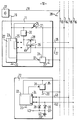
- a multiplex system according to the invention is shown in a figure using a block diagram.
- the figure shows a multiplex system 10 which shows a first subscriber 11 and at least one further subscriber 12, which are connected to power supply lines 13, 14 and to data lines 15, 16.
- an energy source 17 is provided, which is connected to the power supply line 13 via a first connecting line 18 and to the first subscriber 11 via a second connecting line 19.
- the power supply line 13 is connected to a device ground 20.
- the first subscriber 11 contains switching means 21, which connect the second connecting line 19 to the energy supply line 14.
- the switching means 21 are controlled by a signal processing arrangement 22.
- the arrangement 22 contains at least one part 23 which is connected to the energy source 17 via the second connecting line.
- the control signal emitted by the signal processing arrangement 22, 23 for actuating the switching means 21 bears the reference number 24 in the figure.
- the signal processing arrangement 22, 23 contains a signal input and signal output part 25 which is connected to the data lines 15, 16 via two data connection lines 26, 27.
- the data connection lines 26, 27 can also be connected via further switching means 28, 29 to a quiescent energy source 30 which is connected to the second connecting line 19 of the energy source 17.
- the further switching means 28, 29 are controlled by the signal processing arrangement 22, 23.
- the control signal which can be the same for both further switching means 28, 29, is entered in the figure with the reference number 45.
- the first subscriber 11 contains a switching stage 31 with which an electrical consumer (not shown in the figure) can be switched on and off, for example.
- the switching stage 31 is with the Power supply line 14 and connected to the power supply line 13.
- the switching stage 31 is controlled by the signal processing arrangement 22, 23 of the first participant 11.
- the control signal for actuating the switching stage 31 is entered in the figure with the reference symbol 32.
- At least one further subscriber 12 is connected to the lines 13, 14, 15, 16 of the multiplex system 10.
- the subscriber 12 also contains a signal processing arrangement 33, which also has a signal input and signal output part 34.
- the part 34 is connected to the data lines 15, 16 via data exclusion lines 41, 42.
- the further subscriber 12 contains a switching stage 35 for switching an electrical consumer, not shown, on and off.
- the signal processing arrangement 33 and the switching stage 35 are each connected to the power supply lines 13, 14.
- the switching stage 35 is controlled by the arrangement 33.
- the control signal is entered in the figure with the reference symbol 36.
- the further subscriber 12 is assigned means 37 for providing resting energy, which contain two diodes 38, 39 and a capacitor 40.
- the diodes 38, 39 are connected to the data lines 15, 16 via the data connection lines 41, 42.
- the capacitor 40 is connected to ground 20.
- the quiescent energy is available at the common switching point of the diodes 38, 39 and the capacitor 40, which bears the reference symbol 43 in the figure
- the multiplex system 10 contains a plurality of subscribers 11, 12, which can be connected to at least one power supply line 13, 14 and to at least one data line 15, 16.
- the participants 11, 12 are assigned, for example, to electrical consumers or, for example, data sources or data sinks. Are principally all subscribers 11, 12 are connected to both power supply lines 13, 14, with only one line 13, 14 possibly being provided depending on the implementation. In these cases, the other connection to the energy source 17 is established via an existing device mass 20. At least one of the two data lines 15, 16 shown in the figure is also provided.
- the participants 11, 12 can exchange information via the data lines 15, 16. For example, from an operating unit to which a subscriber 11, 12 is assigned, an electrical consumer can be switched on and off, which is connected to another subscriber 11, 12.
- the subscribers 11, 12 can also be assigned data sources and data sinks.
- a data source for example, transducers are provided, which forward the acquired measured values via the data lines 15, 16 to a switching or control device.
- the switching stages 31, 35 which are present, for example, are switched off.
- leakage currents can also occur in the switched-off state of such switching stages 31, 35 or corresponding other arrangements (not shown in the figure) that are assigned to the subscribers 11, 12, which load the energy source 17 in the idle state of the multiplex system 10.
- the first subscriber 11 contains switching means 21 which connect at least one energy supply line 13, 14 to the energy source 17.
- the signal processing arrangement 22, 23 of the first subscriber 11 thus decides on the central power supply of the multiplex system 10.
- the signal processing arrangement 22, 23 controls the switching means 21 with the control signal 24 in dependence on in the arrangement 22, 23 stored information and / or depending on the data received on the data lines 15, 16 via the signal input part 25.
- the power supply of the signal processing arrangement 22 or at least part 23 of the arrangement 22 must therefore always be connected to the energy source 17 at least during the operating time of the multiplex system 10.
- a rest energy supply for individual participants 11, 12 may be required.
- use of the data lines 15, 16 for energy transmission during the inactive state of the multiplex system 10 is therefore provided.
- the control signal 45 causes the further switching means 28, 29 to be actuated.
- the switching means 28, 29 connect the data lines 15, 16 via the data connection lines 26, 27 to the quiescent energy source 30. It is not necessary that the rest energy source 30 can apply the rest energy, it is sufficient if the energy of the energy source 17 is only provided by the rest energy source 30.
- the rest energy is obtained in the further subscribers 12 to be supplied with resting energy by means 37 for providing resting energy, which are connected to the data lines 15, 16 via the data connection lines 41, 42.
- the energy can be taken and fed to the corresponding parts of the subscriber 12, which have a resting energy requirement.
- At least parts of the signal processing arrangement 33 of the further subscriber 12 for example, have such a rest energy requirement, which must be able, for example, to transmit an energy request signal to the first subscriber 11 via the data lines 15, 16.
- the possibility of dispensing a measurement sensor assigned to the further participant 12 must be provided can be reported.
- a quiescent energy is also required, for example, to maintain the memory contents of a data memory of the signal processing arrangement 33 of the subscriber 12.
- the quiescent energy source 30 has a higher potential than is present in the inactive state on the data lines 15, 16.
- a simple decoupling in the means 37 for providing resting energy for separating the means 37 from the data lines 15, 16 is possible during the active state.
- the decoupling occurs when the common circuit point 43, at which the quiescent energy can be drawn, is at a potential during active operation that is greater than or at least equal to the potential on the data lines 15, 16.
- the capacitor 40 is provided for smoothing any AC voltage component that may be present and in particular as an energy store.
- the quiescent energy source 30 has a comparatively high internal resistance.
- the internal resistance is determined in such a way that the signal output part 25, 34 can impress a signal within a predetermined potential range on the data lines 15, 16, which a signal-receiving subscriber 11, 12 recognizes, despite an existing connection of the data lines 15, 16 with the quiescent energy source 30. It is thus possible, at least to a limited extent, to be able to carry out data transmission via the data lines 15, 16 even when the multiplex system 10 is inactive.
- the quiescent energy source 30 can be implemented, for example, as a voltage regulator or in the simplest case as an electrical resistance connected to the energy source 17.
- the switching means 21, 28, 29 are preferably implemented as electronic switches, for example as power field effect transistors.
Applications Claiming Priority (2)
| Application Number | Priority Date | Filing Date | Title |
|---|---|---|---|
| DE4125860 | 1991-08-03 | ||
| DE19914125860 DE4125860C1 (fr) | 1991-08-03 | 1991-08-03 |
Publications (1)
| Publication Number | Publication Date |
|---|---|
| EP0530472A1 true EP0530472A1 (fr) | 1993-03-10 |
Family
ID=6437707
Family Applications (1)
| Application Number | Title | Priority Date | Filing Date |
|---|---|---|---|
| EP92111937A Withdrawn EP0530472A1 (fr) | 1991-08-03 | 1992-07-14 | Système de multiplexage |
Country Status (2)
| Country | Link |
|---|---|
| EP (1) | EP0530472A1 (fr) |
| DE (1) | DE4125860C1 (fr) |
Cited By (4)
| Publication number | Priority date | Publication date | Assignee | Title |
|---|---|---|---|---|
| EP0678643A1 (fr) * | 1994-04-20 | 1995-10-25 | Valeo Electronique | Dispositif de commande de lève-vitres pour véhicule, utilisant un nombre réduit de fils de connexion et intégrant la fonction d'antipincement |
| EP1032160A2 (fr) * | 1999-02-06 | 2000-08-30 | Merten GmbH & Co. KG | Dispositif pour bus de données |
| WO2002076794A2 (fr) * | 2001-03-08 | 2002-10-03 | Siemens Vdo Automotive Corporation | Systeme d'eveil pour composant electronique embarque dans un vehicule |
| CN105579296A (zh) * | 2013-08-19 | 2016-05-11 | 宝马股份公司 | 车辆中的安全相关系统 |
Families Citing this family (2)
| Publication number | Priority date | Publication date | Assignee | Title |
|---|---|---|---|---|
| DE19848880A1 (de) * | 1998-10-23 | 2000-04-27 | Bosch Gmbh Robert | Vorrichtung und Verfahren zur Energieversorgung einer elektrischen Last |
| DE19901196A1 (de) * | 1999-01-14 | 2000-07-20 | Siemens Ag | Verfahren und Einrichtung zur Spannungsversorgung |
Citations (3)
| Publication number | Priority date | Publication date | Assignee | Title |
|---|---|---|---|---|
| EP0327456A1 (fr) * | 1988-02-05 | 1989-08-09 | Siemens Automotive S.A. | Système de mise en état opérationnel et en état de veille de boîtiers électroniques connectés à un canal de communication |
| EP0365435A2 (fr) * | 1988-10-21 | 1990-04-25 | The Furukawa Electric Co., Ltd. | Système de transmission multicanal applicable dans une automobile |
| EP0444997A1 (fr) * | 1990-03-01 | 1991-09-04 | Regie Nationale Des Usines Renault S.A. | Dispositif de commande de l'alimentation À©lectrique d'une pluralité de modules électroniques |
-
1991
- 1991-08-03 DE DE19914125860 patent/DE4125860C1/de not_active Expired - Lifetime
-
1992
- 1992-07-14 EP EP92111937A patent/EP0530472A1/fr not_active Withdrawn
Patent Citations (3)
| Publication number | Priority date | Publication date | Assignee | Title |
|---|---|---|---|---|
| EP0327456A1 (fr) * | 1988-02-05 | 1989-08-09 | Siemens Automotive S.A. | Système de mise en état opérationnel et en état de veille de boîtiers électroniques connectés à un canal de communication |
| EP0365435A2 (fr) * | 1988-10-21 | 1990-04-25 | The Furukawa Electric Co., Ltd. | Système de transmission multicanal applicable dans une automobile |
| EP0444997A1 (fr) * | 1990-03-01 | 1991-09-04 | Regie Nationale Des Usines Renault S.A. | Dispositif de commande de l'alimentation À©lectrique d'une pluralité de modules électroniques |
Non-Patent Citations (1)
| Title |
|---|
| ELECTRONIC ENGINEERING Bd. 55, Nr. 765, 1. März 1983, LONDON GB Seiten 134 - 144 P.E. PHILIPS ET AL. 'Bus systems in the car.' * |
Cited By (8)
| Publication number | Priority date | Publication date | Assignee | Title |
|---|---|---|---|---|
| EP0678643A1 (fr) * | 1994-04-20 | 1995-10-25 | Valeo Electronique | Dispositif de commande de lève-vitres pour véhicule, utilisant un nombre réduit de fils de connexion et intégrant la fonction d'antipincement |
| FR2719075A1 (fr) * | 1994-04-20 | 1995-10-27 | Valeo Electronique | Dispositif de commande de lève-vitres pour véhicule, utilisant un nombre réduit de fils de connexion et intégrant la fonction d'antipincement. |
| EP1032160A2 (fr) * | 1999-02-06 | 2000-08-30 | Merten GmbH & Co. KG | Dispositif pour bus de données |
| EP1032160A3 (fr) * | 1999-02-06 | 2003-04-23 | Merten GmbH & Co. KG | Dispositif pour bus de données |
| WO2002076794A2 (fr) * | 2001-03-08 | 2002-10-03 | Siemens Vdo Automotive Corporation | Systeme d'eveil pour composant electronique embarque dans un vehicule |
| WO2002076794A3 (fr) * | 2001-03-08 | 2003-03-20 | Siemens Vdo Automotive Corp | Systeme d'eveil pour composant electronique embarque dans un vehicule |
| US6838783B2 (en) | 2001-03-08 | 2005-01-04 | Siemens Vdo Automotive Corporation | Wake up system for electronic component supported on a vehicle |
| CN105579296A (zh) * | 2013-08-19 | 2016-05-11 | 宝马股份公司 | 车辆中的安全相关系统 |
Also Published As
| Publication number | Publication date |
|---|---|
| DE4125860C1 (fr) | 1992-08-06 |
Similar Documents
| Publication | Publication Date | Title |
|---|---|---|
| DE3901636C2 (fr) | ||
| EP0393233B1 (fr) | Système de transmission de signaux | |
| EP0884821A1 (fr) | Système de distribution d'énergie, en particulier pour un aéronef | |
| EP0261319A2 (fr) | Disposition de circuit pour produire une tension alternative | |
| DE4125860C1 (fr) | ||
| EP0437697A2 (fr) | Combinaison d'appareils | |
| DE19914004B4 (de) | Identifizierbares elektrisches Bauteil mit Verfahren zur Identifikation und Auswerteeinheit | |
| DE69932667T2 (de) | Batterieumschaltung fur eine Teilnehmerleitungsschnittstellenschaltung | |
| EP0461432A2 (fr) | Dispositif pour brancher et débrancher une charge | |
| DE19947501B4 (de) | Aktuator-Sensor-Interface-Slave | |
| EP0643515B1 (fr) | Dispositif pour la transmission bidirectionnelle de données | |
| DE102017202295A1 (de) | Schaltungsanordnung zum Durchführen eines Vergleichs | |
| EP1192551B1 (fr) | Interface pour coupler un noeud de bus a la ligne bus d'un systeme bus | |
| DE19647131C2 (de) | Vorrichtung und Verfahren zur zeitmultiplexen Übertragung von Informationen | |
| DE3807418A1 (de) | Datenbus fuer kraftfahrzeuge | |
| EP0735493A1 (fr) | Circuit d'attaque de bus | |
| EP0500693B1 (fr) | Procede et dispositif d'activation d'une carte a memoire | |
| EP0972134A1 (fr) | Dispositif pour reguler le passage d'un courant a travers un consommateur | |
| EP1019881B1 (fr) | Unite d'entree numerique avec moyens de reconnaissance de ruptures de fils | |
| DE102005044004B3 (de) | Stellvorrichtung für eine mechanische Komponente und Steuervorrichtung | |
| EP0093899B1 (fr) | Circuit pour l'adaptation d'un dispositif d'essai à un objet à l'essai | |
| EP0840229A2 (fr) | Dispositif et méthode de sélection de mots d'adresse | |
| DE10111468B4 (de) | Verfahren und Vorrichtung zur Ermittlung von Eigenschaften gesteckter Module | |
| DE3537399A1 (de) | Periphere interface-einheit | |
| DE3100960A1 (de) | Elektrische leistungsversorgungsvorrichtung |
Legal Events
| Date | Code | Title | Description |
|---|---|---|---|
| PUAI | Public reference made under article 153(3) epc to a published international application that has entered the european phase |
Free format text: ORIGINAL CODE: 0009012 |
|
| AK | Designated contracting states |
Kind code of ref document: A1 Designated state(s): DE FR GB IT |
|
| 17P | Request for examination filed |
Effective date: 19930821 |
|
| STAA | Information on the status of an ep patent application or granted ep patent |
Free format text: STATUS: THE APPLICATION IS DEEMED TO BE WITHDRAWN |
|
| 18D | Application deemed to be withdrawn |
Effective date: 19980203 |