EP0529785B1 - Raster output scanner with process direction spot position control - Google Patents
Raster output scanner with process direction spot position control Download PDFInfo
- Publication number
- EP0529785B1 EP0529785B1 EP92306288A EP92306288A EP0529785B1 EP 0529785 B1 EP0529785 B1 EP 0529785B1 EP 92306288 A EP92306288 A EP 92306288A EP 92306288 A EP92306288 A EP 92306288A EP 0529785 B1 EP0529785 B1 EP 0529785B1
- Authority
- EP
- European Patent Office
- Prior art keywords
- light beam
- photoreceptor
- process direction
- generating
- cylindrical lens
- Prior art date
- Legal status (The legal status is an assumption and is not a legal conclusion. Google has not performed a legal analysis and makes no representation as to the accuracy of the status listed.)
- Expired - Lifetime
Links
Images

Classifications
-
- H—ELECTRICITY
- H04—ELECTRIC COMMUNICATION TECHNIQUE
- H04N—PICTORIAL COMMUNICATION, e.g. TELEVISION
- H04N1/00—Scanning, transmission or reproduction of documents or the like, e.g. facsimile transmission; Details thereof
- H04N1/04—Scanning arrangements, i.e. arrangements for the displacement of active reading or reproducing elements relative to the original or reproducing medium, or vice versa
- H04N1/047—Detection, control or error compensation of scanning velocity or position
- H04N1/0473—Detection, control or error compensation of scanning velocity or position in subscanning direction, e.g. picture start or line-to-line synchronisation
-
- G—PHYSICS
- G06—COMPUTING; CALCULATING OR COUNTING
- G06K—GRAPHICAL DATA READING; PRESENTATION OF DATA; RECORD CARRIERS; HANDLING RECORD CARRIERS
- G06K15/00—Arrangements for producing a permanent visual presentation of the output data, e.g. computer output printers
- G06K15/02—Arrangements for producing a permanent visual presentation of the output data, e.g. computer output printers using printers
- G06K15/12—Arrangements for producing a permanent visual presentation of the output data, e.g. computer output printers using printers by photographic printing, e.g. by laser printers
- G06K15/1204—Arrangements for producing a permanent visual presentation of the output data, e.g. computer output printers using printers by photographic printing, e.g. by laser printers involving the fast moving of an optical beam in the main scanning direction
- G06K15/1219—Detection, control or error compensation of scanning velocity or position, e.g. synchronisation
-
- H—ELECTRICITY
- H04—ELECTRIC COMMUNICATION TECHNIQUE
- H04N—PICTORIAL COMMUNICATION, e.g. TELEVISION
- H04N1/00—Scanning, transmission or reproduction of documents or the like, e.g. facsimile transmission; Details thereof
- H04N1/04—Scanning arrangements, i.e. arrangements for the displacement of active reading or reproducing elements relative to the original or reproducing medium, or vice versa
- H04N1/113—Scanning arrangements, i.e. arrangements for the displacement of active reading or reproducing elements relative to the original or reproducing medium, or vice versa using oscillating or rotating mirrors
- H04N1/1135—Scanning arrangements, i.e. arrangements for the displacement of active reading or reproducing elements relative to the original or reproducing medium, or vice versa using oscillating or rotating mirrors for the main-scan only
-
- H—ELECTRICITY
- H04—ELECTRIC COMMUNICATION TECHNIQUE
- H04N—PICTORIAL COMMUNICATION, e.g. TELEVISION
- H04N1/00—Scanning, transmission or reproduction of documents or the like, e.g. facsimile transmission; Details thereof
- H04N1/04—Scanning arrangements, i.e. arrangements for the displacement of active reading or reproducing elements relative to the original or reproducing medium, or vice versa
- H04N1/12—Scanning arrangements, i.e. arrangements for the displacement of active reading or reproducing elements relative to the original or reproducing medium, or vice versa using the sheet-feed movement or the medium-advance or the drum-rotation movement as the slow scanning component, e.g. arrangements for the main-scanning
-
- H—ELECTRICITY
- H04—ELECTRIC COMMUNICATION TECHNIQUE
- H04N—PICTORIAL COMMUNICATION, e.g. TELEVISION
- H04N2201/00—Indexing scheme relating to scanning, transmission or reproduction of documents or the like, and to details thereof
- H04N2201/024—Indexing scheme relating to scanning, transmission or reproduction of documents or the like, and to details thereof deleted
- H04N2201/02406—Arrangements for positioning elements within a head
- H04N2201/02439—Positioning method
-
- H—ELECTRICITY
- H04—ELECTRIC COMMUNICATION TECHNIQUE
- H04N—PICTORIAL COMMUNICATION, e.g. TELEVISION
- H04N2201/00—Indexing scheme relating to scanning, transmission or reproduction of documents or the like, and to details thereof
- H04N2201/04—Scanning arrangements
- H04N2201/047—Detection, control or error compensation of scanning velocity or position
- H04N2201/04701—Detection of scanning velocity or position
- H04N2201/0471—Detection of scanning velocity or position using dedicated detectors
-
- H—ELECTRICITY
- H04—ELECTRIC COMMUNICATION TECHNIQUE
- H04N—PICTORIAL COMMUNICATION, e.g. TELEVISION
- H04N2201/00—Indexing scheme relating to scanning, transmission or reproduction of documents or the like, and to details thereof
- H04N2201/04—Scanning arrangements
- H04N2201/047—Detection, control or error compensation of scanning velocity or position
- H04N2201/04701—Detection of scanning velocity or position
- H04N2201/04715—Detection of scanning velocity or position by detecting marks or the like, e.g. slits
- H04N2201/04722—Detection of scanning velocity or position by detecting marks or the like, e.g. slits on a photoconductive drum or belt
-
- H—ELECTRICITY
- H04—ELECTRIC COMMUNICATION TECHNIQUE
- H04N—PICTORIAL COMMUNICATION, e.g. TELEVISION
- H04N2201/00—Indexing scheme relating to scanning, transmission or reproduction of documents or the like, and to details thereof
- H04N2201/04—Scanning arrangements
- H04N2201/047—Detection, control or error compensation of scanning velocity or position
- H04N2201/04701—Detection of scanning velocity or position
- H04N2201/04729—Detection of scanning velocity or position in the main-scan direction
-
- H—ELECTRICITY
- H04—ELECTRIC COMMUNICATION TECHNIQUE
- H04N—PICTORIAL COMMUNICATION, e.g. TELEVISION
- H04N2201/00—Indexing scheme relating to scanning, transmission or reproduction of documents or the like, and to details thereof
- H04N2201/04—Scanning arrangements
- H04N2201/047—Detection, control or error compensation of scanning velocity or position
- H04N2201/04701—Detection of scanning velocity or position
- H04N2201/04734—Detecting at frequent intervals, e.g. once per line for sub-scan control
-
- H—ELECTRICITY
- H04—ELECTRIC COMMUNICATION TECHNIQUE
- H04N—PICTORIAL COMMUNICATION, e.g. TELEVISION
- H04N2201/00—Indexing scheme relating to scanning, transmission or reproduction of documents or the like, and to details thereof
- H04N2201/04—Scanning arrangements
- H04N2201/047—Detection, control or error compensation of scanning velocity or position
- H04N2201/04701—Detection of scanning velocity or position
- H04N2201/04744—Detection of scanning velocity or position by detecting the scanned beam or a reference beam
-
- H—ELECTRICITY
- H04—ELECTRIC COMMUNICATION TECHNIQUE
- H04N—PICTORIAL COMMUNICATION, e.g. TELEVISION
- H04N2201/00—Indexing scheme relating to scanning, transmission or reproduction of documents or the like, and to details thereof
- H04N2201/04—Scanning arrangements
- H04N2201/047—Detection, control or error compensation of scanning velocity or position
- H04N2201/04753—Control or error compensation of scanning position or velocity
- H04N2201/04758—Control or error compensation of scanning position or velocity by controlling the position of the scanned image area
- H04N2201/0476—Control or error compensation of scanning position or velocity by controlling the position of the scanned image area using an optical, electro-optical or acousto-optical element
-
- H—ELECTRICITY
- H04—ELECTRIC COMMUNICATION TECHNIQUE
- H04N—PICTORIAL COMMUNICATION, e.g. TELEVISION
- H04N2201/00—Indexing scheme relating to scanning, transmission or reproduction of documents or the like, and to details thereof
- H04N2201/04—Scanning arrangements
- H04N2201/047—Detection, control or error compensation of scanning velocity or position
- H04N2201/04753—Control or error compensation of scanning position or velocity
- H04N2201/04794—Varying the control or compensation during the scan, e.g. using continuous feedback or from line to line
Definitions
- This invention relates generally to a raster output scanning system for producing a high intensity imaging beam which scans across a movable photoconductive member to record electrostatic latent images thereon.
- a raster output scanner has a laser for generating a collimated beam of monochromatic radiation.
- the laser beam is modulated in conformance with the image information.
- the modulated beam is reflected through a lens onto a scanning element, typically a rotating polygon having mirrored facets.
- the light beam is reflected from a facet and thereafter focused to a "spot" on the photosensitive member.
- the rotation of the polygon causes the spot to scan linearly across the photoconductive member in a fast scan (i.e., line scan) direction.
- the photoconductive member is advanced relatively more slowly than the rate of the fast scan in a slow scan direction which is orthogonal to the fast scan direction.
- the beam scans the recording medium in a raster scanning pattern.
- the light beam is intensity-modulated in accordance with an input image serial data stream at a rate such that individual picture elements ("pixels") of the image represented by the data stream are exposed on the photosensitive medium to form a latent image, which is then transferred to an appropriate image receiving medium such as paper.
- the sampling rate of the slow scan direction data equates to 300 lines per inch or more in many printing apparatus. It has been shown that errors in the slow scan direction of as small as 1% of the nominal line spacing may be perceived in a half tone or continuous tone image. This implies a need for a high degree of control in positioning the spot in the slow scan direction on the image plane, especially in such applications as multiple beam and multiple ROS colour printers where a plurality of spots are written onto a single photoreceptor. Furthermore, high resolution printing, on the order of 600 spots per inch or higher, demands very accurate spot positioning.
- Errors of the spot position in the slow scan direction arise from many sources, including polygon and/or photosensitive member motion flaws, facet and/or image plane (e.g., photosensitive medium) surface defects, etc.
- these errors are most commonly addressed by passive or active in-line optics as disclosed in, for example, U. S. Patent US-A-4,600,837 and U. S. Patent US-A-4,660,094.
- high quality optical elements are required, together with tight control in the positioning of those optics, in order to obtain the requisite very precise mechanical control sufficient to adjust spot position by .02 mm or less, as required in many cases. It is an object of the present invention to enable that disadvantage to be overcome.
- US-A-4,453,170 discloses an image forming apparatus for recording information on a moving photosensitive member with a light beam from a laser beam generator.
- the light beam is intensity modulated and caused to scan across the photosensitive member by a rotating polygon mirror.
- the scanning light beam is passed through a correction lens and reflected onto and from a fixed mirror onto the photosensitive member. Vibration of the light beam is corrected at the fixed mirror by sensor and actuator shown in Figures 10 and 11.
- JP-A-3,120,509 discloses an image forming apparatus for recording information on a plane to be scanned with a laser beam from a laser reflected from a rotary polygonal mirror.
- an electromagnetic actuator which displaces a lens is located at the laser or between the laser and the polygonal mirrors.
- the electromagnetic actuator has a piezoelectric actuator which displaces the laser or the lens in a subscan direction.
- JP-A-2 163 721 discloses correction of a shift in an image plane position in the subscanning direction by varying the refractive power of a stationary cylindrical lens.
- the ROS system includes a cylinder lens in the pre-polygon optics to focus the beam in the slow scan direction onto the polygon facets.
- the cylinder lens a relatively light optical component in the pre-polygon optical path, is adapted to be moved in the plane parallel to the process direction plane, so as to correct the location of the scanned beams at the photoreceptor.
- the correction may be enabled by providing a phase error feedback circuit for generating error signals which may be sent to a pizeo-electric actuator to provide high frequency control in the process direction of the position of the cylinder lens.
- the present invention relates to a laser printer apparatus of the type which forms an image on a surface of a movable photoreceptor in response to an image data signal, comprising: means for moving the photoreceptor in a process direction, a laser source for generating a coherent light beam along an optical path, modulating means for modulating the light beam generated by said light source in response to said image data signal, scanning means for scanning the light beam produced by said light source and modulated by said modulating means onto the surface of said photoreceptor in a raster fashion and scan direction perpendicular to the process direction, characterized by: a cylindrical lens adjustable in the process direction and disposed in the optical path between the laser source and the scanning means; error detection and feedback control circuit for generating an error signal representative of a detected light beam positional error on the surface of the photoreceptor in the process direction at the point that the light beam is incident upon the photoreceptor surface; and actuator means for adjusting the cylindrical lens in the process direction in response to the error signal received from the control circuit to reposition
- FIG. 1 shows a side view of the general optical configuration of a Raster Output Scanner (ROS) system.
- ROS Raster Output Scanner
- FIG. 2 shows a top or plan view of the ROS system of FIG. 1.
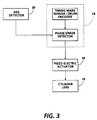
- FIG. 3 shows a flow diagram illustrating the control for regulating the position of the cylinder lens shown in FIG. 1.
- FIGS. 1 and 2 show a side and top schematic view, respectively, of a ROS system.
- Input video data is transmitted to a self-modulating light source 12, such as a low powered solid state laser diode, which produces a modulated diverging beam of coherent light.
- the beam is collimated by a spherical collimating lens 14 and enters cylindrical lens 16.
- Cylindrical lens 16 serves to focus the beam in the slow scan (process) direction.
- Lens 16 is movable in the process direction by a pizeo-electric actuator 18 in response to motion error signals sent to actuator 18 from error feedback circuit 19 described in further detail below.
- the beam is next incident upon a rotating polygon 20 having at least one mirrored facet 21.
- a rotating polygon 20 having at least one mirrored facet 21.
- suitable devices for scanning include rotating hologons, rotating diffraction gratings, etc..
- the rotation of the mirrored facets causes the beam to be deflected and thereby scanned across a photosensitive image member which in a preferred embodiment is a photoreceptor drum 24.
- the ROS illuminates the charged portion of drum 24 at a rate of about 400 pixels per inch; e.g. at 400 spi resolution.
- postscan optics system 22 reconfigures the beam reflected by facet 21 to a circular or elliptical cross-section, refocuses the beam to the proper point on the surface of photoreceptor/drum 24, and corrects for scan nonlinearity (f-theta correction).
- a 1X (or other working magnification) toroidal lens 28 is disposed between the scanning device 20 and the photoreceptor 24 to correct for wobble (scanner motion or facet errors) where appropriate.
- FIG. 1 is a view of system 10 oriented so that the process direction is parallel to, or in the plane of the page on which the figure is printed, while the fast scan direction is perpendicular to the plane of the page.
- FIG. 2 if polygon 20 is rotated in a clockwise fashion, as shown in FIG. 2, a beam reflected from one of its moving facets will be caused to scan from left to right on the photoreceptive drum 24.
- scanning may proceed in a top to bottom, raster manner.
- Polygon 20 is preferably driven by a motor 23 through a shaft, with the angular velocity of polygon 20 synchronised with the angular velocity of drum 24.
- cylinder lens 16 controls the location of the spot of the photoreceptor surface in the slow scan process direction.
- the cylinder lens is moved in the process direction, it will move the location of the scanned spot in the same direction and in an amount dependent on system magnification.
- the cylinder lens is moved one micron in a vertical direction in FIG. 1, the image at the polygon facet 21 will move one micron in the same direction. Since the polygon facet is imaged at the photoreceptor surface, the spot will move at the photoreceptor an amount dependent on the magnification of the wobble correcting system (lens 28). For a 1X lens 28, the spot would move one micron at the photoreceptor.
- FIG. 3 illustrates one embodiment of an error detection and feedback control circuit for determining the existence and extent of the rotational error of drum 24 and for controlling the operation of actuator 18 so as to move lens 16 the required distance to correct the error.
- FIG. 2 shows a start of scan (SOS) sensor 30 positioned adjacent to the photoreceptor drum.
- SOS start of scan
- the sensor emits signals at a frequency equal to the system slow scan resolution, e.g. 4000Hz for a 10 ips process speed with 400 Ipi slow scan resolution.
- a set of timing marks, 34, spaced 1/400th of an inch apart, or some other appropriate spacing are located along the side of the drum. These timing marks are sensed by a light source/detector combination and provide the basic timing signals for the synchronisation of the control system.
- the timing signals can be generated by a shaft encoder mounted on the photoreceptor drum shaft.
- a phase detector detects the phase difference between the signal from the SOS detector 30 and the timing marks on the drum and generates a phase error voltage that represents the phase error and polarity.
- This signal is fed to pizeoelectric actuator 18 which transmits the induced, mechanical motion to the cylinder lens 16 to make the necessary process direction correction.
- Actuator 18, in a preferred embodiment, is a Burleigh model PLZ-020.
- the cylinder lens When the cylinder lens is moved in the process direction, perpendicular to the optical axis, a slightly different portion of the collimated beam is selected at each location.
- the cylinder lens By making the diameter of the collimated beam slightly larger than the aperture of the cylinder lens, the cylinder lens will always be the limiting aperture in the system. Since the cylinder lens is moving such a small distance ( ⁇ .02mm), the effect of selecting different sections of the collimated beam on photoreceptor exposure will be negligible.
- An error correction arrangement as described above is especially, but not exclusively, intended to provide compensation for photoreceptor motion (vibration) errors in the range of approximately 0 - 150hz.
Landscapes
- Engineering & Computer Science (AREA)
- Multimedia (AREA)
- Signal Processing (AREA)
- Physics & Mathematics (AREA)
- Optics & Photonics (AREA)
- General Engineering & Computer Science (AREA)
- General Physics & Mathematics (AREA)
- Theoretical Computer Science (AREA)
- Mechanical Optical Scanning Systems (AREA)
- Facsimile Scanning Arrangements (AREA)
- Laser Beam Printer (AREA)
- Dot-Matrix Printers And Others (AREA)
Description
- This invention relates generally to a raster output scanning system for producing a high intensity imaging beam which scans across a movable photoconductive member to record electrostatic latent images thereon.
- In recent years, laser printers have been increasingly utilised to produce output copies from input video data representing original image information. The printer uses a raster output scanner (ROS) to expose the charged portions of the photoconductive member to record the electrostatic latent image thereon. Generally, a raster output scanner has a laser for generating a collimated beam of monochromatic radiation. The laser beam is modulated in conformance with the image information. The modulated beam is reflected through a lens onto a scanning element, typically a rotating polygon having mirrored facets. The light beam is reflected from a facet and thereafter focused to a "spot" on the photosensitive member. The rotation of the polygon causes the spot to scan linearly across the photoconductive member in a fast scan (i.e., line scan) direction. Meanwhile, the photoconductive member is advanced relatively more slowly than the rate of the fast scan in a slow scan direction which is orthogonal to the fast scan direction. In this way, the beam scans the recording medium in a raster scanning pattern. The light beam is intensity-modulated in accordance with an input image serial data stream at a rate such that individual picture elements ("pixels") of the image represented by the data stream are exposed on the photosensitive medium to form a latent image, which is then transferred to an appropriate image receiving medium such as paper.
- Data in each of the fast and slow scan directions is generally sampled. The sampling rate of the slow scan direction data equates to 300 lines per inch or more in many printing apparatus. It has been shown that errors in the slow scan direction of as small as 1% of the nominal line spacing may be perceived in a half tone or continuous tone image. This implies a need for a high degree of control in positioning the spot in the slow scan direction on the image plane, especially in such applications as multiple beam and multiple ROS colour printers where a plurality of spots are written onto a single photoreceptor. Furthermore, high resolution printing, on the order of 600 spots per inch or higher, demands very accurate spot positioning.
- Errors of the spot position in the slow scan direction arise from many sources, including polygon and/or photosensitive member motion flaws, facet and/or image plane (e.g., photosensitive medium) surface defects, etc. In the prior art, these errors are most commonly addressed by passive or active in-line optics as disclosed in, for example, U. S. Patent US-A-4,600,837 and U. S. Patent US-A-4,660,094. However, high quality optical elements are required, together with tight control in the positioning of those optics, in order to obtain the requisite very precise mechanical control sufficient to adjust spot position by .02 mm or less, as required in many cases. It is an object of the present invention to enable that disadvantage to be overcome.
- US-A-4,453,170 discloses an image forming apparatus for recording information on a moving photosensitive member with a light beam from a laser beam generator. The light beam is intensity modulated and caused to scan across the photosensitive member by a rotating polygon mirror. The scanning light beam is passed through a correction lens and reflected onto and from a fixed mirror onto the photosensitive member. Vibration of the light beam is corrected at the fixed mirror by sensor and actuator shown in Figures 10 and 11.
- JP-A-3,120,509 discloses an image forming apparatus for recording information on a plane to be scanned with a laser beam from a laser reflected from a rotary polygonal mirror. To provide a large amount of displacement of the laser beam on the plane to be scanned,an electromagnetic actuator which displaces a lens is located at the laser or between the laser and the polygonal mirrors. The electromagnetic actuator has a piezoelectric actuator which displaces the laser or the lens in a subscan direction.
- JP-A-2 163 721 discloses correction of a shift in an image plane position in the subscanning direction by varying the refractive power of a stationary cylindrical lens.
- According to the present invention, the ROS system includes a cylinder lens in the pre-polygon optics to focus the beam in the slow scan direction onto the polygon facets. The cylinder lens, a relatively light optical component in the pre-polygon optical path, is adapted to be moved in the plane parallel to the process direction plane, so as to correct the location of the scanned beams at the photoreceptor. The correction may be enabled by providing a phase error feedback circuit for generating error signals which may be sent to a pizeo-electric actuator to provide high frequency control in the process direction of the position of the cylinder lens.
- More particularly the present invention relates to a laser printer apparatus of the type which forms an image on a surface of a movable photoreceptor in response to an image data signal, comprising: means for moving the photoreceptor in a process direction, a laser source for generating a coherent light beam along an optical path, modulating means for modulating the light beam generated by said light source in response to said image data signal, scanning means for scanning the light beam produced by said light source and modulated by said modulating means onto the surface of said photoreceptor in a raster fashion and scan direction perpendicular to the process direction, characterized by: a cylindrical lens adjustable in the process direction and disposed in the optical path between the laser source and the scanning means; error detection and feedback control circuit for generating an error signal representative of a detected light beam positional error on the surface of the photoreceptor in the process direction at the point that the light beam is incident upon the photoreceptor surface; and actuator means for adjusting the cylindrical lens in the process direction in response to the error signal received from the control circuit to reposition the cylindrical lens and thereby correct the light beam positional error.
- By way of example only, an embodiment of the invention will be described with reference to the accompanying drawings, in which :
- FIG. 1 shows a side view of the general optical configuration of a Raster Output Scanner (ROS) system.
- FIG. 2 shows a top or plan view of the ROS system of FIG. 1.
- FIG. 3 shows a flow diagram illustrating the control for regulating the position of the cylinder lens shown in FIG. 1.
- FIGS. 1 and 2 show a side and top schematic view, respectively, of a ROS system. Input video data is transmitted to a self-modulating
light source 12, such as a low powered solid state laser diode, which produces a modulated diverging beam of coherent light. The beam is collimated by a spherical collimatinglens 14 and enterscylindrical lens 16.Cylindrical lens 16 serves to focus the beam in the slow scan (process) direction.Lens 16 is movable in the process direction by a pizeo-electric actuator 18 in response to motion error signals sent toactuator 18 fromerror feedback circuit 19 described in further detail below. - The beam is next incident upon a rotating
polygon 20 having at least one mirroredfacet 21. (Other suitable devices for scanning include rotating hologons, rotating diffraction gratings, etc..) As shown most clearly in FIG. 2, the rotation of the mirrored facets causes the beam to be deflected and thereby scanned across a photosensitive image member which in a preferred embodiment is aphotoreceptor drum 24. The ROS illuminates the charged portion ofdrum 24 at a rate of about 400 pixels per inch; e.g. at 400 spi resolution. - Returning to FIG. 1,
postscan optics system 22 reconfigures the beam reflected byfacet 21 to a circular or elliptical cross-section, refocuses the beam to the proper point on the surface of photoreceptor/drum 24, and corrects for scan nonlinearity (f-theta correction). A 1X (or other working magnification)toroidal lens 28 is disposed between thescanning device 20 and thephotoreceptor 24 to correct for wobble (scanner motion or facet errors) where appropriate. - FIG. 1 is a view of
system 10 oriented so that the process direction is parallel to, or in the plane of the page on which the figure is printed, while the fast scan direction is perpendicular to the plane of the page. The opposite is true for FIG. 2. Thus, ifpolygon 20 is rotated in a clockwise fashion, as shown in FIG. 2, a beam reflected from one of its moving facets will be caused to scan from left to right on thephotoreceptive drum 24. By combining this rotation ofpolygon 20 with rotation of thephotoreceptor drum 24 in a clockwise fashion, as shown in FIG. 1, scanning may proceed in a top to bottom, raster manner. Polygon 20 is preferably driven by amotor 23 through a shaft, with the angular velocity ofpolygon 20 synchronised with the angular velocity ofdrum 24. - It is evident from the above description that
cylinder lens 16 controls the location of the spot of the photoreceptor surface in the slow scan process direction. Thus, if the cylinder lens is moved in the process direction, it will move the location of the scanned spot in the same direction and in an amount dependent on system magnification. For example, if the cylinder lens is moved one micron in a vertical direction in FIG. 1, the image at thepolygon facet 21 will move one micron in the same direction. Since the polygon facet is imaged at the photoreceptor surface, the spot will move at the photoreceptor an amount dependent on the magnification of the wobble correcting system (lens 28). For a1X lens 28, the spot would move one micron at the photoreceptor. - FIG. 3 illustrates one embodiment of an error detection and feedback control circuit for determining the existence and extent of the rotational error of
drum 24 and for controlling the operation ofactuator 18 so as to movelens 16 the required distance to correct the error. - Referring to FIGS. 2 and 3, FIG. 2 shows a start of scan (SOS)
sensor 30 positioned adjacent to the photoreceptor drum. Each time a scanning beam sweeps across the drum surface and passes oversensor 30, a start of scan signal is emitted. The sensor emits signals at a frequency equal to the system slow scan resolution, e.g. 4000Hz for a 10 ips process speed with 400 Ipi slow scan resolution. A set of timing marks, 34, spaced 1/400th of an inch apart, or some other appropriate spacing are located along the side of the drum. These timing marks are sensed by a light source/detector combination and provide the basic timing signals for the synchronisation of the control system. Alternatively, the timing signals can be generated by a shaft encoder mounted on the photoreceptor drum shaft. - As the beam scans across the
SOS detector 30, it generates timing pulses. The beam is initially aligned and adjusted with some relationship to the occurrences of the drum timing marks. A phase detector detects the phase difference between the signal from theSOS detector 30 and the timing marks on the drum and generates a phase error voltage that represents the phase error and polarity. This signal is fed topizeoelectric actuator 18 which transmits the induced, mechanical motion to thecylinder lens 16 to make the necessary process direction correction.Actuator 18, in a preferred embodiment, is a Burleigh model PLZ-020. - When the cylinder lens is moved in the process direction, perpendicular to the optical axis, a slightly different portion of the collimated beam is selected at each location. By making the diameter of the collimated beam slightly larger than the aperture of the cylinder lens, the cylinder lens will always be the limiting aperture in the system. Since the cylinder lens is moving such a small distance (<.02mm), the effect of selecting different sections of the collimated beam on photoreceptor exposure will be negligible.
- An error correction arrangement as described above is especially, but not exclusively, intended to provide compensation for photoreceptor motion (vibration) errors in the range of approximately 0 - 150hz.
Claims (5)
- Laser printer apparatus (10) of the type which forms an image on a surface of a movable photoreceptor (24) in response to an image data signal, comprising:means for moving the photoreceptor in a process direction,a laser source (12) for generating a coherent light beam along an optical path,modulating means for modulating the light beam generated by said light source in response to said image data signal,scanning means (20) for scanning the light beam produced by said light source and modulated by said modulating means onto the surface of said photoreceptor in a raster fashion and in a scan direction perpendicular to the process direction, characterized by:a cylindrical lens (16) positionally adjustable in the process direction and disposed in the optical path between the laser source and the scanning means;error detection and feedback control circuit (19, 30) for generating an error signal representative of a detected light beam positional error on the surface of the photoreceptor in the process direction at the point that the light beam is incident upon the photoreceptor surface; andactuator means (18) for adjusting the cylindrical lens position in the process direction in response to the error signal received from the control circuit to reposition the cylindrical lens and thereby correct the light beam positional error.
- Apparatus as claimed in claim 1, wherein the error detection and feedback control circuit includes a start of scan sensor (30), which emits a start of scan signal each time a light beam sweeps across the photoreceptor surface, and means (34) for generating timing signals for the synchronization of the control circuit; and wherein the photoreceptor is a drum rotated about a shaft.
- Apparatus as claimed in claim 2, wherein the means for generating timing signals is a set of timing marks (34) and a light source/detector for sensing the timing marks and generating the timing signals or a shaft encoder mounted on a shaft of the photoreceptor drum for generating the timing signals.
- Apparatus as claimed in any of the preceding claims, wherein the actuator means is a piezoelectric actuator; and wherein the lens has an aperture with a predetermined size.
- Apparatus as claimed in claim 4, wherein the apparatus further includes a collimating lens (14) located in the optical path of the light beam generated by the laser source and positioned between the laser source and cylindrical lens to collimate the light beam into a light beam having a diameter larger than the aperture of the cylindrical lens, so that the repositioning of the cylindrical lens effects the selection of different sections of the collimated beam from said collimating lens.
Applications Claiming Priority (2)
| Application Number | Priority Date | Filing Date | Title |
|---|---|---|---|
| US07/740,543 US5287125A (en) | 1991-08-05 | 1991-08-05 | Raster output scanner with process direction spot position control |
| US740543 | 1991-08-05 |
Publications (2)
| Publication Number | Publication Date |
|---|---|
| EP0529785A1 EP0529785A1 (en) | 1993-03-03 |
| EP0529785B1 true EP0529785B1 (en) | 1997-10-08 |
Family
ID=24976966
Family Applications (1)
| Application Number | Title | Priority Date | Filing Date |
|---|---|---|---|
| EP92306288A Expired - Lifetime EP0529785B1 (en) | 1991-08-05 | 1992-07-09 | Raster output scanner with process direction spot position control |
Country Status (5)
| Country | Link |
|---|---|
| US (1) | US5287125A (en) |
| EP (1) | EP0529785B1 (en) |
| JP (1) | JPH05246073A (en) |
| CA (1) | CA2067887C (en) |
| DE (1) | DE69222604T2 (en) |
Families Citing this family (16)
| Publication number | Priority date | Publication date | Assignee | Title |
|---|---|---|---|---|
| EP0506410A3 (en) * | 1991-03-26 | 1993-09-01 | Kabushiki Kaisha Toshiba | Scanning optical apparatus |
| US5627579A (en) * | 1994-11-29 | 1997-05-06 | Xerox Corporation | Raster scanning optical system and method for adjusting scan line locations on a photoreceptor |
| US6133932A (en) * | 1994-12-19 | 2000-10-17 | Xerox Corporation | Method and apparatus for adjusting a line synchronization signal in response to photoreceptor motion |
| US5646394A (en) * | 1995-03-16 | 1997-07-08 | Hewlett-Packard Company | Imaging device with beam steering capability |
| US5889545A (en) * | 1996-07-01 | 1999-03-30 | Xerox Corporation | Method and apparatus for image registration in a single pass ROS printer using a rotatable output window with no optical power |
| JPH10181096A (en) * | 1996-12-06 | 1998-07-07 | Xerox Corp | Raster output scanning apparatus |
| US5933182A (en) * | 1998-01-08 | 1999-08-03 | Xerox Corporation | Single pass color printer with facet matching |
| US6055005A (en) * | 1998-01-08 | 2000-04-25 | Xerox Corporation | Color printer with jitter signature matching |
| US6144478A (en) * | 1998-12-11 | 2000-11-07 | Xerox Corporation | Flexible arm piezoelectric lens mover |
| US6141031A (en) * | 1998-12-11 | 2000-10-31 | Xerox Corporation | Aerial color registration |
| US6226029B1 (en) * | 1999-04-26 | 2001-05-01 | Xerox Corporation | Aerial slow scan position control using an electronically addressable liquid crystal plate |
| US6469729B1 (en) | 1999-10-15 | 2002-10-22 | Videojet Technologies Inc. | Laser marking device and method for marking arcuate surfaces |
| US6608643B2 (en) | 2002-01-16 | 2003-08-19 | Xerox Corporation | Systems and method for measuring or reducing spacing errors in multiple beam ROS systems |
| JP2008254035A (en) * | 2007-04-05 | 2008-10-23 | Disco Abrasive Syst Ltd | Laser beam machining apparatus |
| US7542200B1 (en) | 2007-12-21 | 2009-06-02 | Palo Alto Research Center Incorporated | Agile beam steering mirror for active raster scan error correction |
| TW201013222A (en) * | 2008-09-23 | 2010-04-01 | E Pin Optical Industry Co Ltd | Two optical elements fθ lens of MEMS laser scanning unit 8 |
Family Cites Families (11)
| Publication number | Priority date | Publication date | Assignee | Title |
|---|---|---|---|---|
| US4040096A (en) * | 1972-11-27 | 1977-08-02 | Xerox Corporation | Flying spot scanner with runout correction |
| US4121883A (en) * | 1974-04-22 | 1978-10-24 | Canon Kabushiki Kaisha | Scanning device for radiation beams |
| DE3046584C2 (en) * | 1980-12-11 | 1984-03-15 | Dr.-Ing. Rudolf Hell Gmbh, 2300 Kiel | Optical-mechanical scanner |
| JPS57114116A (en) * | 1981-01-07 | 1982-07-15 | Canon Inc | Image forming device |
| JPS59162514A (en) * | 1983-03-08 | 1984-09-13 | Dainippon Screen Mfg Co Ltd | Focus adjusting method of image scanning and recording device |
| US4600837A (en) * | 1983-12-01 | 1986-07-15 | International Business Machines Corporation | Optical scanning apparatus with dynamic scan path control |
| JPH067229B2 (en) * | 1985-06-25 | 1994-01-26 | 京セラ株式会社 | Optical scanning device |
| US4971413A (en) * | 1987-05-13 | 1990-11-20 | Nikon Corporation | Laser beam depicting apparatus |
| JPS6440920A (en) * | 1987-08-07 | 1989-02-13 | Fuji Photo Film Co Ltd | Optical scanning and recording device |
| JPH02163721A (en) * | 1988-12-16 | 1990-06-25 | Matsushita Electric Ind Co Ltd | Scanning optical system and laser beam printer using same |
| JPH03120509A (en) * | 1989-10-03 | 1991-05-22 | Matsushita Electric Ind Co Ltd | Light deflector |
-
1991
- 1991-08-05 US US07/740,543 patent/US5287125A/en not_active Expired - Lifetime
-
1992
- 1992-05-01 CA CA002067887A patent/CA2067887C/en not_active Expired - Fee Related
- 1992-07-09 EP EP92306288A patent/EP0529785B1/en not_active Expired - Lifetime
- 1992-07-09 DE DE69222604T patent/DE69222604T2/en not_active Expired - Fee Related
- 1992-07-29 JP JP4202607A patent/JPH05246073A/en active Pending
Also Published As
| Publication number | Publication date |
|---|---|
| DE69222604T2 (en) | 1998-04-02 |
| DE69222604D1 (en) | 1997-11-13 |
| US5287125A (en) | 1994-02-15 |
| CA2067887C (en) | 1997-10-07 |
| JPH05246073A (en) | 1993-09-24 |
| EP0529785A1 (en) | 1993-03-03 |
| CA2067887A1 (en) | 1993-02-06 |
Similar Documents
| Publication | Publication Date | Title |
|---|---|---|
| EP0529785B1 (en) | Raster output scanner with process direction spot position control | |
| US5774248A (en) | Optical scanning apparatus | |
| US5526166A (en) | Optical system for the correction of differential scanline bow | |
| US5381165A (en) | Raster output scanner with process direction registration | |
| US5018808A (en) | Method and apparatus for beam displacement in a light beam scanner | |
| US5760817A (en) | Laser printer with apparatus to reduce banding by servo adjustment of a scanned laser beam | |
| EP0528555A2 (en) | Dual mode correction of image distortion in a xerographic printing apparatus | |
| JPH05284294A (en) | Image-forming system | |
| CA1169913A (en) | Image size control for raster scanners | |
| EP0709708B1 (en) | Method and apparatus for controlling the modulation of light beams in a rotating polygon type image forming apparatus | |
| US5438354A (en) | Start-of-scan and end-of-scan optical element for a raster output scanner in an electrophotographic printer | |
| US5889545A (en) | Method and apparatus for image registration in a single pass ROS printer using a rotatable output window with no optical power | |
| US5821971A (en) | Image registration for a raster output scanner (ROS) color printer | |
| US5400133A (en) | Alignment method and apparatus for optical imaging systems | |
| GB2040511A (en) | Light scanning | |
| CA2077813C (en) | Apparatus and method for spot position control in an output device employing a linear array of light sources | |
| JPH06208066A (en) | Optical scanning device | |
| US4578577A (en) | Light beam scanning device | |
| US5710751A (en) | Polygon facet error effects elimination in multi-pass color systems | |
| JPH0439054B2 (en) | ||
| US5627579A (en) | Raster scanning optical system and method for adjusting scan line locations on a photoreceptor | |
| US6144478A (en) | Flexible arm piezoelectric lens mover | |
| US6278109B1 (en) | Facet tracking using wavelength variations and a dispersive element | |
| JPS6156316A (en) | Laser printer | |
| JPH08132670A (en) | Optical beam synchronization detector and image forming apparatus |
Legal Events
| Date | Code | Title | Description |
|---|---|---|---|
| PUAI | Public reference made under article 153(3) epc to a published international application that has entered the european phase |
Free format text: ORIGINAL CODE: 0009012 |
|
| AK | Designated contracting states |
Kind code of ref document: A1 Designated state(s): DE FR GB |
|
| 17P | Request for examination filed |
Effective date: 19930826 |
|
| 17Q | First examination report despatched |
Effective date: 19950707 |
|
| GRAG | Despatch of communication of intention to grant |
Free format text: ORIGINAL CODE: EPIDOS AGRA |
|
| GRAH | Despatch of communication of intention to grant a patent |
Free format text: ORIGINAL CODE: EPIDOS IGRA |
|
| GRAH | Despatch of communication of intention to grant a patent |
Free format text: ORIGINAL CODE: EPIDOS IGRA |
|
| GRAA | (expected) grant |
Free format text: ORIGINAL CODE: 0009210 |
|
| AK | Designated contracting states |
Kind code of ref document: B1 Designated state(s): DE FR GB |
|
| REF | Corresponds to: |
Ref document number: 69222604 Country of ref document: DE Date of ref document: 19971113 |
|
| ET | Fr: translation filed | ||
| PLBE | No opposition filed within time limit |
Free format text: ORIGINAL CODE: 0009261 |
|
| STAA | Information on the status of an ep patent application or granted ep patent |
Free format text: STATUS: NO OPPOSITION FILED WITHIN TIME LIMIT |
|
| 26N | No opposition filed | ||
| REG | Reference to a national code |
Ref country code: GB Ref legal event code: IF02 |
|
| REG | Reference to a national code |
Ref country code: GB Ref legal event code: 746 Effective date: 20050512 |
|
| PGFP | Annual fee paid to national office [announced via postgrant information from national office to epo] |
Ref country code: DE Payment date: 20080717 Year of fee payment: 17 |
|
| PGFP | Annual fee paid to national office [announced via postgrant information from national office to epo] |
Ref country code: FR Payment date: 20080718 Year of fee payment: 17 |
|
| PGFP | Annual fee paid to national office [announced via postgrant information from national office to epo] |
Ref country code: GB Payment date: 20080709 Year of fee payment: 17 |
|
| GBPC | Gb: european patent ceased through non-payment of renewal fee |
Effective date: 20090709 |
|
| REG | Reference to a national code |
Ref country code: FR Ref legal event code: ST Effective date: 20100331 |
|
| PG25 | Lapsed in a contracting state [announced via postgrant information from national office to epo] |
Ref country code: FR Free format text: LAPSE BECAUSE OF NON-PAYMENT OF DUE FEES Effective date: 20090731 |
|
| PG25 | Lapsed in a contracting state [announced via postgrant information from national office to epo] |
Ref country code: GB Free format text: LAPSE BECAUSE OF NON-PAYMENT OF DUE FEES Effective date: 20090709 |
|
| PG25 | Lapsed in a contracting state [announced via postgrant information from national office to epo] |
Ref country code: DE Free format text: LAPSE BECAUSE OF NON-PAYMENT OF DUE FEES Effective date: 20100202 |