EP0529286B1 - Fuel filter assembly with modular drain bowl and modular bowl assembly - Google Patents
Fuel filter assembly with modular drain bowl and modular bowl assembly Download PDFInfo
- Publication number
- EP0529286B1 EP0529286B1 EP92112283A EP92112283A EP0529286B1 EP 0529286 B1 EP0529286 B1 EP 0529286B1 EP 92112283 A EP92112283 A EP 92112283A EP 92112283 A EP92112283 A EP 92112283A EP 0529286 B1 EP0529286 B1 EP 0529286B1
- Authority
- EP
- European Patent Office
- Prior art keywords
- bowl
- opening
- base
- fuel
- defining
- Prior art date
- Legal status (The legal status is an assumption and is not a legal conclusion. Google has not performed a legal analysis and makes no representation as to the accuracy of the status listed.)
- Expired - Lifetime
Links
- 239000000446 fuel Substances 0.000 title claims description 57
- 238000004873 anchoring Methods 0.000 claims description 26
- 239000012530 fluid Substances 0.000 claims description 21
- 238000007789 sealing Methods 0.000 claims description 14
- 238000004891 communication Methods 0.000 claims description 13
- 238000001914 filtration Methods 0.000 claims description 4
- 230000002093 peripheral effect Effects 0.000 claims description 4
- 239000012780 transparent material Substances 0.000 claims description 4
- 230000000295 complement effect Effects 0.000 claims 2
- XLYOFNOQVPJJNP-UHFFFAOYSA-N water Substances O XLYOFNOQVPJJNP-UHFFFAOYSA-N 0.000 description 26
- 230000000717 retained effect Effects 0.000 description 5
- 239000002245 particle Substances 0.000 description 4
- 239000002283 diesel fuel Substances 0.000 description 3
- 238000002347 injection Methods 0.000 description 3
- 239000007924 injection Substances 0.000 description 3
- 238000002485 combustion reaction Methods 0.000 description 2
- 238000007689 inspection Methods 0.000 description 2
- 230000007246 mechanism Effects 0.000 description 2
- 230000006978 adaptation Effects 0.000 description 1
- 230000002411 adverse Effects 0.000 description 1
- 238000010276 construction Methods 0.000 description 1
- 230000007797 corrosion Effects 0.000 description 1
- 238000005260 corrosion Methods 0.000 description 1
- 230000009977 dual effect Effects 0.000 description 1
- 230000000694 effects Effects 0.000 description 1
- 230000008014 freezing Effects 0.000 description 1
- 238000007710 freezing Methods 0.000 description 1
- 238000010348 incorporation Methods 0.000 description 1
- 230000014759 maintenance of location Effects 0.000 description 1
- 238000012986 modification Methods 0.000 description 1
- 230000004048 modification Effects 0.000 description 1
- 239000013618 particulate matter Substances 0.000 description 1
- 238000003908 quality control method Methods 0.000 description 1
Images

Classifications
-
- B—PERFORMING OPERATIONS; TRANSPORTING
- B01—PHYSICAL OR CHEMICAL PROCESSES OR APPARATUS IN GENERAL
- B01D—SEPARATION
- B01D27/00—Cartridge filters of the throw-away type
- B01D27/14—Cartridge filters of the throw-away type having more than one filtering element
- B01D27/142—Cartridge filters of the throw-away type having more than one filtering element connected in parallel
- B01D27/144—Cartridge filters of the throw-away type having more than one filtering element connected in parallel arranged concentrically or coaxially
-
- B—PERFORMING OPERATIONS; TRANSPORTING
- B01—PHYSICAL OR CHEMICAL PROCESSES OR APPARATUS IN GENERAL
- B01D—SEPARATION
- B01D27/00—Cartridge filters of the throw-away type
- B01D27/08—Construction of the casing
-
- B—PERFORMING OPERATIONS; TRANSPORTING
- B01—PHYSICAL OR CHEMICAL PROCESSES OR APPARATUS IN GENERAL
- B01D—SEPARATION
- B01D35/00—Filtering devices having features not specifically covered by groups B01D24/00 - B01D33/00, or for applications not specifically covered by groups B01D24/00 - B01D33/00; Auxiliary devices for filtration; Filter housing constructions
- B01D35/30—Filter housing constructions
- B01D35/31—Filter housing constructions including arrangements for environmental protection, e.g. pressure resisting features
-
- B—PERFORMING OPERATIONS; TRANSPORTING
- B01—PHYSICAL OR CHEMICAL PROCESSES OR APPARATUS IN GENERAL
- B01D—SEPARATION
- B01D36/00—Filter circuits or combinations of filters with other separating devices
- B01D36/003—Filters in combination with devices for the removal of liquids
- B01D36/006—Purge means
-
- F—MECHANICAL ENGINEERING; LIGHTING; HEATING; WEAPONS; BLASTING
- F02—COMBUSTION ENGINES; HOT-GAS OR COMBUSTION-PRODUCT ENGINE PLANTS
- F02M—SUPPLYING COMBUSTION ENGINES IN GENERAL WITH COMBUSTIBLE MIXTURES OR CONSTITUENTS THEREOF
- F02M37/00—Apparatus or systems for feeding liquid fuel from storage containers to carburettors or fuel-injection apparatus; Arrangements for purifying liquid fuel specially adapted for, or arranged on, internal-combustion engines
- F02M37/22—Arrangements for purifying liquid fuel specially adapted for, or arranged on, internal-combustion engines, e.g. arrangements in the feeding system
- F02M37/24—Arrangements for purifying liquid fuel specially adapted for, or arranged on, internal-combustion engines, e.g. arrangements in the feeding system characterised by water separating means
- F02M37/26—Arrangements for purifying liquid fuel specially adapted for, or arranged on, internal-combustion engines, e.g. arrangements in the feeding system characterised by water separating means with water detection means
-
- F—MECHANICAL ENGINEERING; LIGHTING; HEATING; WEAPONS; BLASTING
- F02—COMBUSTION ENGINES; HOT-GAS OR COMBUSTION-PRODUCT ENGINE PLANTS
- F02M—SUPPLYING COMBUSTION ENGINES IN GENERAL WITH COMBUSTIBLE MIXTURES OR CONSTITUENTS THEREOF
- F02M37/00—Apparatus or systems for feeding liquid fuel from storage containers to carburettors or fuel-injection apparatus; Arrangements for purifying liquid fuel specially adapted for, or arranged on, internal-combustion engines
- F02M37/22—Arrangements for purifying liquid fuel specially adapted for, or arranged on, internal-combustion engines, e.g. arrangements in the feeding system
- F02M37/32—Arrangements for purifying liquid fuel specially adapted for, or arranged on, internal-combustion engines, e.g. arrangements in the feeding system characterised by filters or filter arrangements
Definitions
- This invention relates generally to devices for filtering and separating fluids. More particularly, the present invention relates to fuel filters according to the preamble of claim 1 for removing foreign particles and separating water from fuel and fuel supply systems of an internal combustion engine.
- Fuel filters commonly employ a disposable filter cartridge which is replaced at pre-established intervals of filter usage.
- the replaceable cartridge is conventionally secured to the base and/or locked to the base by a locking mechanism which is releasable to allow for removal of the cartridge for replacement purposes.
- one disclosed inverted fuel filter assembly employs a base which mounts to the vehicle and a disposable filter cartridge which is suspended directly below the filter base.
- the cartridge has a housing constructed of a pair of cup-like sections which are joined along a roll seam.
- the roll seam functions as a retaining shoulder for engagement by a collar which threads to the base-to retain the collar in position.
- the disposable cartridge preferably houses a dual stage filter.
- the lower portion of the housing forms a sump which collects water separated by at least one of the filter elements.
- a central axial opening at the bottom of the cartridge housing receives a drain cock.
- the drain cock threads into an insert which is pressed into the interior lower end of the cartridge housing. Water may be drained from the cartridge by opening the drain cock.
- a drain bowl for the separated water be provided in conjunction with the fuel filter.
- the drain bowl functions to provide additional capacity for retaining the separated water.
- the drain bowl may be constructed of transparent materials which allow for ready exterior inspection of the water level so that the water may be drained from the bowl before maximum capacity is reached, and the effectiveness of the water separating properties of the fuel filter may be monitored.
- a drain bowl in conjunction with a fuel filter cartridge has essentially involved integrating the somewhat bulky drain bowl structure with the filter assembly or the filter cartridge.
- the implementation of an effective fluid seal and the provision of mounting structure having a structural integrity sufficient to support the bowl are requisite to incorporating a drain bowl into the fuel assembly.
- the filter cartridge is significantly modified so that it will directly accept or mount the drain bowl in a permanent fashion.
- the object of the invention is to provide a new and improved fuel filter assembly wherein a drain bowl as desired may be easily and efficiently mounted to and/or dismounted from an end of a disposable filter cartridge.
- a bowl means for forming a bowl for retaining fluid is known from FR-A-2 621 959. This bowl means, however, is not adapted to be used with a disposable filter cartridge.
- a modular bowl assembly which can be used with the inventive fuel filter assembly is stated in claim 14.
- a problem associated with the use of drain bowls and the use of drain mechanisms for removing the separated water in general is providing a drain passage structure which will produce a sufficient rate of fluid or water flow. Because the filtering and separating functions of the fuel filter are conducted in a closed structure, in practice the draining of separated water from the cartridge housing tends to occur at a very low rate. The low drain rate can be attributed in part to the relatively small conventional drain openings, the surface tension of the separated water in the vicinity of the drain openings, and the unfavorable pressure differentials exerted on the separated water. In a number of applications which employ a drain bowl, the passage of separated water to the drain bowl is very inefficient and/or the draining of the separated water from the bowl or the cartridge is problematical.
- a fuel filter assembly of modular design having a base, a filter cartridge mountable to the base for filtering fuel, and a retainer for retaining the filter cartridge with the base, the base having a fuel inlet, a fuel outlet, a first conduit for interiorly defining a first axial passage, the first axial passage being in fluid communication with the inlet, a second conduit for defining a second axial passage, the second axial passage being in fluid communication with the outlet, the filter cartridge having first and second filter elements, a housing composed of first and second portions, the first portion interiorly defining a sump, the first portion comprising first opening means for defining an opening for said sump, the second portion comprising an end cap defining an axial opening for receiving the base first and second conduits, a first seal for sealing the base second conduit with the end cap, a medial plate situated between said first and second filter elements defining an axial opening for receiving the base first conduit, a second seal for sealing the base first conduit with the medial plate, and defining a
- the drain bowl is modular in that the bowl may be dismounted from the cartridge and replaced with a drain cock to provide a conventional fuel filter cartridge configuration.
- a modular bowl assembly having a second member having an upper side portion and a lower portion which forms a drain bowl and an outlet for draining the bowl, which is characterized by a first member comprising a concave surface and defining a radially peripheral skirt, said first member defining a central axial recess for receiving the fastener; the second member upper side portion engaging said second member skirt; and sealing means for sealing the second member with said first member to form a fluid-tight enclosure.
- the drain bowl is formed of a transparent material which allows for the level of separated water in the bowl to be readily inspected from a position exteriorly of the drain bowl.
- fluid communication between the sump of the cartridge and the drain bowl is facilitated by angularly spaced apertures formed in the specially configured anchoring means.
- the anchoring means comprises a plug press-fitted against said first portion and a platform axially spaced from said plug and defining a second opening.
- a plurality of angularly spaced legs integrally connect the plug and the platform of the anchoring means and at least partially define a plurality of apertures, where preferably the legs and the apertures are angularly disposed about the central axis of the threaded opening. In one embodiment, there are three such apertures which essentially function to provide an aspirated passage from the cartridge.
- a further object of the invention is to provide a new and improved fuel filter assembly which employs a modular drain bowl.
- a further object of the invention is to provide a new and improved fuel filter assembly which incorporates a modular drain bowl and includes a passage structure to allow an efficient flow rate of separated water from the lower sump of the cartridge.
- Fuel filter assembly 10 comprises a base 12, a disposable cartridge 14 and a modular drain bowl designated generally by the numeral 16.
- the fuel filter assembly is especially adapted for incorporation into the fuel supply system of an internal combustion engine (not illustrated), such as a diesel engine, for removing particulate matter from the fuel and for separating water from the fuel. The separated water flows to the drain bowl for retention. The separated water is then selectively drained from the drain bowl as required.
- the base 12 is disposed generally above the filter cartridge 14 which is locked to the base by means of a retainer collar 18, and the drain bowl 16 is disposed below the filter cartridge.
- the drain bowl 16 has a modular construction which permits the drain bowl to be mounted and/or dismounted from the filter cartridge at the option of the vehicle operator, as will be detailed below.
- the filter cartridge 14 is specifically adapted to be fully functional with or without the associated drain bowl 16.
- the base 12 and the disposable cartridge 14 may assume a wide variety of configurations.
- the base 12 includes an inverted cup-like receptacle 20 which forms a skirt defining a lower receiving cavity for upper portions of the disposable cartridge.
- a central stepped axial bore 22 on the base closely receives an elongated sleeve-like conduit 24 and an outer concentric sleeve-like conduit 26.
- the conduits provide generally coaxial fluid communication between the base and the disposable cartridge.
- An inlet connector located at an upper side location of the base connects with the fuel line to provide fluid communication through the passageway defined by the first conduit 24.
- An outlet connector also located at an upper side location of the base connects with the fuel line to provide remote fluid communication from the axial fluid passageway defined between the first and second conduits 24 and 26.
- An integral projecting bracket 40 which may include a pair of openings for anchoring the filter base to the engine header, projects transversely at the rear of the base.
- the disposable filter cartridge 14 comprises a can-like container constructed from a pair of upper and lower cup-like sections 42 and 44 which are joined along circumferential roll seam 50.
- the upper section 42 is dimensioned to be relatively closely received by the base receptacle 20.
- the upper section 42 includes a central axial opening.
- a sealing grommet 46 mounted at the axial opening diametrally seals against the outer conduit 26.
- An integral annular lip 47 projects from the top surface of the upper section 42.
- a secondary filter element 52 which has a continuous fan-shaped pleated configuration, is mounted in the upper section.
- the lower end of the secondary element is engaged by a multi-bent medial plate 54 which has a central recess.
- a second sealing grommet 56 mounted at the recess diametrally seals the first conduit 24.
- a primary or first filter element 58 which also has a continuous fan-like configuration, engages the underside of the medial plate and is retained by a lower plate 60.
- the first filter element 58 is housed in the lower section 44.
- a sump 62 is formed at the bottom of the lower section to collect water which coalesces from the fuel.
- a central axial protrusion 64 of the lower section 44 includes an opening 65 which leads from the sump 62.
- the disposable cartridge 14 is retained to the base 12 by means of the retainer collar 18.
- the collar includes an inwardly projecting annular shoulder 66 which engages the roll seam 50 of the cartridge for retentively locking the disposable cartridge to the base.
- the collar may threadably engage with the base or may include a pair of spiral followers 68 which interact with ramps formed at the exterior of the base.
- a positive locked position of the retainer collar is releasably retained by the spring force of a spring washer 69 with an inscribed star-like configuration. Leaves of the spring washer angularly alternate and are alternately biased so that the one set engages the base and the other set engages at the top of the disposable cartridge.
- a peripheral shoulder portion of the spring is also engageable against the upper protruding lip 47 of the disposable cartridge.
- the spring bias provides a positive releasable locking engagement of catches of the followers to releasably lock the disposable cartridge to the base.
- the disposable cartridge may also include a volume plug 70 which is retained by an endcap 72 and includes a column 74 which extends axially in the first conduit.
- the plug 70 functions to occupy a pre-established volume of the cartridge when the cartridge is mounted to the base so that upon dismounting of the cartridge for replacement, excess fuel which drains under the force of gravitation from the base will be retained in the cartridge and occupy the free volume gained by dismounting the cartridge.
- the modular drain bowl 16 is formed by a pair of cooperative members 80 and 82 which mate to form a watertight enclosure.
- the upper or first member 80 has an upper surface with a concave contour which closely mirrors the exterior surface of the lower end of the cartridge.
- the first member includes a central axial recess 84 which receives the axial protrusion 64 of the sump opening of the cartridge.
- a radially peripheral portion of the first member forms a cylindrical skirt having a flange 86 which inwardly closely receives an upper end of the lower or second member.
- the lower or second member 82 forms a quasi-annular bowl which is centrally defined by a central slotted axial column 90 formed by cooperative integral structures of the members 80 and 82.
- a radially compressible seal ring 92 is disposed between opposed shoulders 94 and 96 of the respectively second and first members adjacent the skirt flange 86 for fluidly sealing the first member with the second member.
- a second seal ring 98 seals the first member in fluid tight relationship against the outer surface of the cartridge along a sealing interface which surrounds the axial protrusion 64 of the cartridge housing.
- a third seal ring 101 is provided for fluidly sealing at the tapered outer portion forming a recessed shoulder 103 of central bore 105 passing through member 82.
- the second member 82 and optionally first member 80 are formed of transparent materials, such as plastic, which allow for any water which is collected in the formed bowl to be readily visible for inspection from an exterior position.
- a lower off-center portion of the bowl member 82 has a threaded opening 97.
- a drain cock 99 is threaded to the opening to provide a valved drain passage so that collected water may be drained from the bowl as required.
- the drain cock 99 may have a conventional form and function such as a drain cock which is conventionally mounted to a filter cartridge for draining the cartridge sump 62.
- the anchoring means 100 includes a contoured lower plug 102 having a lower reduced diameter and an upper enlarged diameter.
- the lower plug portion is exteriorly contoured for press fitting in the protrusion 64 at the lower interior of the cartridge housing.
- the plug has an opening 104 which communicates with the sump opening 65.
- Three equiangularly spaced legs 106 integrally extend from the plug at an oblique angle and integrally connect with a platform 110.
- the platform has a central axial opening which is defined by a threaded surface 112.
- Three angularly spaced apertures 114 are thus defined by the legs to provide communication through the plug opening 104 and the cartridge opening 65.
- a head-head bolt 120 is inserted through the axial cavity of the bowl members formed by the slotted column 90.
- the head of the bolt engages the recessed shoulder 103 in the lower or second member 82.
- the shank of the bolt threads into the threaded surface 112 of the platform for fastening the modular bowl to the cartridge.
- the bolt is tightened to axially load the seal rings 98 and 101 so that in conjunction with seal 92, the upper or first and lower or second members cooperate to seal the bowl in fluid tight relationship with the cartridge.
- the apertures 114 defined by the anchoring means function as an aspirated opening to facilitate the efficient passage of water collected in the cartridge sump.
- the anchoring means 100 can be employed for threadably receiving the drain cock 99 when the modular drain bowl is not desired.
- An anchoring means or molded member (not illustrated) similar to anchoring means 100 may also be located at the drain bowl opening for mounting the drain cock.
- the filter assembly is modular in that the drain bowl may optionally be dismounted by unthreading the bolt from the anchoring means 100 and remounting the drain cock 99 at the cartridge opening by threadably engaging the drain cock into the anchoring means.
- the anchoring means in the latter configuration functions to provide an aspirated opening for fluid passage through the drain cock.
Description
- This invention relates generally to devices for filtering and separating fluids. More particularly, the present invention relates to fuel filters according to the preamble of claim 1 for removing foreign particles and separating water from fuel and fuel supply systems of an internal combustion engine.
- The absence of high standards and quality control in diesel fuel supplies dictates that an effective fuel filter be incorporated into the fuel supply system of the diesel engine. It is not uncommon for diesel fuel to have significant quantities of abrasive particles and water. The abrasive particles present the potential for permanent damage to components of the fuel injection pump. In addition, the abrasive particles can adversely effect the performance of the pump by destroying the ability of the fuel injection pump to precisely meter and deliver fuel at high pressures. The presence of water in the diesel fuel supply can cause corrosion of engine components, and during freezing conditions, can result in interruption of the fuel injection system and/or seizure of moving components.
- Fuel filters commonly employ a disposable filter cartridge which is replaced at pre-established intervals of filter usage. There are a wide variety of fuel filter cartridge configurations and orientations. The replaceable cartridge is conventionally secured to the base and/or locked to the base by a locking mechanism which is releasable to allow for removal of the cartridge for replacement purposes.
- In U.S. Patent No. 5,017,285, which is assigned to the assignee of the present invention, one disclosed inverted fuel filter assembly employs a base which mounts to the vehicle and a disposable filter cartridge which is suspended directly below the filter base. The cartridge has a housing constructed of a pair of cup-like sections which are joined along a roll seam. The roll seam functions as a retaining shoulder for engagement by a collar which threads to the base-to retain the collar in position. The disposable cartridge preferably houses a dual stage filter. The lower portion of the housing forms a sump which collects water separated by at least one of the filter elements. A central axial opening at the bottom of the cartridge housing receives a drain cock. The drain cock threads into an insert which is pressed into the interior lower end of the cartridge housing. Water may be drained from the cartridge by opening the drain cock.
- For certain applications, it is highly desirable that a drain bowl for the separated water be provided in conjunction with the fuel filter. The drain bowl functions to provide additional capacity for retaining the separated water.
- In addition, the drain bowl may be constructed of transparent materials which allow for ready exterior inspection of the water level so that the water may be drained from the bowl before maximum capacity is reached, and the effectiveness of the water separating properties of the fuel filter may be monitored.
- The conventional employment of a drain bowl in conjunction with a fuel filter cartridge has essentially involved integrating the somewhat bulky drain bowl structure with the filter assembly or the filter cartridge. Naturally, the implementation of an effective fluid seal and the provision of mounting structure having a structural integrity sufficient to support the bowl are requisite to incorporating a drain bowl into the fuel assembly. In some applications, the filter cartridge is significantly modified so that it will directly accept or mount the drain bowl in a permanent fashion.
- The object of the invention is to provide a new and improved fuel filter assembly wherein a drain bowl as desired may be easily and efficiently mounted to and/or dismounted from an end of a disposable filter cartridge.
- This object is achieved with the features of claim 1.
- A bowl means for forming a bowl for retaining fluid is known from FR-A-2 621 959. This bowl means, however, is not adapted to be used with a disposable filter cartridge. A modular bowl assembly which can be used with the inventive fuel filter assembly is stated in
claim 14. - A problem associated with the use of drain bowls and the use of drain mechanisms for removing the separated water in general is providing a drain passage structure which will produce a sufficient rate of fluid or water flow. Because the filtering and separating functions of the fuel filter are conducted in a closed structure, in practice the draining of separated water from the cartridge housing tends to occur at a very low rate. The low drain rate can be attributed in part to the relatively small conventional drain openings, the surface tension of the separated water in the vicinity of the drain openings, and the unfavorable pressure differentials exerted on the separated water. In a number of applications which employ a drain bowl, the passage of separated water to the drain bowl is very inefficient and/or the draining of the separated water from the bowl or the cartridge is problematical.
- By the invention a fuel filter assembly of modular design is provided, having a base, a filter cartridge mountable to the base for filtering fuel, and a retainer for retaining the filter cartridge with the base, the base having a fuel inlet, a fuel outlet, a first conduit for interiorly defining a first axial passage, the first axial passage being in fluid communication with the inlet, a second conduit for defining a second axial passage, the second axial passage being in fluid communication with the outlet, the filter cartridge having first and second filter elements, a housing composed of first and second portions, the first portion interiorly defining a sump, the first portion comprising first opening means for defining an opening for said sump, the second portion comprising an end cap defining an axial opening for receiving the base first and second conduits, a first seal for sealing the base second conduit with the end cap, a medial plate situated between said first and second filter elements defining an axial opening for receiving the base first conduit, a second seal for sealing the base first conduit with the medial plate, and defining a fuel path communicating with the base first axial passage, the base second axial passage and traversing the filter elements, which is characterized by the filter cartridge further comprising anchoring means mounted interiorly adjacent the first portion at a central position thereof for anchoring a fastener; bowl means for forming a bowl for retaining fluid, said bowl means being mountable to the filter cartridge exteriorly adjacent the first portion, and comprising communication means to provide fluid communication between said bowl and said first opening; and a fastener engageable with said bowl means and said anchoring means (100) for releasably fastening said bowl means to the filter cartridge.
- The drain bowl is modular in that the bowl may be dismounted from the cartridge and replaced with a drain cock to provide a conventional fuel filter cartridge configuration. By the invention a modular bowl assembly is provided having a second member having an upper side portion and a lower portion which forms a drain bowl and an outlet for draining the bowl, which is characterized by a first member comprising a concave surface and defining a radially peripheral skirt, said first member defining a central axial recess for receiving the fastener; the second member upper side portion engaging said second member skirt; and sealing means for sealing the second member with said first member to form a fluid-tight enclosure.
- Preferably at least a portion of the drain bowl is formed of a transparent material which allows for the level of separated water in the bowl to be readily inspected from a position exteriorly of the drain bowl. Preferably fluid communication between the sump of the cartridge and the drain bowl is facilitated by angularly spaced apertures formed in the specially configured anchoring means. In a preferred embodiment the anchoring means comprises a plug press-fitted against said first portion and a platform axially spaced from said plug and defining a second opening. In a preferred embodiment a plurality of angularly spaced legs integrally connect the plug and the platform of the anchoring means and at least partially define a plurality of apertures, where preferably the legs and the apertures are angularly disposed about the central axis of the threaded opening. In one embodiment, there are three such apertures which essentially function to provide an aspirated passage from the cartridge.
- A further object of the invention is to provide a new and improved fuel filter assembly which employs a modular drain bowl.
- A further object of the invention is to provide a new and improved fuel filter assembly which incorporates a modular drain bowl and includes a passage structure to allow an efficient flow rate of separated water from the lower sump of the cartridge.
- Other objects and advantages of the invention will become apparent from the drawings and the specification.
-
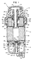
- Figure 1 is an elevational sectional view of a fuel filter assembly with a modular drain bowl in accordance with the present invention;
- Figure 2 is an enlarged top plan view of an anchoring means employed in the fuel filter assembly of Figure 1; and
- Figure 3 is a bottom plan view of the anchoring means of Figure 2.
- With reference to the drawings wherein like numerals represent like parts throughout the several figures, a fuel filter assembly incorporating a modular drain bowl in accordance with the present invention is generally designated by the
numeral 10.Fuel filter assembly 10 comprises abase 12, adisposable cartridge 14 and a modular drain bowl designated generally by thenumeral 16. The fuel filter assembly is especially adapted for incorporation into the fuel supply system of an internal combustion engine (not illustrated), such as a diesel engine, for removing particulate matter from the fuel and for separating water from the fuel. The separated water flows to the drain bowl for retention. The separated water is then selectively drained from the drain bowl as required. - According to the invention, the
base 12 is disposed generally above thefilter cartridge 14 which is locked to the base by means of aretainer collar 18, and thedrain bowl 16 is disposed below the filter cartridge. Thedrain bowl 16 has a modular construction which permits the drain bowl to be mounted and/or dismounted from the filter cartridge at the option of the vehicle operator, as will be detailed below. Thefilter cartridge 14 is specifically adapted to be fully functional with or without the associateddrain bowl 16. - The
base 12 and thedisposable cartridge 14 may assume a wide variety of configurations. For the disclosed embodiment, thebase 12 includes an inverted cup-like receptacle 20 which forms a skirt defining a lower receiving cavity for upper portions of the disposable cartridge. A central steppedaxial bore 22 on the base closely receives an elongated sleeve-like conduit 24 and an outer concentric sleeve-like conduit 26. The conduits provide generally coaxial fluid communication between the base and the disposable cartridge. An inlet connector (not illustrated) located at an upper side location of the base connects with the fuel line to provide fluid communication through the passageway defined by thefirst conduit 24. An outlet connector (not illustrated) also located at an upper side location of the base connects with the fuel line to provide remote fluid communication from the axial fluid passageway defined between the first andsecond conduits bracket 40, which may include a pair of openings for anchoring the filter base to the engine header, projects transversely at the rear of the base. - The
disposable filter cartridge 14 comprises a can-like container constructed from a pair of upper and lower cup-like sections circumferential roll seam 50. Theupper section 42 is dimensioned to be relatively closely received by thebase receptacle 20. Theupper section 42 includes a central axial opening. A sealinggrommet 46 mounted at the axial opening diametrally seals against theouter conduit 26. An integralannular lip 47 projects from the top surface of theupper section 42. - In a conventional fashion, a
secondary filter element 52, which has a continuous fan-shaped pleated configuration, is mounted in the upper section. The lower end of the secondary element is engaged by a multi-bentmedial plate 54 which has a central recess. Asecond sealing grommet 56 mounted at the recess diametrally seals thefirst conduit 24. A primary orfirst filter element 58, which also has a continuous fan-like configuration, engages the underside of the medial plate and is retained by alower plate 60. Thefirst filter element 58 is housed in thelower section 44. Asump 62 is formed at the bottom of the lower section to collect water which coalesces from the fuel. A centralaxial protrusion 64 of thelower section 44 includes anopening 65 which leads from thesump 62. - The
disposable cartridge 14 is retained to thebase 12 by means of theretainer collar 18. The collar includes an inwardly projectingannular shoulder 66 which engages theroll seam 50 of the cartridge for retentively locking the disposable cartridge to the base. The collar may threadably engage with the base or may include a pair ofspiral followers 68 which interact with ramps formed at the exterior of the base. For the disclosed embodiment, a positive locked position of the retainer collar is releasably retained by the spring force of aspring washer 69 with an inscribed star-like configuration. Leaves of the spring washer angularly alternate and are alternately biased so that the one set engages the base and the other set engages at the top of the disposable cartridge. A peripheral shoulder portion of the spring is also engageable against the upper protrudinglip 47 of the disposable cartridge. The spring bias provides a positive releasable locking engagement of catches of the followers to releasably lock the disposable cartridge to the base. - The disposable cartridge may also include a
volume plug 70 which is retained by anendcap 72 and includes acolumn 74 which extends axially in the first conduit. Theplug 70 functions to occupy a pre-established volume of the cartridge when the cartridge is mounted to the base so that upon dismounting of the cartridge for replacement, excess fuel which drains under the force of gravitation from the base will be retained in the cartridge and occupy the free volume gained by dismounting the cartridge. - The
modular drain bowl 16 is formed by a pair ofcooperative members first member 80 has an upper surface with a concave contour which closely mirrors the exterior surface of the lower end of the cartridge. The first member includes a centralaxial recess 84 which receives theaxial protrusion 64 of the sump opening of the cartridge. A radially peripheral portion of the first member forms a cylindrical skirt having aflange 86 which inwardly closely receives an upper end of the lower or second member. The lower orsecond member 82 forms a quasi-annular bowl which is centrally defined by a central slottedaxial column 90 formed by cooperative integral structures of themembers compressible seal ring 92 is disposed betweenopposed shoulders skirt flange 86 for fluidly sealing the first member with the second member. Asecond seal ring 98 seals the first member in fluid tight relationship against the outer surface of the cartridge along a sealing interface which surrounds theaxial protrusion 64 of the cartridge housing. Athird seal ring 101 is provided for fluidly sealing at the tapered outer portion forming a recessedshoulder 103 ofcentral bore 105 passing throughmember 82. Preferably, thesecond member 82 and optionallyfirst member 80 are formed of transparent materials, such as plastic, which allow for any water which is collected in the formed bowl to be readily visible for inspection from an exterior position. - A lower off-center portion of the
bowl member 82 has a threadedopening 97. A drain cock 99 is threaded to the opening to provide a valved drain passage so that collected water may be drained from the bowl as required. The drain cock 99 may have a conventional form and function such as a drain cock which is conventionally mounted to a filter cartridge for draining thecartridge sump 62. - With additional reference to Figures 2 and 3, the
modular bowl 16 is fastened to the cartridge through an anchoring means 100 which is disposed interiorly at the lower end of the cartridge housing adjacent the sump opening. The anchoring means 100 includes a contouredlower plug 102 having a lower reduced diameter and an upper enlarged diameter. The lower plug portion is exteriorly contoured for press fitting in theprotrusion 64 at the lower interior of the cartridge housing. The plug has anopening 104 which communicates with thesump opening 65. Three equiangularly spacedlegs 106 integrally extend from the plug at an oblique angle and integrally connect with aplatform 110. The platform has a central axial opening which is defined by a threadedsurface 112. Three angularly spacedapertures 114 are thus defined by the legs to provide communication through theplug opening 104 and thecartridge opening 65. - A head-
head bolt 120 is inserted through the axial cavity of the bowl members formed by the slottedcolumn 90. The head of the bolt engages the recessedshoulder 103 in the lower orsecond member 82. The shank of the bolt threads into the threadedsurface 112 of the platform for fastening the modular bowl to the cartridge. The bolt is tightened to axially load the seal rings 98 and 101 so that in conjunction withseal 92, the upper or first and lower or second members cooperate to seal the bowl in fluid tight relationship with the cartridge. - The
apertures 114 defined by the anchoring means function as an aspirated opening to facilitate the efficient passage of water collected in the cartridge sump. In addition, the anchoring means 100 can be employed for threadably receiving the drain cock 99 when the modular drain bowl is not desired. An anchoring means or molded member (not illustrated) similar to anchoring means 100 may also be located at the drain bowl opening for mounting the drain cock. - The filter assembly is modular in that the drain bowl may optionally be dismounted by unthreading the bolt from the anchoring means 100 and remounting the drain cock 99 at the cartridge opening by threadably engaging the drain cock into the anchoring means. The anchoring means in the latter configuration functions to provide an aspirated opening for fluid passage through the drain cock.
- While a preferred embodiment of the foregoing invention has been set forth for purposes of illustration, the foregoing description should not be deemed a limitation of the invention herein. Accordingly, various modifications, adaptations and alternatives may occur to one skilled in the art without departing from the present invention as defined in the appended claims.
Claims (16)
- A fuel filter assembly (10) of modular design having a base (12), a filter cartridge (14) mountable to the base (12) for filtering fuel, and a retainer (18) for retaining the filter cartridge (14) with the base (12), the base (12) having a fuel inlet, a fuel outlet, a first conduit (24) for interiorly defining a first axial passage, the first axial passage being in fluid communication with the inlet, a second conduit (26) for defining a second axial passage, the second axial passage being in fluid communication with the outlet, the filter cartridge (14) having first (58) and second (52) filter elements, a housing composed of first (44) and second (42) portions, the first portion (44) interiorly defining a sump (62), the first portion (44) comprising first opening means (65) for defining an opening for said sump (62), the second portion (42) comprising an end cap defining an axial opening for receiving the base first (24) and second (26) conduits, a first seal (46) for sealing the base second conduit (26) with the end cap, a medial plate (54) situated between said first (58) and second (52) filter elements defining an axial opening for receiving the base first conduit (24), a second seal (56) for sealing the base first conduit (24) with the medial plate (54), and defining a fuel path communicating with the base first axial passage, the base second axial passage and traversing the filter elements (58,52), characterized by:the filter cartridge (14) further comprising anchoring means (100) mounted interiorly adjacent the first portion (44) at a central position thereof for anchoring a fastener (120);bowl means (16) for forming a bowl for retaining fluid, said bowl means (16) being mountable to the filter cartridge (14) exteriorly adjacent the first portion (44), and comprising communication means (90) to provide fluid communication between said bowl and said first opening (65); anda fastener (120) engageable with said bowl means (16) and said anchoring means (100) for releasably fastening said bowl means (16) to the filter cartridge (14).
- The fuel filter assembly (10) of claim 1 characterized by said anchoring means (100) comprising a threaded surface (112) defining a second axial opening generally aligned with said first opening (65) and said fastener (120) comprising a threaded surface complementary with said anchoring means threaded surface (112).
- The fuel filter assembly of claim 2 characterized by said anchoring means (100) comprising a plug (102) press-fitted against said first portion (44) and a platform (110) axially spaced from said plug (102) and defining said second opening.
- The fuel filter assembly of claim 3 characterized by said anchoring means (100) further comprising passage means (104) for forming a passage extending between said sump (62) and said first opening (65).
- The fuel filter assembly of claim 3 and 4, characterized in that said anchoring means (100) further defines three angularly spaced apertures (114) generally symmetricallY disposed relative to said first opening (65).
- The fuel filter assembly of claims 1 to 5, characterized in that said fastener (120) comprises a bolt (120) and said bowl means (16) comprises a central axial cavity (105) and shoulder means (103) adjacent said cavity (105), said bolt (120) being inserted through said cavity (105) and engageable against said shoulder means (103).
- The fuel filter assembly of claims 1 to 6 characterized by said bowl means (16) comprising a first member (80) and a second member (82) which cooperate to form said bowl, said first member (80) having a generally concave surface which is generally complementary to the exterior surface of said first portion (44).
- The fuel filter assembly of claims 1 to 7 characterized by said bowl means (16) further defining a drain passage (97) and further comprising valve means (99) disposed in said passage (97) for selectively opening and closing said drain passage (97).
- The fuel filter assembly of claims 1 to 8 characterized by seal means (98) engageable between the filter cartridge (14) and said bowl means (16) and axially loadable for providing a fluid tight seal between the filter cartridge (14) and said bowl means (16).
- The fuel filter assembly of claims 1 to 9 characterized in that at least a portion of said bowl means (16) is constructed from transparent material.
- The fuel filter assembly of claim 3 characterized in that a plurality of angularly spaced legs (106) integrally connect said plug (102) and said platform (110) and at least partially define a plurality of apertures (114).
- The fuel filter assembly of claim 2 characterized by said bowl means (16) comprising a pair of sections (80,82) which are axially forced together when said fastener means (120) engages said threaded surface (112)·
- The fuel filter assembly of claims 1 to 10 characterized by the first portion (44) comprising a convex exterior surface, said exterior surface including a central axially protruding portion (64) surrounding said first opening means (65).
- A modular bowl assembly having a second member (82) having an upper side portion and a lower portion which forms a drain bowl and an outlet (97) for draining the bowl, characterized by:a first member (80) comprising a concave exterior surface and defining a radially peripheral skirt, said first member (80) defining a central axial recess (84) for receiving a fastener (120);the second member upper side portion engaging said first member skirt; andsealing means (92) for sealing the second member (82) with said first member (80) to form a fluid-tight enclosure.
- The modular bowl assembly of claim 14 characterized in that said members (80,82) each have an annular shoulder (94,96) and said sealing means (92) comprises a seal ring (92) which compressively engages said annular shoulders (94,96).
- The modular bowl assembly of claim 14 characterized by said second member (82) including a shoulder extending transversely adjacent said axial recess.
Applications Claiming Priority (2)
| Application Number | Priority Date | Filing Date | Title |
|---|---|---|---|
| US748775 | 1991-08-22 | ||
| US07/748,775 US5236579A (en) | 1991-08-22 | 1991-08-22 | Fuel filter assembly with modular drain bowl |
Publications (2)
| Publication Number | Publication Date |
|---|---|
| EP0529286A1 EP0529286A1 (en) | 1993-03-03 |
| EP0529286B1 true EP0529286B1 (en) | 1996-11-20 |
Family
ID=25010874
Family Applications (1)
| Application Number | Title | Priority Date | Filing Date |
|---|---|---|---|
| EP92112283A Expired - Lifetime EP0529286B1 (en) | 1991-08-22 | 1992-07-17 | Fuel filter assembly with modular drain bowl and modular bowl assembly |
Country Status (5)
| Country | Link |
|---|---|
| US (1) | US5236579A (en) |
| EP (1) | EP0529286B1 (en) |
| JP (1) | JP3358739B2 (en) |
| DE (1) | DE69215288T2 (en) |
| ES (1) | ES2095361T3 (en) |
Cited By (1)
| Publication number | Priority date | Publication date | Assignee | Title |
|---|---|---|---|---|
| DE202008006721U1 (en) * | 2008-05-16 | 2009-09-24 | Mann+Hummel Gmbh | filter |
Families Citing this family (47)
| Publication number | Priority date | Publication date | Assignee | Title |
|---|---|---|---|---|
| US5186829A (en) * | 1991-08-16 | 1993-02-16 | Stanadyne Automotive Corp. | Fuel filter key system |
| DE4344586A1 (en) * | 1993-12-24 | 1995-06-29 | Knecht Filterwerke Gmbh | Diesel fuel filter |
| US5547565A (en) * | 1994-12-05 | 1996-08-20 | Baldwin Filters, Inc. | Fuel/water separator with adaptor plate for drain valve and water detector |
| GB9504486D0 (en) * | 1995-03-07 | 1995-04-26 | Lucas Ind Plc | Fluid treatment apparatus |
| US5817234A (en) * | 1995-04-13 | 1998-10-06 | Advanced Performance Technology, Inc. | Fluid filter and method for assembling same |
| US5667678A (en) * | 1995-04-13 | 1997-09-16 | Advanced Performance Technology, Inc. | Plastic fluid filter and method for assembling same |
| US5915926A (en) * | 1996-04-19 | 1999-06-29 | Stanadyne Automotive Corp. | Lift pump for filter module |
| US5985144A (en) * | 1997-07-03 | 1999-11-16 | Stanadyne Automotive Corp. | Reverse flow cartridge |
| DE19943240A1 (en) * | 1999-09-10 | 2001-03-15 | Mann & Hummel Filter | Fuel filter in a suspended installation has a pot of transparent plastics to catch separated water with an O-ring seal between the pot and the filter housing in an inexpensive and robust assembly |
| US6471071B1 (en) * | 2000-05-09 | 2002-10-29 | Honeywell International, Inc. | Universal grommet seal for spin-on type filters |
| US20110203985A1 (en) * | 2009-08-21 | 2011-08-25 | Omnipure Filter Company, Pllc | Keyed system for connection of filter to filter holder |
| US7476314B2 (en) * | 2000-08-11 | 2009-01-13 | Reid Roger P | Keyed system for connection of filter cartridge to filter holder |
| US9314722B2 (en) | 2000-08-11 | 2016-04-19 | Omnipure Filter Company, Inc. | Keyed system for connection of filter cartridge to filter holder |
| US6695891B2 (en) * | 2000-08-11 | 2004-02-24 | Roger P. Reid | Keyed system for connection of filter cartridge to filter holder |
| DE10220662B4 (en) * | 2002-05-10 | 2005-08-11 | Hydraulik-Ring Gmbh | Filter cartridge for liquid, freeze-risk media, in particular for use in fuel cell vehicles and internal combustion engines, preferably diesel engines |
| US7232521B2 (en) * | 2002-06-07 | 2007-06-19 | Baldwin Filters, Inc. | Environmentally friendly acid neutralizing cartridge |
| GB2389806B (en) * | 2002-06-07 | 2005-10-26 | Baldwin Filters Inc | Housing for environmentally friendly filter cartridge |
| US7014761B2 (en) * | 2002-06-07 | 2006-03-21 | Baldwin Filters, Inc. | Environmentally friendly dual lube venturi filter cartridge |
| GB2390556B (en) * | 2002-06-07 | 2005-10-26 | Baldwin Filters Inc | Environmentally friendly acid neutralizing full flow cartridge |
| US7168573B2 (en) * | 2002-06-07 | 2007-01-30 | Baldwin Filters, Inc. | Environmentally friendly filter cartridge |
| US6793818B1 (en) | 2002-06-19 | 2004-09-21 | Brunswick Corporation | Support and locking structure for a fuel filter |
| CA2394514A1 (en) * | 2002-07-23 | 2004-01-23 | Cognos Incorporated | Method and system for parameterized database drill-through |
| US6969458B1 (en) | 2003-07-23 | 2005-11-29 | Wix Filtration Corp. | Filter |
| EP1718388A4 (en) * | 2004-02-17 | 2007-05-23 | Stanadyne Corp | Drain valve insert |
| DE102004025062B4 (en) * | 2004-05-18 | 2006-09-14 | Hydraulik-Ring Gmbh | Freezer-compatible metering valve |
| WO2006023748A2 (en) * | 2004-08-20 | 2006-03-02 | Stanadyne Corporation | Reverse flow fuel filter |
| US20070062860A1 (en) * | 2005-09-16 | 2007-03-22 | Mcdowell Ronald A | Fluid control device |
| US20070084776A1 (en) * | 2005-09-30 | 2007-04-19 | Sasur Timothy M | Water separation and filtration structure |
| US20070114170A1 (en) * | 2005-11-18 | 2007-05-24 | Baldwin Filters, Inc. | Fuel filter cartridge apparatus |
| DE102006024013B4 (en) * | 2006-05-23 | 2008-10-09 | Hydac Filtertechnik Gmbh | Method and device for separating and removing water contained in liquid fuels, in particular water from diesel oil |
| DE102007004687B4 (en) | 2007-01-25 | 2012-03-01 | Hydraulik-Ring Gmbh | Volume quantity dispensing unit and method for calibrating the pressure output signal volume quantity characteristic |
| US8147691B2 (en) * | 2007-09-21 | 2012-04-03 | Baldwin Filters, Inc. | Filter cartridge housing attachment systems |
| US8496821B2 (en) * | 2007-12-28 | 2013-07-30 | Caterpillar Inc. | Systems and methods for filtering fuel |
| DE102008012780B4 (en) | 2008-03-05 | 2012-10-04 | Hydraulik-Ring Gmbh | exhaust treatment device |
| US20110017649A1 (en) * | 2009-07-24 | 2011-01-27 | Sasur Timothy M | Two stage filter cartridge |
| DE102009035940C5 (en) * | 2009-08-03 | 2017-04-20 | Cummins Ltd. | SCR exhaust treatment device |
| WO2011102934A1 (en) | 2010-01-22 | 2011-08-25 | Donaldson Company, Inc. | Pulse jet air cleaner systems; evacution valve arrangements; air cleaner components; and, methods |
| USD712007S1 (en) | 2010-03-03 | 2014-08-26 | Omnipure Filter Company, Inc. | Filter for liquid |
| DE102010061222B4 (en) | 2010-12-14 | 2015-05-07 | Cummins Ltd. | SCR exhaust treatment device |
| JP2014108387A (en) * | 2012-12-01 | 2014-06-12 | Nippon Rokaki Kk | Filter |
| WO2014110354A2 (en) | 2013-01-14 | 2014-07-17 | Cummins Filtration Ip, Inc. | Cleanable filter |
| JP6232707B2 (en) * | 2013-02-11 | 2017-11-22 | 京三電機株式会社 | Moisture collector and fuel filter device including the same |
| DE102015003162A1 (en) * | 2015-03-13 | 2016-09-15 | Mann + Hummel Gmbh | Fuel filter element with a front and a main filter element and fuel filter |
| BR112019006701B1 (en) | 2016-10-03 | 2022-11-01 | Parker-Hannifin Corporation | FILTER CARTRIDGE, FILTER ELEMENT ASSEMBLY AND HEAD ASSEMBLY |
| WO2018075058A1 (en) | 2016-10-21 | 2018-04-26 | Cummins Filtration Ip, Inc. | Bowl for filter assemblies |
| US20180161708A1 (en) * | 2016-12-12 | 2018-06-14 | Caterpillar Inc. | Fluid filter system |
| CN110769913B (en) | 2017-05-31 | 2021-11-16 | 帕克-汉尼芬公司 | Filter element with twist lock and/or sliding piston, assembly and method |
Family Cites Families (6)
| Publication number | Priority date | Publication date | Assignee | Title |
|---|---|---|---|---|
| US3105042A (en) * | 1960-10-18 | 1963-09-24 | Vernon D Roosa | Filter assembly |
| CA1190865A (en) * | 1982-02-24 | 1985-07-23 | Michael E. Wilson | Filter assembly |
| FR2564147A1 (en) * | 1984-05-09 | 1985-11-15 | Mielle Jean Pierre | Device for unwaxing, liquifying and purifying diesel fuel in diesel engines |
| US4619764A (en) * | 1984-06-19 | 1986-10-28 | Parker-Hannifin Corporation | Repelling-action filter unit and assembly |
| FR2621959A1 (en) * | 1987-10-19 | 1989-04-21 | Grand Jean | Modular system for heating, filtering and decanting fuel, particularly diesel fuel |
| US5017285A (en) * | 1989-06-28 | 1991-05-21 | Stanadyne Automotive Corp. | Fuel filter and cartridge assembly |
-
1991
- 1991-08-22 US US07/748,775 patent/US5236579A/en not_active Expired - Lifetime
-
1992
- 1992-07-17 EP EP92112283A patent/EP0529286B1/en not_active Expired - Lifetime
- 1992-07-17 DE DE69215288T patent/DE69215288T2/en not_active Expired - Fee Related
- 1992-07-17 ES ES92112283T patent/ES2095361T3/en not_active Expired - Lifetime
- 1992-08-21 JP JP24557692A patent/JP3358739B2/en not_active Expired - Lifetime
Cited By (2)
| Publication number | Priority date | Publication date | Assignee | Title |
|---|---|---|---|---|
| DE202008006721U1 (en) * | 2008-05-16 | 2009-09-24 | Mann+Hummel Gmbh | filter |
| US8163178B2 (en) | 2008-05-16 | 2012-04-24 | Mann+Hummel Gmbh | Filter |
Also Published As
| Publication number | Publication date |
|---|---|
| US5236579A (en) | 1993-08-17 |
| ES2095361T3 (en) | 1997-02-16 |
| JP3358739B2 (en) | 2002-12-24 |
| DE69215288D1 (en) | 1997-01-02 |
| DE69215288T2 (en) | 1997-05-28 |
| EP0529286A1 (en) | 1993-03-03 |
| JPH05261213A (en) | 1993-10-12 |
Similar Documents
| Publication | Publication Date | Title |
|---|---|---|
| EP0529286B1 (en) | Fuel filter assembly with modular drain bowl and modular bowl assembly | |
| US5312546A (en) | Dry change fuel filter system | |
| US5203994A (en) | Fuel filter retention system | |
| US5302284A (en) | Fuel filter with spring-loaded retention system | |
| AU719225B2 (en) | Self-evacuating water-separating fuel filter | |
| JP3119484B2 (en) | Fuel filter | |
| EP0405447B1 (en) | Fuel filter | |
| US6068762A (en) | Reusable oil filter assembly | |
| US5858227A (en) | Fuel filter assembly with in-line valve | |
| US5413711A (en) | Fuel filter with internal vent | |
| US4976852A (en) | Fuel filter | |
| CA2085674C (en) | Filter for fuels or lubricants of an internal combustion engine | |
| EP1311334B1 (en) | Fluid filter operatable only with installed filter element | |
| US5670042A (en) | Fuel filter assembly with replaceable element having integral cover | |
| JPH0450844B2 (en) | ||
| US6364121B1 (en) | Filter cartridge with grommet spring | |
| MXPA02003228A (en) | Dual pass fuel filter assembly and element therefor. | |
| US20070034560A1 (en) | Drain valve alignment system for filter assembly | |
| US20210129056A1 (en) | Filter cartridge locking assembly |
Legal Events
| Date | Code | Title | Description |
|---|---|---|---|
| PUAI | Public reference made under article 153(3) epc to a published international application that has entered the european phase |
Free format text: ORIGINAL CODE: 0009012 |
|
| AK | Designated contracting states |
Kind code of ref document: A1 Designated state(s): DE ES FR GB IT |
|
| 17P | Request for examination filed |
Effective date: 19930831 |
|
| 17Q | First examination report despatched |
Effective date: 19940603 |
|
| GRAG | Despatch of communication of intention to grant |
Free format text: ORIGINAL CODE: EPIDOS AGRA |
|
| GRAH | Despatch of communication of intention to grant a patent |
Free format text: ORIGINAL CODE: EPIDOS IGRA |
|
| GRAH | Despatch of communication of intention to grant a patent |
Free format text: ORIGINAL CODE: EPIDOS IGRA |
|
| GRAA | (expected) grant |
Free format text: ORIGINAL CODE: 0009210 |
|
| AK | Designated contracting states |
Kind code of ref document: B1 Designated state(s): DE ES FR GB IT |
|
| REF | Corresponds to: |
Ref document number: 69215288 Country of ref document: DE Date of ref document: 19970102 |
|
| ITF | It: translation for a ep patent filed |
Owner name: 0403;43FIFUFFICIO TECNICO ING. A. MANNUC |
|
| ET | Fr: translation filed | ||
| REG | Reference to a national code |
Ref country code: ES Ref legal event code: FG2A Ref document number: 2095361 Country of ref document: ES Kind code of ref document: T3 |
|
| PLBE | No opposition filed within time limit |
Free format text: ORIGINAL CODE: 0009261 |
|
| STAA | Information on the status of an ep patent application or granted ep patent |
Free format text: STATUS: NO OPPOSITION FILED WITHIN TIME LIMIT |
|
| 26N | No opposition filed | ||
| REG | Reference to a national code |
Ref country code: GB Ref legal event code: IF02 |
|
| PGFP | Annual fee paid to national office [announced via postgrant information from national office to epo] |
Ref country code: ES Payment date: 20080728 Year of fee payment: 17 Ref country code: DE Payment date: 20080829 Year of fee payment: 17 |
|
| PGFP | Annual fee paid to national office [announced via postgrant information from national office to epo] |
Ref country code: IT Payment date: 20080728 Year of fee payment: 17 Ref country code: FR Payment date: 20080729 Year of fee payment: 17 |
|
| PGFP | Annual fee paid to national office [announced via postgrant information from national office to epo] |
Ref country code: GB Payment date: 20080729 Year of fee payment: 17 |
|
| GBPC | Gb: european patent ceased through non-payment of renewal fee |
Effective date: 20090717 |
|
| REG | Reference to a national code |
Ref country code: FR Ref legal event code: ST Effective date: 20100331 |
|
| PG25 | Lapsed in a contracting state [announced via postgrant information from national office to epo] |
Ref country code: FR Free format text: LAPSE BECAUSE OF NON-PAYMENT OF DUE FEES Effective date: 20090731 |
|
| PG25 | Lapsed in a contracting state [announced via postgrant information from national office to epo] |
Ref country code: GB Free format text: LAPSE BECAUSE OF NON-PAYMENT OF DUE FEES Effective date: 20090717 |
|
| PG25 | Lapsed in a contracting state [announced via postgrant information from national office to epo] |
Ref country code: DE Free format text: LAPSE BECAUSE OF NON-PAYMENT OF DUE FEES Effective date: 20100202 |
|
| REG | Reference to a national code |
Ref country code: ES Ref legal event code: FD2A Effective date: 20090718 |
|
| PG25 | Lapsed in a contracting state [announced via postgrant information from national office to epo] |
Ref country code: ES Free format text: LAPSE BECAUSE OF NON-PAYMENT OF DUE FEES Effective date: 20090718 |
|
| PG25 | Lapsed in a contracting state [announced via postgrant information from national office to epo] |
Ref country code: IT Free format text: LAPSE BECAUSE OF NON-PAYMENT OF DUE FEES Effective date: 20090717 |