EP0529098B1 - Color cathode-ray tube - Google Patents
Color cathode-ray tube Download PDFInfo
- Publication number
- EP0529098B1 EP0529098B1 EP92906681A EP92906681A EP0529098B1 EP 0529098 B1 EP0529098 B1 EP 0529098B1 EP 92906681 A EP92906681 A EP 92906681A EP 92906681 A EP92906681 A EP 92906681A EP 0529098 B1 EP0529098 B1 EP 0529098B1
- Authority
- EP
- European Patent Office
- Prior art keywords
- phosphor
- rare earth
- europium
- red
- earth element
- Prior art date
- Legal status (The legal status is an assumption and is not a legal conclusion. Google has not performed a legal analysis and makes no representation as to the accuracy of the status listed.)
- Expired - Lifetime
Links
- OAICVXFJPJFONN-UHFFFAOYSA-N Phosphorus Chemical compound [P] OAICVXFJPJFONN-UHFFFAOYSA-N 0.000 claims abstract description 155
- 229910052693 Europium Inorganic materials 0.000 claims abstract description 34
- OGPBJKLSAFTDLK-UHFFFAOYSA-N europium atom Chemical compound [Eu] OGPBJKLSAFTDLK-UHFFFAOYSA-N 0.000 claims abstract description 27
- 229910052761 rare earth metal Inorganic materials 0.000 claims abstract description 27
- 239000011248 coating agent Substances 0.000 claims abstract description 7
- 238000000576 coating method Methods 0.000 claims abstract description 4
- 229910001404 rare earth metal oxide Inorganic materials 0.000 claims abstract description 4
- 239000000203 mixture Substances 0.000 claims description 62
- 238000002156 mixing Methods 0.000 claims description 14
- 239000001054 red pigment Substances 0.000 claims description 14
- UQSXHKLRYXJYBZ-UHFFFAOYSA-N Iron oxide Chemical group [Fe]=O UQSXHKLRYXJYBZ-UHFFFAOYSA-N 0.000 claims description 12
- UAHZTKVCYHJBJQ-UHFFFAOYSA-N [P].S=O Chemical compound [P].S=O UAHZTKVCYHJBJQ-UHFFFAOYSA-N 0.000 claims description 10
- 239000003795 chemical substances by application Substances 0.000 claims description 10
- -1 europium activated yttrium oxysulfide phosphor Chemical class 0.000 claims description 10
- 239000003086 colorant Substances 0.000 claims description 5
- 238000007581 slurry coating method Methods 0.000 claims description 5
- 239000004925 Acrylic resin Substances 0.000 claims description 3
- 229920000178 Acrylic resin Polymers 0.000 claims description 3
- XUIMIQQOPSSXEZ-UHFFFAOYSA-N Silicon Chemical group [Si] XUIMIQQOPSSXEZ-UHFFFAOYSA-N 0.000 claims description 2
- 239000002174 Styrene-butadiene Substances 0.000 claims description 2
- MTAZNLWOLGHBHU-UHFFFAOYSA-N butadiene-styrene rubber Chemical compound C=CC=C.C=CC1=CC=CC=C1 MTAZNLWOLGHBHU-UHFFFAOYSA-N 0.000 claims description 2
- 239000011347 resin Substances 0.000 claims description 2
- 229920005989 resin Polymers 0.000 claims description 2
- 229910052710 silicon Inorganic materials 0.000 claims description 2
- 239000010703 silicon Substances 0.000 claims description 2
- 239000011115 styrene butadiene Substances 0.000 claims description 2
- 229920003048 styrene butadiene rubber Polymers 0.000 claims description 2
- XLOMVQKBTHCTTD-UHFFFAOYSA-N zinc oxide Inorganic materials [Zn]=O XLOMVQKBTHCTTD-UHFFFAOYSA-N 0.000 claims 1
- 239000011787 zinc oxide Substances 0.000 claims 1
- MCSXGCZMEPXKIW-UHFFFAOYSA-N 3-hydroxy-4-[(4-methyl-2-nitrophenyl)diazenyl]-N-(3-nitrophenyl)naphthalene-2-carboxamide Chemical compound Cc1ccc(N=Nc2c(O)c(cc3ccccc23)C(=O)Nc2cccc(c2)[N+]([O-])=O)c(c1)[N+]([O-])=O MCSXGCZMEPXKIW-UHFFFAOYSA-N 0.000 abstract 1
- UCKMPCXJQFINFW-UHFFFAOYSA-N Sulphide Chemical compound [S-2] UCKMPCXJQFINFW-UHFFFAOYSA-N 0.000 abstract 1
- 150000002910 rare earth metals Chemical class 0.000 abstract 1
- RUDFQVOCFDJEEF-UHFFFAOYSA-N oxygen(2-);yttrium(3+) Chemical class [O-2].[O-2].[O-2].[Y+3].[Y+3] RUDFQVOCFDJEEF-UHFFFAOYSA-N 0.000 description 35
- 239000002002 slurry Substances 0.000 description 26
- 239000012190 activator Substances 0.000 description 17
- QTBSBXVTEAMEQO-UHFFFAOYSA-N Acetic acid Chemical compound CC(O)=O QTBSBXVTEAMEQO-UHFFFAOYSA-N 0.000 description 15
- XLYOFNOQVPJJNP-UHFFFAOYSA-N water Substances O XLYOFNOQVPJJNP-UHFFFAOYSA-N 0.000 description 11
- VYPSYNLAJGMNEJ-UHFFFAOYSA-N Silicium dioxide Chemical compound O=[Si]=O VYPSYNLAJGMNEJ-UHFFFAOYSA-N 0.000 description 10
- 230000008859 change Effects 0.000 description 7
- 238000000034 method Methods 0.000 description 7
- JEIPFZHSYJVQDO-UHFFFAOYSA-N iron(III) oxide Inorganic materials O=[Fe]O[Fe]=O JEIPFZHSYJVQDO-UHFFFAOYSA-N 0.000 description 6
- 239000007788 liquid Substances 0.000 description 6
- 239000002253 acid Substances 0.000 description 5
- 238000013019 agitation Methods 0.000 description 5
- 239000000470 constituent Substances 0.000 description 5
- 238000010908 decantation Methods 0.000 description 5
- 239000006228 supernatant Substances 0.000 description 5
- 229910052771 Terbium Inorganic materials 0.000 description 4
- 239000000049 pigment Substances 0.000 description 4
- 230000000630 rising effect Effects 0.000 description 4
- 239000000377 silicon dioxide Substances 0.000 description 4
- 239000000725 suspension Substances 0.000 description 4
- RLQWHDODQVOVKU-UHFFFAOYSA-N tetrapotassium;silicate Chemical compound [K+].[K+].[K+].[K+].[O-][Si]([O-])([O-])[O-] RLQWHDODQVOVKU-UHFFFAOYSA-N 0.000 description 4
- VEXZGXHMUGYJMC-UHFFFAOYSA-N Hydrochloric acid Chemical compound Cl VEXZGXHMUGYJMC-UHFFFAOYSA-N 0.000 description 3
- MUBZPKHOEPUJKR-UHFFFAOYSA-N Oxalic acid Chemical compound OC(=O)C(O)=O MUBZPKHOEPUJKR-UHFFFAOYSA-N 0.000 description 3
- 229910052772 Samarium Inorganic materials 0.000 description 3
- HEMHJVSKTPXQMS-UHFFFAOYSA-M Sodium hydroxide Chemical compound [OH-].[Na+] HEMHJVSKTPXQMS-UHFFFAOYSA-M 0.000 description 3
- 229910052681 coesite Inorganic materials 0.000 description 3
- 229910052906 cristobalite Inorganic materials 0.000 description 3
- 230000000694 effects Effects 0.000 description 3
- 229910052747 lanthanoid Inorganic materials 0.000 description 3
- 150000002602 lanthanoids Chemical class 0.000 description 3
- 229910052709 silver Inorganic materials 0.000 description 3
- 229910052682 stishovite Inorganic materials 0.000 description 3
- 229910052905 tridymite Inorganic materials 0.000 description 3
- 229910052727 yttrium Inorganic materials 0.000 description 3
- 229910052725 zinc Inorganic materials 0.000 description 3
- 239000011701 zinc Substances 0.000 description 3
- 108010010803 Gelatin Proteins 0.000 description 2
- 229920000084 Gum arabic Polymers 0.000 description 2
- 241000978776 Senegalia senegal Species 0.000 description 2
- 235000010489 acacia gum Nutrition 0.000 description 2
- 239000000205 acacia gum Substances 0.000 description 2
- 239000007864 aqueous solution Substances 0.000 description 2
- 238000005354 coacervation Methods 0.000 description 2
- 239000006255 coating slurry Substances 0.000 description 2
- 239000008119 colloidal silica Substances 0.000 description 2
- 229910052802 copper Inorganic materials 0.000 description 2
- 229920000159 gelatin Polymers 0.000 description 2
- 239000008273 gelatin Substances 0.000 description 2
- 235000019322 gelatine Nutrition 0.000 description 2
- 235000011852 gelatine desserts Nutrition 0.000 description 2
- YBMRDBCBODYGJE-UHFFFAOYSA-N germanium dioxide Chemical compound O=[Ge]=O YBMRDBCBODYGJE-UHFFFAOYSA-N 0.000 description 2
- 239000011572 manganese Substances 0.000 description 2
- 238000004519 manufacturing process Methods 0.000 description 2
- 229910001388 sodium aluminate Inorganic materials 0.000 description 2
- 238000003756 stirring Methods 0.000 description 2
- 239000000126 substance Substances 0.000 description 2
- XTQHKBHJIVJGKJ-UHFFFAOYSA-N sulfur monoxide Chemical compound S=O XTQHKBHJIVJGKJ-UHFFFAOYSA-N 0.000 description 2
- 238000005406 washing Methods 0.000 description 2
- NWONKYPBYAMBJT-UHFFFAOYSA-L zinc sulfate Chemical compound [Zn+2].[O-]S([O-])(=O)=O NWONKYPBYAMBJT-UHFFFAOYSA-L 0.000 description 2
- 229910000368 zinc sulfate Inorganic materials 0.000 description 2
- 229910052692 Dysprosium Inorganic materials 0.000 description 1
- 229910052779 Neodymium Inorganic materials 0.000 description 1
- 229910052777 Praseodymium Inorganic materials 0.000 description 1
- 239000003929 acidic solution Substances 0.000 description 1
- NIXOWILDQLNWCW-UHFFFAOYSA-N acrylic acid group Chemical group C(C=C)(=O)O NIXOWILDQLNWCW-UHFFFAOYSA-N 0.000 description 1
- 230000002776 aggregation Effects 0.000 description 1
- 238000004220 aggregation Methods 0.000 description 1
- ANBBXQWFNXMHLD-UHFFFAOYSA-N aluminum;sodium;oxygen(2-) Chemical compound [O-2].[O-2].[Na+].[Al+3] ANBBXQWFNXMHLD-UHFFFAOYSA-N 0.000 description 1
- 230000015572 biosynthetic process Effects 0.000 description 1
- 238000001035 drying Methods 0.000 description 1
- 238000010410 dusting Methods 0.000 description 1
- 238000010894 electron beam technology Methods 0.000 description 1
- 239000000839 emulsion Substances 0.000 description 1
- 229910001940 europium oxide Inorganic materials 0.000 description 1
- AEBZCFFCDTZXHP-UHFFFAOYSA-N europium(3+);oxygen(2-) Chemical compound [O-2].[O-2].[O-2].[Eu+3].[Eu+3] AEBZCFFCDTZXHP-UHFFFAOYSA-N 0.000 description 1
- 230000001747 exhibiting effect Effects 0.000 description 1
- 238000001914 filtration Methods 0.000 description 1
- 230000004907 flux Effects 0.000 description 1
- XLYOFNOQVPJJNP-UHFFFAOYSA-M hydroxide Chemical compound [OH-] XLYOFNOQVPJJNP-UHFFFAOYSA-M 0.000 description 1
- 230000006872 improvement Effects 0.000 description 1
- 239000003112 inhibitor Substances 0.000 description 1
- 229910052746 lanthanum Inorganic materials 0.000 description 1
- 230000031700 light absorption Effects 0.000 description 1
- 229910052748 manganese Inorganic materials 0.000 description 1
- 239000000463 material Substances 0.000 description 1
- 238000005259 measurement Methods 0.000 description 1
- 239000012528 membrane Substances 0.000 description 1
- QEFYFXOXNSNQGX-UHFFFAOYSA-N neodymium atom Chemical compound [Nd] QEFYFXOXNSNQGX-UHFFFAOYSA-N 0.000 description 1
- 150000002894 organic compounds Chemical class 0.000 description 1
- 150000003891 oxalate salts Chemical class 0.000 description 1
- 235000006408 oxalic acid Nutrition 0.000 description 1
- SIWVEOZUMHYXCS-UHFFFAOYSA-N oxo(oxoyttriooxy)yttrium Chemical compound O=[Y]O[Y]=O SIWVEOZUMHYXCS-UHFFFAOYSA-N 0.000 description 1
- 239000004332 silver Substances 0.000 description 1
- 235000011121 sodium hydroxide Nutrition 0.000 description 1
- GKCNVZWZCYIBPR-UHFFFAOYSA-N sulfanylideneindium Chemical compound [In]=S GKCNVZWZCYIBPR-UHFFFAOYSA-N 0.000 description 1
- 238000004381 surface treatment Methods 0.000 description 1
- 238000002834 transmittance Methods 0.000 description 1
- LSGOVYNHVSXFFJ-UHFFFAOYSA-N vanadate(3-) Chemical compound [O-][V]([O-])([O-])=O LSGOVYNHVSXFFJ-UHFFFAOYSA-N 0.000 description 1
- 229910052844 willemite Inorganic materials 0.000 description 1
- DEXZEPDUSNRVTN-UHFFFAOYSA-K yttrium(3+);trihydroxide Chemical compound [OH-].[OH-].[OH-].[Y+3] DEXZEPDUSNRVTN-UHFFFAOYSA-K 0.000 description 1
- 229960001763 zinc sulfate Drugs 0.000 description 1
- 239000011686 zinc sulphate Substances 0.000 description 1
Images


Classifications
-
- C—CHEMISTRY; METALLURGY
- C09—DYES; PAINTS; POLISHES; NATURAL RESINS; ADHESIVES; COMPOSITIONS NOT OTHERWISE PROVIDED FOR; APPLICATIONS OF MATERIALS NOT OTHERWISE PROVIDED FOR
- C09K—MATERIALS FOR MISCELLANEOUS APPLICATIONS, NOT PROVIDED FOR ELSEWHERE
- C09K11/00—Luminescent, e.g. electroluminescent, chemiluminescent materials
- C09K11/08—Luminescent, e.g. electroluminescent, chemiluminescent materials containing inorganic luminescent materials
- C09K11/77—Luminescent, e.g. electroluminescent, chemiluminescent materials containing inorganic luminescent materials containing rare earth metals
- C09K11/7783—Luminescent, e.g. electroluminescent, chemiluminescent materials containing inorganic luminescent materials containing rare earth metals containing two or more rare earth metals one of which being europium
- C09K11/7784—Chalcogenides
- C09K11/7787—Oxides
- C09K11/7789—Oxysulfides
-
- C—CHEMISTRY; METALLURGY
- C09—DYES; PAINTS; POLISHES; NATURAL RESINS; ADHESIVES; COMPOSITIONS NOT OTHERWISE PROVIDED FOR; APPLICATIONS OF MATERIALS NOT OTHERWISE PROVIDED FOR
- C09K—MATERIALS FOR MISCELLANEOUS APPLICATIONS, NOT PROVIDED FOR ELSEWHERE
- C09K11/00—Luminescent, e.g. electroluminescent, chemiluminescent materials
- C09K11/08—Luminescent, e.g. electroluminescent, chemiluminescent materials containing inorganic luminescent materials
-
- C—CHEMISTRY; METALLURGY
- C09—DYES; PAINTS; POLISHES; NATURAL RESINS; ADHESIVES; COMPOSITIONS NOT OTHERWISE PROVIDED FOR; APPLICATIONS OF MATERIALS NOT OTHERWISE PROVIDED FOR
- C09K—MATERIALS FOR MISCELLANEOUS APPLICATIONS, NOT PROVIDED FOR ELSEWHERE
- C09K11/00—Luminescent, e.g. electroluminescent, chemiluminescent materials
- C09K11/02—Use of particular materials as binders, particle coatings or suspension media therefor
- C09K11/025—Use of particular materials as binders, particle coatings or suspension media therefor non-luminescent particle coatings or suspension media
-
- C—CHEMISTRY; METALLURGY
- C09—DYES; PAINTS; POLISHES; NATURAL RESINS; ADHESIVES; COMPOSITIONS NOT OTHERWISE PROVIDED FOR; APPLICATIONS OF MATERIALS NOT OTHERWISE PROVIDED FOR
- C09K—MATERIALS FOR MISCELLANEOUS APPLICATIONS, NOT PROVIDED FOR ELSEWHERE
- C09K11/00—Luminescent, e.g. electroluminescent, chemiluminescent materials
- C09K11/08—Luminescent, e.g. electroluminescent, chemiluminescent materials containing inorganic luminescent materials
- C09K11/77—Luminescent, e.g. electroluminescent, chemiluminescent materials containing inorganic luminescent materials containing rare earth metals
- C09K11/7783—Luminescent, e.g. electroluminescent, chemiluminescent materials containing inorganic luminescent materials containing rare earth metals containing two or more rare earth metals one of which being europium
- C09K11/7784—Chalcogenides
- C09K11/7787—Oxides
-
- H—ELECTRICITY
- H01—ELECTRIC ELEMENTS
- H01J—ELECTRIC DISCHARGE TUBES OR DISCHARGE LAMPS
- H01J29/00—Details of cathode-ray tubes or of electron-beam tubes of the types covered by group H01J31/00
- H01J29/02—Electrodes; Screens; Mounting, supporting, spacing or insulating thereof
- H01J29/10—Screens on or from which an image or pattern is formed, picked up, converted or stored
- H01J29/18—Luminescent screens
- H01J29/20—Luminescent screens characterised by the luminescent material
-
- H—ELECTRICITY
- H01—ELECTRIC ELEMENTS
- H01J—ELECTRIC DISCHARGE TUBES OR DISCHARGE LAMPS
- H01J29/00—Details of cathode-ray tubes or of electron-beam tubes of the types covered by group H01J31/00
- H01J29/02—Electrodes; Screens; Mounting, supporting, spacing or insulating thereof
- H01J29/10—Screens on or from which an image or pattern is formed, picked up, converted or stored
- H01J29/18—Luminescent screens
- H01J29/30—Luminescent screens with luminescent material discontinuously arranged, e.g. in dots, in lines
- H01J29/32—Luminescent screens with luminescent material discontinuously arranged, e.g. in dots, in lines with adjacent dots or lines of different luminescent material, e.g. for colour television
Definitions
- This invention relates to a color picture tube having a red emission composition comprising a combination of phosphors having specified emission colors on the fluorescent screen.
- europium activated rare earth element oxysulfide which will hereinafter often be referred to as "Ln 2 O 2 :Eu” including, for example, “Y 2 O 2 S: Eu” for europium activated yttrium oxysulfide
- phosphors have been employed as a red emitting phosphor for a color picture tube, since these phosphors each have a high emission efficiency, are capable of controlling the color tone and are chemically stable so as to be suitable for use in a slurry coating method.
- red emitting phosphors are europium activated rare earth element oxide phosphors, europium activated rare earth element vanadate phosphors, silver activated zinc cadmium sulfide phosphors and manganese activated zinc phosphate phosphors.
- a method comprising using a face plate containing neodymium or other elements, a method comprising providing a face plate with a special color filter on the surface thereof, and a method comprising adding a specified pigment to a fluorescent film.
- These methods consist in adding a filtering function to a specified wavelength of emitting colors of a phosphor to limit the transmittance of the light with the specified wavelength and thus enlarging the scope of color production. In each case, the effective brightness decrease.
- a europium activated rare earth element oxide which will hereinafter often be referred to as Ln 2 O 3 :Eu
- the present invention provides a color picture tube having a face plate on which dot-shaped or stripe-shaped fluorescent films of blue, green and red emission components are respectively formed characterised in that the fluorescent film of the red emission component comprises a mixture of a red emission composition comprising a europium activated rare earth element oxide phosphor having an x value of 0.630 to 0.652 in CIE Chromaticity Representation and a europium activated rare earth element oxysulfide phosphor having an x value of 0.652 to 0.674 in the same representation, the said mixture having an x value of 0.647 to 0.662 in the same representation.
- a red emission composition comprising a europium activated rare earth element oxide phosphor having an x value of 0.630 to 0.652 in CIE Chromaticity Representation and a europium activated rare earth element oxysulfide phosphor having an x value of 0.652 to 0.674 in the same representation, the said mixture having an x value of 0.647 to
- a color picture tube in which the above described europium activated rare earth oxide phosphor is subjected to an insolubilization treatment of the surface thereof and the above described fluorescent films of blue, green and red emission components are respectively formed by the slurry coating method.
- a color picture tube in which the emission colors of the green emission fluorescent film and blue emission fluorescent film are respectively in the range of x of 0.200 to 0.330 and 0.145 to 0.155 in CIE Chromaticity Representation.
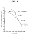
- Fig. 1 is a graph showing the relationship between the emission chromaticity (x value) and relative brightness in the same scale as to an europiumactivated yttrium oxide (hereinafter referred to as Y 2 O 3 :Eu) phosphor and Y 2 O 2 S:Eu phosphor and the characteristic of a red emission composition comprising a mixture of both the phosphors.
- Y 2 O 3 :Eu europiumactivated yttrium oxide
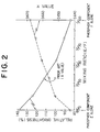
- Fig. 2 is a graph showing the relationship between the emission chromaticity (x value) and relative brightness and the mixture ratio of a Y 2 O 3 :Eu phosphor and pigment-adhered Y 2 O 2 S:Eu phosphor.
- Fig. 3 is a graph showing the relationship between the emission chromaticity (x value) and relative brightness when the concentration of the activator Eu is varied as to a Y 2 O 3 :Eu phosphor.
- Fig. 4 is a graph showing the relationship between the emission chromaticity (x value) and relative brightness when the concentration of the activator Eu is varied as to a Y 2 O 2 S:Eu phosphor.
- Fig. 5 is a graph showing change of the slurry viscosity of Y 2 O 3 :Eu phosphors of Examples 6, 8 and 9 and that of the prior art having not been subjected to an insolubilizing treatment with the passage of time.
- Fig. 6 is a graph showing change of the slurry pH of Y 2 O 3 :Eu phosphors of Examples 6, 8, 9 and 10 and that of the prior art having not been subjected to an insolubilizing treatment with the passage of time.
- Fig. 7 is a graph showing the relationship between the acid resistance and continuous slurry running time as to Y 2 O 3 : Eu phosphors of Examples 6, 8 and 9 and that of the prior art having not been subjected to an insolubilizing treatment.
- lanthanide element (Ln) of the phosphor forming the red emission composition of the present invention means at least one element of Y, Lu, Gd or La, preferably Y or a part of Y being substituted by Gd in a proportion of up to at most 70 mole %.
- europium (Eu)activator means not only Eu but also Eu containing a trace amount of at least one lanthanide element excluding the above described lanthanide elements (Ln), for example, Tb, Pr, Sm, or Dy.
- Ln is Y or Y a part of which is substituted by Gd, for example, Ln 2 O 3 :Eu, Tb phosphor, Ln 2 O 3 :Eu, Dy phosphor, Ln 2 O 2 S:Eu, Tb phosphor, Ln 2 O 2 S:Eu, Pr phosphor, Ln 2 O 2 S:Eu, Tb, Sm phosphor, Ln 2 O 2 S:Eu, Pr, Sm phosphor and the like.
- the concentration of the activator is generally 2 to 8 mole %, preferably 3 to 6 mole % for a Ln 2 O 3 type phosphor, and is generally 4 to 8 mole % for a Ln 2 O 2 S type phosphor. Furthermore, a Ln 2 O 3 type phosphor and Ln 2 O 2 S type phosphor are preferably mixed in a proportion of 85/15 to 25/75 by weight, more preferably in a proportion of 50/50 to 70/30 by weight.
- the red pigment which may be adhered to the above described phosphor may be any materials capable of hardly changing color even when heated at about 450°C, for example, iron oxide red or indium sulfide.
- the amount of the red pigment adhered to the phosphors is generally from 0.05 to 0.70 weight %, preferably 0.10 to 0.50 weight % based on the weight of the phosphor.
- the Ln 2 O 3 :Eu phosphor has somewhat been employed as a red phosphor for a color picture tube by a dusting method.
- this phosphor is chemically unstable to some extent in a coating slurry in the slurry coating method having at present been put to practical use as a method of making a fluorescent screen, is hard to be regenerated and reused and is in a much narrower range for controlling the color tone, as compared with the Ln 2 O 2 S:Eu phosphor, the former phosphor has completely been replaced by the Ln 2 O 2 S:Eu phosphor.
- the color tone can somewhat be changed as shown in Fig. 3.
- the Eu concentration means 100a mole % in the Ln 2 O 3 :Eu phosphor composition (Ln 1-a Eu a ) 2 O 3 and so forth.
- the degree of change of the color tone is smaller than that of the Ln 2 O 2 S:Eu phosphor as shown in Fig. 4.
- the inventors have found that unexpected results in solving the above described problems can be obtained by the use of a red emission composition having an x value adjusted to 0.647 to 0.662, which is obtained by mixing an Ln 2 O 3 :Eu phopshor having an x value of 0.630 to 0.652 according to CIE chromaticity representation and an Ln 2 O 2 S:Eu phopshor having an x value of 0.647 to 0.662.
- the above described red emission composition comprises preferably a mixture of an Eu-activated rare earth element oxide phopshor having an Eu concentration of 2.0 to 8.0 mole %, more preferably 3.0 to 6.0 mole % and an Eu-activated rare earth element oxysulfide phopshor having an Eu concentration of 4.0 to 8.0 mole % with a rare earth element oxide phopshor/rare earth element oxysulfide phosphor mixed weight ratio of 85/15 to 25/75, more preferably 50/50 to 70/30.
- the Ln 2 O 3 :Eu phopshor of the prior art which has not been subjected to an insolubilization treatment, tends to be slightly dissolved in a slurry to form the corresponding hydroxide, raise the pH value, aggregate the phosphor and increase the slurry viscosity with the passage of time, thus causing to change the property of the slurry.
- the phosphor slurry is generally used in a continuous and circular manner for at least several days to ten several days, the changes of pH and viscosity of the slurry during the passage of time hinders formation of fine pitch picture elements (dots, stripes) with a high density and excellent shape and unfavorably affects the quality of the resulting fluorescent film.
- the insolubilizing agent there can be used coating agents of silica type, silicon-containing organic compound type and zinc aluminate type, hydrophilicity-imparted acrylic resins and styrene-butadiene resins. Above all, it is preferable to coat the surface of a phopshor with at least one of these insolubilizing agent.
- Fig. 1 The relationship of the chromaticity (x value) and brightness between a Y 2 O 3 :Eu phosphor and R 2 O 2 S:Eu phosphor, on a same scale, is shown in Fig. 1.
- the Y 2 O 3 :Eu phosphor exhibits a varied width of color tone as represented by an x value of 0.630 to 0.652, which is smaller than that of the R 2 O 2 S:Eu phosphor, but in comparison concerning the brightness at the same chromaticity (x value), the former exhibits an about 10 to 20 % higher value than the latter.
- a red emission composition comprising a pigment-adhered Y 2 O 2 S:Eu phosphor and a pigment-free Y 2 O 3 :Eu phosphor, in combination, is most excellent. It is considered that a red pigment such as iron oxide red is localized in a Y 2 O 2 S:Eu phosphor needing improvement of the contrast, whereby the internal light absorption in a mixed system can be reduced and it is rendered possible to improve the brightness.
- a fluorescent film can more uniformly be formed with a stronger bonding strength as compared with a case of allowing the pigment adhere to either the former or the latter. This is more preferable for a color picture tube.
- the adhesion quantity of a red pigment to the above described two phosphors is respectively in the range of preferably 0.05 to 0.70 weight %, more preferably 0. 10 to 0.50 weight %.
- the Y 2 O 2 S:Eu phosphor there is generally used one whose emission color is reprsented by an x value of 0.652 to 0.674, during which the activator quantity is 4 to 8 mole %.
- the emission color is somewhat shifted to the longer wavelength side (larger x value side).
- the Eu activator quanity can be reduced by 0.1 to 0.5 mole % and in the case of a same Eu activator quantity, the emission color can be maintained in a deeper red region.
- the Eu activator quantity when using no red pigment, the Eu activator quantity is 4.0 to 8.0 mole % and when allowing a red pigment adhering, the Eu activator quantity is 3.5 to 8.0 mole %, preferably 3.8 to 8.0 mole %, which ranges are suitable in view of balance of the emission color and brightness.
- the Y 2 O 3 :Eu phosphor there is generally used one whose emission color is reprsented by an x value of 0.630 to 0.652, during which the activator quantity is 2 to 8 mole %.
- the emission color is slightly shifted to the longer wavelength side (larger x value side).
- the Eu activator quanity can be reduced by 0.03 to 0.15 mole % and in the case of a same Eu activator quantity, the emission color can slihgtly be maintained in a deeper red region.
- the Eu activator quantity when using no red pigment, is 2.0 to 8.0 mole %, preferably 3.8 to 6.0 mole % and when allowing a red pigment adhering, the Eu activator quantity is 2.0 to 8.0 mole %, preferably 2.85 to 6.0 mole %.
- the maximum value of the emission color (x value) can be increased to 0.670, 0.008 larger than 0.662 when using no red pigment, by allowing a red pigment to adhere respectively to the above described two phosphors, and consequently, the above described advantages of the present invention can be obtained.
- this red emission composition it is desirable to adjust the mixing weight ratio of (Y 2 O 3 phosphor/Y 2 O 2 S phosphor) to 85/15 to 25/75, since if the mixing weight ratio is more than 85/15, the color reproduction is degraded and if less than 25/75, the effect of improving the brightness is not sufficient.
- a preferable range of the mixing weight ratio is 50/50 to 70/30.
- the ratio of emission intensities ( ⁇ 626 / ⁇ 611 ) of the Y 2 O 2 S:Eu phosphor and Y 2 O 3 :Eu phosphor at emission peaks of 626 nm and 611 nm is in the range of 0.2 to 0.3.
- the relative brightness was improved by about 8 % to give higher brightness.
- a phosphor component C of Y 2 O 3 :Eu (Eu, 5.7 mole %) and phosphor component D of Y 2 O 2 S:Eu (Eu, 4.8 mole %) were prepared and subjected to an insolubilizing treatment in an analogous manner to Example 1 and mixed in mixing weight ratios (C/D) of 1/1 and 7/3 to obtain red emission compositions of Examples 2 and 3.
- reproduction of the chromaticity could be accomplished up to an x value of about 0.656 while maintaining the brightness superior by mixing the above described Y 2 O 3 :Eu phopshor and pigment-free Y 2 O 2 S:Eu phosphor.
- a phosphor component E of Y 2 O 3 :Eu (Eu, 3.8 mole %) and phosphor component G of Y 2 O 3 :Eu (Eu, 5.7 mole %) were prepared and subjected to an insolubilizing treatment in an analogous manner to Example 1.
- a phosphor component F of Y 2 O 2 S:Eu (Eu, 4.7 mole %) was further prepared, to which 0.5 weight % of Fe 2 O 3 pigment was adhered by a coacervation method using gelatin and gum arabic.
- phopshor components E and F were mixed in a proportion of 65/35 by weight to obtain a red emission composition of Example 4.
- this red emission composition of Example 4 was compared with a 0.15 weight % Fe 2 O 3 pigment-adhered Y 2 O 2 S:Eu phosphor (Eu, 3.8 mole %) of the prior art, having a substantially same emission chromaticity and reflectance, the relative brightness of the red emission composition of Example 4 was improved by about 12 % to give hgiher brightness.
- Fig. 2 is a graph showing changes of the emission chromaticity (x value) and relative brightness of a red emission composition, obtained when the mixing weight ratio (E/F) of the above described two phopshor components is changed.
- Example 5 the above described phosphor component G with a deep chromaticity and the above described pigment-adhered phosphor component F were mixed in a weight ratio of 65/35 to obtain a red emission composition of Example 5.
- this red emission composition of Example 5 was compared with a 0.15 weight % Fe 2 O 3 pigment-adhered Y 2 O 2 S:Eu phosphor (Eu, 4.7 mole %) of the prior art, having a substantially same emission chromaticity and reflectance, the relative brightness of the red emission composition of Example 5 was improved by about 14 % to give hgiher brightness. It is apparent from this Example that reproduction of the chromaticity could be accomplished up to an x value of about o.663, while maintaining the brightness superior.
- Example 2 100 g of a phosphor component of Y 2 O 3 :Eu (Eu, 3.8 mole %) prepared in the similar manner to Example 1 was charged in a 500 ml beaker, to which 200 ml of pure water was added, and the mixture was stirred. Furthermore, 1.25 ml of potassium water glass (PS-A -commercial name- made by Tokyo Oka KK) containing 20 % of SiO 2 was added thereto, adequately stirred, suspended and dispersed. This suspension was warmed at 70 °C with agitation and dilute acetic acid was added little by little to adjust the pH to 6.0.
- PS-A potassium water glass
- the mixture was warmed at 90 °C , stirred for 2 hours and allowed to stand for 30 minutes to precipitate a phosphor, followed by separating the supernatant by decantation and rinsing with pure water two times.
- the resulting phosphor was then filtered, dehydrated, dried at 120 °C for 15 hours, passed through a sieve of 300 mesh and subjected to an insolubilizing treatment with a silicon-type insolubilizing agent to obtain a phopshor component.
- the phosphor component When the thus obtained phosphor component was dispersed in a light-sensitive liquid of PVA-Cr type to form a slurry and changes of the slurry viscosity and pH during the passage of time were examined, the phosphor component exhibited much better stability to slurry as compared with the prior art phosphor component free from the insolubilizing treatment with potassium water glass, as shown in Fig. 5 and Fig. 6.
- the relationship of the acid resistance (insolubilizing property) and continuous using time of the slurry was similarly examined, much better property than that of the prior art article was exhibited, as shown in Fig. 7.
- Fig. 7 shows results of an accelerated test in which 10 g of the above described phosphor was added to an acidic solution of 50 ml of pure water and 1 ml of dilute acetic acid and while stirring, change of the pH of the slurry was determined during the passage of time.
- the rising of this pH value is due to that the Y 2 O 3 :Eu phosphor is dissolved to form yttrium hydroxide, thus causing aggregation of the phosphor, rising of the slurry viscosity and hindrance of a uniform coating.
- a small rising of the pH value means that the acid resistance property is excellent.
- the red emission composition of this Example 7 exhibited an improved brightness by about 12 % similar to Example 4 in comoparison with a Fe 2 O 3 pigment-adhered Y 2 O 2 S:Eu (Eu, 3.8 mole %) phosphor (iron oxide red adhered 0.15 weight %) of the prior art, having a substantially same emission chromaticity.
- Example 6 2.5 ml of a colloidal silica containing 20 % of SiO 2 (SI-500, -commercial name- made by Shokubai Kasei KK) was added in place of 1.25 ml of the potassium water glass as an insolubilizing agent of the Y 2 O 3 :Eu (Eu, 3.8 mole %) phosphor component, adequately stirred and suspended and dispersed. The resulting suspension was warmed at 50°C with agitation and dilute hydrochloric acid was added little by little to adjust the pH to 6.0.
- SI-500 -commercial name- made by Shokubai Kasei KK
- the mixture was warmed at 70 °C , stirred for 2 hours and allowed to stand for 30 minutes to precipitate a phosphor, followed by separating the supernatant by decantation and rinsing with pure water two times.
- the resulting phosphor was then filtered, dehydrated, dried at 150 °C for 10 hours, passed through a sieve of 300 mesh and subjected to an insolubilizing treatment with a silicon-type insolubilizing agent to obtain a phopshor component.
- the phosphor component When the thus obtained phosphor component was dispersed in a light-sensitive liquid of PVA-Cr type to form a slurry and changes of the slurry viscosity and pH during the passage of time were examined, the phosphor component exhibited much better stability to slurry, similar to Example 6, as compared with the prior art phopshor component free from the insolubilizing treatment with the colloidal silica as described above, as shown in Fig. 5 and Fig. 6. When the acid resistance (insolubilizing property) was also examined, much better property than that of the prior art article, similar to Example 6 was exhibited, as shown in Fig. 7.
- Example 2 100 g of a phosphor component of Y 2 O 3 :Eu (Eu, 5.7 mole %) prepared in the similar manner to Example 1 was charged in a 500 ml beaker, to which 200 ml of pure water was added, and the mixture was stirred. Furthermore, 1.25 ml of potassium water glass (PS-A -commercial name- made by Tokyo Oka KK) containing 20 % of SiO 2 was added thereto, adequately stirred, suspended and dispersed. This suspension was warmed at 70 °C with agitation and dilute acetic acid was added little by little to adjust the pH to 6.0.
- PS-A potassium water glass
- the mixture was warmed at 90 °C , stirred for 2 hours and allowed to stand for 30 minutes to precipitate a phosphor, followed by separating the supernatant by decantation and rinsing with pure water two times.
- the slurry was adequately stirred, to which an acrylic emulsion (LC-40 -commercial name- made by Nippon Acryl KK) was added in a proportion of 500 ppm to the weight of the phosphor and dilute acetic acid was further added to adjust the pH to 5.0, and the mixture was allowed to stand for 30 minutes to precipitate a phosphor, follwed by washing with pure water two times.
- an acrylic emulsion LC-40 -commercial name- made by Nippon Acryl KK
- the resulting phosphor was then filtered, dehydrated, dried at 120°C for 15 hours, passed through a sieve of 300 mesh and subjected to an insolubilizing treatment with a silicon-type insolubilizing agent and acrylic resin to obtain a phopshor component.
- Example 2 100 g of a phosphor component of Y 2 O 3 :Eu (Eu, 5.7 mole %) prepared in the similar manner to Example 1 was charged in a 500 ml beaker, to which 200 ml of pure water was added, and the mixture was stirred. Furthermore, 2.5 ml of a 20 % aqueous solution of zinc sulfate (ZnSO 4 ⁇ 7H 2 O) was added thereto, adequately stirred, suspended and dispersed. This suspension was warmed at 60 °C with agitation and dilute caustic soda was added little by little to adjust the pH to 11.0.
- ZnSO 4 ⁇ 7H 2 O zinc sulfate
- the mixture was warmed at 60°C , stirred for 1 hour, to which 5.5 ml of a 10 % aqueous solution of sodium aluminate (NaAlO 2 ) was then gradually added, followed by stirring for further 1 hour. Then, the mixture was allowed to stand for 30 minutes to precipitate a phosphor, followed by separating the supernatant by decantation and rinsing with pure water once. Pure water was added thereto, dilute acetic acid was added little by little with agitation to adjust the pH to 7.5, and the mixture was stirred for further 20 minutes, allowed to stand for 30 minutes to precipitate a phosphor, follwed by separating the supernatant by decantation and washing with pure water two times.
- NaAlO 2 sodium aluminate
- the resulting phosphor was then filtered, dehydrated, dried at 120°C for 15 hours, passed through a sieve of 300 mesh and subjected to an insolubilizing treatment with a coating agent of zinc aluminate to obtain a phopshor component.
- the phosphor component When the thus obtained phosphor component was dispersed in a light-sensitive liquid of PVA-Cr type to form a slurry and changes of the slurry viscosity and pH during the passage of time were examined, the phosphor component exhibited very good stability to slurry as shown in Fig. 6.
- Example 9 When a color picture tube was produced in an analogous manner to Example 9 except using this phosphor, similar results were obtained to Example 9.
- a cathode ray tube for color television provided with a red emission film having a satisfactory color tone and high brightness by the use of a red emission composition comprising a Ln 2 O 3 :Eu phopsphor having an excellent relative brightness property and an x value in the specified range by CIE chromaticity representation and a Ln 2 O 2 S Eu phopsphor having a deep chromaticity and an x value in the specified range by CIE chromaticity representation, or a red emission composition comprising the same phosphors but having a pigment adhered thereto.
- a color picture tube excellent in emission brightness color reproduction and beam current balance, can be obtained by combination of a fluorescent film of a green emission component having an emission color in the specified range and a fluorescent film of a blue emission component having an emission color in the specified range with a fluorescent film of this red emission component.
Landscapes
- Chemical & Material Sciences (AREA)
- Engineering & Computer Science (AREA)
- Materials Engineering (AREA)
- Organic Chemistry (AREA)
- Inorganic Chemistry (AREA)
- Luminescent Compositions (AREA)
Abstract
Description
- This invention relates to a color picture tube having a red emission composition comprising a combination of phosphors having specified emission colors on the fluorescent screen.
- Heretofore, europium activated rare earth element oxysulfide (which will hereinafter often be referred to as "Ln2O2:Eu" including, for example, "Y2O2S: Eu" for europium activated yttrium oxysulfide) phosphors have been employed as a red emitting phosphor for a color picture tube, since these phosphors each have a high emission efficiency, are capable of controlling the color tone and are chemically stable so as to be suitable for use in a slurry coating method.
- On the other hand, as one requisite for improving the properties of a color tube, it is required to enlarge the scope of color reproduction and develop therefor a red emitting phosphor having a deep chromaticity. This phosphor can readily be obtained by increasing the europium concentration, but increase of the brightness thereof is not always sufficiently obtained. In particular, as a countermeasure for the latest largesizing of a television or for a "High Definition TV" it has strongly been desired to improve the brightness, bul the situation does not satisfy the countermeasure. That is, the emission efficiency of the Ln2O2S:Eu phosphor itself has exhaustedly been improved nearly to saturation.
- As is well known in the art, other red emitting phosphors are europium activated rare earth element oxide phosphors, europium activated rare earth element vanadate phosphors, silver activated zinc cadmium sulfide phosphors and manganese activated zinc phosphate phosphors. However, none of these phosphors satisfy the above described requirements for color reproduction and brightness. Thus, there have been proposed a method comprising using a face plate containing neodymium or other elements, a method comprising providing a face plate with a special color filter on the surface thereof, and a method comprising adding a specified pigment to a fluorescent film. These methods consist in adding a filtering function to a specified wavelength of emitting colors of a phosphor to limit the transmittance of the light with the specified wavelength and thus enlarging the scope of color production. In each case, the effective brightness decrease.
- It is an object of the present invention to provide a color picture tube, which has a fluorescent film of a red emission constituent exhibiting a red emission with a deep color tone and is excellent in emission brightness, and whereby the above described problems can be solved.
- It is another object of the present invention to provide a cathode ray tube for color television, whereby the chemical stability of a europium activated rare earth element oxide (which will hereinafter often be referred to as Ln2O3:Eu) phosphor, as a red emission phosphor, is improved and the application of a slurry coating method to the above described fluorescent film of a red emission constituent is rendered possible.
- It is a further object of the present invention to provide a cathode ray tube for color television, which has an excellent emission brightness, color reproduction and beam current balance, by choosing emission colors in the specified range for those of the above described red emission constituent fluorescent film, a green emission constituent fluorescent membrane and a blue emission constituent fluorescent film.
- The present invention provides a color picture tube having a face plate on which dot-shaped or stripe-shaped fluorescent films of blue, green and red emission components are respectively formed characterised in that the fluorescent film of the red emission component comprises a mixture of a red emission composition comprising a europium activated rare earth element oxide phosphor having an x value of 0.630 to 0.652 in CIE Chromaticity Representation and a europium activated rare earth element oxysulfide phosphor having an x value of 0.652 to 0.674 in the same representation, the said mixture having an x value of 0.647 to 0.662 in the same representation.
- In a preferred embodiment of the present invention, a color picture tube is provided in which the above described europium activated rare earth oxide phosphor is subjected to an insolubilization treatment of the surface thereof and the above described fluorescent films of blue, green and red emission components are respectively formed by the slurry coating method.
- In a further preferred embodiment of the present invention, a color picture tube is provided in which the emission colors of the green emission fluorescent film and blue emission fluorescent film are respectively in the range of x of 0.200 to 0.330 and 0.145 to 0.155 in CIE Chromaticity Representation.
- The present invention will be further described with reference to the accompanying drawings, in which:
- Fig. 1 is a graph showing the relationship between the emission chromaticity (x value) and relative brightness in the same scale as to an europiumactivated yttrium oxide (hereinafter referred to as Y2O3 :Eu) phosphor and Y2O2S:Eu phosphor and the characteristic of a red emission composition comprising a mixture of both the phosphors.
- Fig. 2 is a graph showing the relationship between the emission chromaticity (x value) and relative brightness and the mixture ratio of a Y2O3:Eu phosphor and pigment-adhered Y2O2S:Eu phosphor.
- Fig. 3 is a graph showing the relationship between the emission chromaticity (x value) and relative brightness when the concentration of the activator Eu is varied as to a Y2O3 :Eu phosphor.
- Fig. 4 is a graph showing the relationship between the emission chromaticity (x value) and relative brightness when the concentration of the activator Eu is varied as to a Y2O2S:Eu phosphor.
- Fig. 5 is a graph showing change of the slurry viscosity of Y2O3 :Eu phosphors of Examples 6, 8 and 9 and that of the prior art having not been subjected to an insolubilizing treatment with the passage of time.
- Fig. 6 is a graph showing change of the slurry pH of Y2O3 :Eu phosphors of Examples 6, 8, 9 and 10 and that of the prior art having not been subjected to an insolubilizing treatment with the passage of time.
- Fig. 7 is a graph showing the relationship between the acid resistance and continuous slurry running time as to Y2O3 : Eu phosphors of Examples 6, 8 and 9 and that of the prior art having not been subjected to an insolubilizing treatment.
- The term "lanthanide element (Ln)" of the phosphor forming the red emission composition of the present invention means at least one element of Y, Lu, Gd or La, preferably Y or a part of Y being substituted by Gd in a proportion of up to at most 70 mole %. The term "europium (Eu)activator" means not only Eu but also Eu containing a trace amount of at least one lanthanide element excluding the above described lanthanide elements (Ln), for example, Tb, Pr, Sm, or Dy. Specifically, it is preferable to use such a phosphor that Ln is Y or Y a part of which is substituted by Gd, for example, Ln2O3:Eu, Tb phosphor, Ln2O3 :Eu, Dy phosphor, Ln2O2S:Eu, Tb phosphor, Ln2O2S:Eu, Pr phosphor, Ln2O2S:Eu, Tb, Sm phosphor, Ln2O2S:Eu, Pr, Sm phosphor and the like. The concentration of the activator is generally 2 to 8 mole %, preferably 3 to 6 mole % for a Ln2O3 type phosphor, and is generally 4 to 8 mole % for a Ln2O2S type phosphor. Furthermore, a Ln2O3 type phosphor and Ln2O2S type phosphor are preferably mixed in a proportion of 85/15 to 25/75 by weight, more preferably in a proportion of 50/50 to 70/30 by weight.
- The red pigment which may be adhered to the above described phosphor, may be any materials capable of hardly changing color even when heated at about 450°C, for example, iron oxide red or indium sulfide. The amount of the red pigment adhered to the phosphors is generally from 0.05 to 0.70 weight %, preferably 0.10 to 0.50 weight % based on the weight of the phosphor.
- Up to the present time, the Ln2O3:Eu phosphor has somewhat been employed as a red phosphor for a color picture tube by a dusting method. However, since this phosphor is chemically unstable to some extent in a coating slurry in the slurry coating method having at present been put to practical use as a method of making a fluorescent screen, is hard to be regenerated and reused and is in a much narrower range for controlling the color tone, as compared with the Ln2O2S:Eu phosphor, the former phosphor has completely been replaced by the Ln2O2S:Eu phosphor.
- When the Eu concentration of the Ln2O3:Eu phosphor is changed from 3 to 4 mole % in the prior art to 8 mole %, the color tone can somewhat be changed as shown in Fig. 3. Herein, the Eu concentration means 100a mole % in the Ln2O3:Eu phosphor composition (Ln1-a Eu a )2O 3 and so forth. However, the degree of change of the color tone is smaller than that of the Ln2O2S:Eu phosphor as shown in Fig. 4.
- Noting the properties of the Ln2O3:Eu phosphor, i.e. a slight change of the emission color and a high emission luminance, and the properties of the Ln2O2S:Eu phosphor, i.e. a large change of the emission color with the Eu concentration and a relatively low emission brightness, the inventors have found that unexpected results in solving the above described problems can be obtained by the use of a red emission composition having an x value adjusted to 0.647 to 0.662, which is obtained by mixing an Ln2O3:Eu phopshor having an x value of 0.630 to 0.652 according to CIE chromaticity representation and an Ln2O2S:Eu phopshor having an x value of 0.647 to 0.662.
- The above described red emission composition comprises preferably a mixture of an Eu-activated rare earth element oxide phopshor having an Eu concentration of 2.0 to 8.0 mole %, more preferably 3.0 to 6.0 mole % and an Eu-activated rare earth element oxysulfide phopshor having an Eu concentration of 4.0 to 8.0 mole % with a rare earth element oxide phopshor/rare earth element oxysulfide phosphor mixed weight ratio of 85/15 to 25/75, more preferably 50/50 to 70/30.
- On the other hand, the Ln2O3:Eu phopshor of the prior art, which has not been subjected to an insolubilization treatment, tends to be slightly dissolved in a slurry to form the corresponding hydroxide, raise the pH value, aggregate the phosphor and increase the slurry viscosity with the passage of time, thus causing to change the property of the slurry. Since the phosphor slurry is generally used in a continuous and circular manner for at least several days to ten several days, the changes of pH and viscosity of the slurry during the passage of time hinders formation of fine pitch picture elements (dots, stripes) with a high density and excellent shape and unfavorably affects the quality of the resulting fluorescent film.
- According to the present invention, application of the Ln2O3:Eu phopshor to the above described red emission composition is rendered possible by subjecting the surface thereof to an insolubilizing treatment, improving the chemical stability thereof in a coating slurry and thus maintaining the stability to the slurry and the coating stability.
- As the insolubilizing agent, there can be used coating agents of silica type, silicon-containing organic compound type and zinc aluminate type, hydrophilicity-imparted acrylic resins and styrene-butadiene resins. Above all, it is preferable to coat the surface of a phopshor with at least one of these insolubilizing agent.
- The present invention will now be illustrated in detail in the case of Y as a typical example of Ln, but is not intended to be limited thereto.
- The relationship of the chromaticity (x value) and brightness between a Y2O3:Eu phosphor and R2O2S:Eu phosphor, on a same scale, is shown in Fig. 1. As is evident from Fig. 1, the Y2O3:Eu phosphor exhibits a varied width of color tone as represented by an x value of 0.630 to 0.652, which is smaller than that of the R2O2S:Eu phosphor, but in comparison concerning the brightness at the same chromaticity (x value), the former exhibits an about 10 to 20 % higher value than the latter.
- According to the present invention, a red emission with a deep color tone in the range of x = 0.647 - 0.662 having lately been desired as to enalrgement of the range of color reproduction can be obtained by combining the Y2O3:Eu phosphor excellent in brightness and the Y2O2S:Eu phosphor with a deep color tone, i.e. a large x value, and moreover, the brightness can considerably be improved as compared with the case of using the Y2O2S:Eu phosphor of the prior art or pigment-adhered phosphor thereof alone.
- The effects or advanatges by the above described joint use are, as shown in Fig. 1, that when a Y2O3:Eu phosphor with an x value of 0.643 and brightness of 138 % (point A) is mixed with a Y2O2S:Eu phosphor with an x value of 0.662 and brightness of 101 % (point B), a red emission composition with an x value of 0.652 and brightness of 120 % can be obtained, which gives an improved brightness by about 8 % as compared with the Y2O2S:Eu phosphor with the same chromaticity (Eu activator quantity 4.0 mole %, x value 0.652, relative brightness 112 %) alone. This red emission composition is in the region of color tone which has been used at the present time.
- The foregoing illustration is related with the joint use of pigment-free phosphors, but the effects by the joint use can also be given in the case of pigment-adhered phosphors. Above all, a red emission composition comprising a pigment-adhered Y2O2S:Eu phosphor and a pigment-free Y2O3:Eu phosphor, in combination, is most excellent. It is considered that a red pigment such as iron oxide red is localized in a Y2O2S:Eu phosphor needing improvement of the contrast, whereby the internal light absorption in a mixed system can be reduced and it is rendered possible to improve the brightness.
- However, when a red pigment such as iron oxide red is adhered to both of a Y2O2S:Eu phosphor and Y2O3:Eu phosphor, a fluorescent film can more uniformly be formed with a stronger bonding strength as compared with a case of allowing the pigment adhere to either the former or the latter. This is more preferable for a color picture tube.
- In the present invention, the adhesion quantity of a red pigment to the above described two phosphors is respectively in the range of preferably 0.05 to 0.70 weight %, more preferably 0. 10 to 0.50 weight %.
- As the Y2O2S:Eu phosphor, there is generally used one whose emission color is reprsented by an x value of 0.652 to 0.674, during which the activator quantity is 4 to 8 mole %. When a red pigemnt is allowed to adhere to this phosphor, the emission color is somewhat shifted to the longer wavelength side (larger x value side). Thus, in the case of obtaining a same emission color, the Eu activator quanity can be reduced by 0.1 to 0.5 mole % and in the case of a same Eu activator quantity, the emission color can be maintained in a deeper red region. That is, when using no red pigment, the Eu activator quantity is 4.0 to 8.0 mole % and when allowing a red pigment adhering, the Eu activator quantity is 3.5 to 8.0 mole %, preferably 3.8 to 8.0 mole %, which ranges are suitable in view of balance of the emission color and brightness.
- As the Y2O3:Eu phosphor, there is generally used one whose emission color is reprsented by an x value of 0.630 to 0.652, during which the activator quantity is 2 to 8 mole %. When a red pigemnt is allowed to adhere to this phosphor, the emission color is slightly shifted to the longer wavelength side (larger x value side). Thus, in the case of obtaining a same emission color, the Eu activator quanity can be reduced by 0.03 to 0.15 mole % and in the case of a same Eu activator quantity, the emission color can slihgtly be maintained in a deeper red region. That is, when using no red pigment, the Eu activator quantity is 2.0 to 8.0 mole %, preferably 3.8 to 6.0 mole % and when allowing a red pigment adhering, the Eu activator quantity is 2.0 to 8.0 mole %, preferably 2.85 to 6.0 mole %.
- In the present invention, as described above, the maximum value of the emission color (x value) can be increased to 0.670, 0.008 larger than 0.662 when using no red pigment, by allowing a red pigment to adhere respectively to the above described two phosphors, and consequently, the above described advantages of the present invention can be obtained.
- In order to obtain this red emission composition, it is desirable to adjust the mixing weight ratio of (Y2O3 phosphor/Y2O2S phosphor) to 85/15 to 25/75, since if the mixing weight ratio is more than 85/15, the color reproduction is degraded and if less than 25/75, the effect of improving the brightness is not sufficient. A preferable range of the mixing weight ratio is 50/50 to 70/30.
- In the thus obtained red emission composition, the ratio of emission intensities ( λ 626/λ 611) of the Y2O2S:Eu phosphor and Y2O3:Eu phosphor at emission peaks of 626 nm and 611 nm is in the range of 0.2 to 0.3.
- The present invention will be illustrated in detail by the following eamples without limiting the same.
- 226 g of yttrium oxide and 14.1 g of europium oxide were dissolved in hydrochloric acid, treated with oxalic acid to form coprecipitated oxalates and decomposed at 1000 °C to obtain (Y0. 962Eu0. 038)2O3. Then, 0.05 weight % of B2O3 as a flux was added thereto and fired at 1450°C to obtain a phophor component of Y2O3:Eu (Eu, 3.8 mole %). The resulting phosphor component was subjected to a dispersing treatment in a ball mill and then to a surface treatment with a coating agent of zinc aluminate type and finished by drying. In addition, 0.4 %, on dry basis, of GeO2, as a pH rising inhibitor, was added thereto to obtain a phopshor component A.
- On the other hand, in order to correct the chromaticity of the above described phopshor component, another phopshor component B of Y2O2S:Eu (Eu, 4.8 mole %) with a deep chromaticity, i.e. high concentration Eu was prepared.
- These phosphor components were mixed in a mixing weight ratio (A/B) of 1/1 to form a red emission composition of Example 1.
- When the properties of the red emission composition and mixed components were measured using a Demantable's electron beam stimulus apparatus at conditions of 20 kV and 1.0 µ A/cm2, it was found as shown in Table 1 that the relative brightness was increased by about 7 % to give a higher brightness as compared with a Y2O2S:Eu phosphor (Eu, 4.0 mole %) of the prior art, having the same emission chromaticity as the red emission composition of Example 1.
- When the above described red emission composition was converted into a slurry using a light-sensitive liquid of PVA-Cr type, coated onto a panel and subjected to measurement of the brightness of a monochrome red cathode ray tube, the relative brightness was improved by about 8 % to give higher brightness.
Table 1 Emission x Chromaticity y Relative Brightness (%) Phosphor Component A, Y2O3:Eu (Eu, 3.8 mole %) 0.643 0.351 123 Phosphor Component B, Y2O2S:Eu (Eu, 4.8 mole %) 0.662 0.333 90 Example 1, Mixed Phosphors (A/B=1/1) 0.652 0.342 107 Y2O2S:Eu (Eu, 4.0 mole %) of the Prior Art 0.652 0.340 100 Fluorescent Surface coated with Mixed Phosphors (A/B = 1/1) 0.651 0.340 108 Fluorescent Surface coated with Phosphors of the Prior Art 0.652 0.340 100 - A phosphor component C of Y2O3:Eu (Eu, 5.7 mole %) and phosphor component D of Y2O2S:Eu (Eu, 4.8 mole %) were prepared and subjected to an insolubilizing treatment in an analogous manner to Example 1 and mixed in mixing weight ratios (C/D) of 1/1 and 7/3 to obtain red emission compositions of Examples 2 and 3. When these red emission phopshors and red emission compositions were compared with a Y2O2S:Eu phosphor (Eu, 4.2 mole %) of the prior art and a Y2O2S:Eu phosphor (Eu, 4.0 mole %) of the prior art, each having a substantially same emission color, as shown in Table 2, the relative brightness of the red emission compositions of Examples 2 and 3 were improved by about 6 % and about 8 % to give hgiher brightness. As evident from the mixing weight ratio (C/D) of Table 2, when a more shallow chromaticity was reproduced, the mixing ratio of the phosphor component C of Y2O3:Eu was increased and the relative brightness was improved by about 2 %. Moreover, reproduction of the chromaticity could be accomplished up to an x value of about 0.656 while maintaining the brightness superior by mixing the above described Y2O3:Eu phopshor and pigment-free Y2O2S:Eu phosphor.
Table 2 Emission x Chromaticity y Relative Brightness (%) Phosphor Component C, Y2O3:Eu (Eu, 5.7 mole %) 0.650 0.346 117 Phosphor Component D, Y2O2S:Eu (Eu, 4.8 mole %) 0.662 0.333 96 Example 2, Mixed Phosphors (C/D=1/1) 0.656 0.339 106 Y2O2S:Eu (Eu, 4.2 mole %) of the Prior Art 0.656 0.339 100 Example 3, Mixed Phosphors (C/D=7/3) 0.653 0.341 108 Y2O2S:Eu (Eu, 4.2 mole %) of the Prior Art 0.653 0.339 100 - A phosphor component E of Y2O3:Eu (Eu, 3.8 mole %) and phosphor component G of Y2O3:Eu (Eu, 5.7 mole %) were prepared and subjected to an insolubilizing treatment in an analogous manner to Example 1. A phosphor component F of Y2O2S:Eu (Eu, 4.7 mole %) was further prepared, to which 0.5 weight % of Fe2O3 pigment was adhered by a coacervation method using gelatin and gum arabic.
- Firstly, the phopshor components E and F were mixed in a proportion of 65/35 by weight to obtain a red emission composition of Example 4. When this red emission composition of Example 4 was compared with a 0.15 weight % Fe2O3 pigment-adhered Y2O2S:Eu phosphor (Eu, 3.8 mole %) of the prior art, having a substantially same emission chromaticity and reflectance, the relative brightness of the red emission composition of Example 4 was improved by about 12 % to give hgiher brightness. Fig. 2 is a graph showing changes of the emission chromaticity (x value) and relative brightness of a red emission composition, obtained when the mixing weight ratio (E/F) of the above described two phopshor components is changed.
- Then, the above described phosphor component G with a deep chromaticity and the above described pigment-adhered phosphor component F were mixed in a weight ratio of 65/35 to obtain a red emission composition of Example 5. When this red emission composition of Example 5 was compared with a 0.15 weight % Fe2O3 pigment-adhered Y2O2S:Eu phosphor (Eu, 4.7 mole %) of the prior art, having a substantially same emission chromaticity and reflectance, the relative brightness of the red emission composition of Example 5 was improved by about 14 % to give hgiher brightness. It is apparent from this Example that reproduction of the chromaticity could be accomplished up to an x value of about o.663, while maintaining the brightness superior.
-
Table 3 Emission x Chromaticity y Relative Brightness (%) Reflectance (%) (500 nm) Phosphor Component E, (500 nm) Y2O3:Eu (Eu, 3.8 mole %) 0.643 0.351 138 97.0 Phosphor Component F, 0.5 % pigment-adhered Y2O2S:Eu (Eu, 4.7 mole %) 0.668 0.328 84 30.5 Example 4, Mixed Phosphors (E/F = 65/35) 0.656 0.337 112 51.9 0.15 % pigment-adhered Y2O2S:Eu (Eu, 3.8 mole %) of the Prior Art 0.655 0.340 100 51.0 Phosphor Component G, Y2O3:Eu (Eu, 5.7 mole %) 0.650 0.346 127 97.0 Phosphor Component H, 0.5 % pigment-adhered Y2O2S:Eu (Eu, 4.7 mole %) 0.668 0.328 84 30.5 Example 5, Mixed Phosphors (G/F = 65/35) 0.663 0.334 114 52.3 0.15 % pigment-adhered Y2O2S:Eu (Eu, 4.7 mole %) of the Prior Art 0.663 0.333 100 51.0 - 100 g of a phosphor component of Y2O3:Eu (Eu, 3.8 mole %) prepared in the similar manner to Example 1 was charged in a 500 ml beaker, to which 200 ml of pure water was added, and the mixture was stirred. Furthermore, 1.25 ml of potassium water glass (PS-A -commercial name- made by Tokyo Oka KK) containing 20 % of SiO2 was added thereto, adequately stirred, suspended and dispersed. This suspension was warmed at 70 °C with agitation and dilute acetic acid was added little by little to adjust the pH to 6.0. Then, the mixture was warmed at 90 °C , stirred for 2 hours and allowed to stand for 30 minutes to precipitate a phosphor, followed by separating the supernatant by decantation and rinsing with pure water two times. The resulting phosphor was then filtered, dehydrated, dried at 120 °C for 15 hours, passed through a sieve of 300 mesh and subjected to an insolubilizing treatment with a silicon-type insolubilizing agent to obtain a phopshor component.
- When the thus obtained phosphor component was dispersed in a light-sensitive liquid of PVA-Cr type to form a slurry and changes of the slurry viscosity and pH during the passage of time were examined, the phosphor component exhibited much better stability to slurry as compared with the prior art phosphor component free from the insolubilizing treatment with potassium water glass, as shown in Fig. 5 and Fig. 6. When the relationship of the acid resistance (insolubilizing property) and continuous using time of the slurry was similarly examined, much better property than that of the prior art article was exhibited, as shown in Fig. 7.
- Fig. 7 shows results of an accelerated test in which 10 g of the above described phosphor was added to an acidic solution of 50 ml of pure water and 1 ml of dilute acetic acid and while stirring, change of the pH of the slurry was determined during the passage of time. The rising of this pH value is due to that the Y2O3:Eu phosphor is dissolved to form yttrium hydroxide, thus causing aggregation of the phosphor, rising of the slurry viscosity and hindrance of a uniform coating. In other words, a small rising of the pH value means that the acid resistance property is excellent.
- When a Y2O2S:Eu (Eu, 4.8 mole %) phosphor component was added to the above described phosphor component to obtain a light-sensitive liquid of PVA-Cr type and coated onto a panel to obtain a monochrome red cathode ray tube an analogous manner to Example 1, the relative brightness was improved by about 8 % similar to Example 1.
- Furthermore, when using a ZuS:Cu, Al (Cu, 65 ppm) phosphor having an x value of 0.281 and y value of 0.619, as a green emission phosphor, and a ZnS:Ag, Al (Ag, 300 ppm) phosphor having an x value of 0.149 and y value of 0.050, as a blue emission phosphor, in addition to the above described red emission composition (x value 0.652, y value 0.342) to produce a color picture tube, this color picture tube exhibited a more excellent color reproduction region, emission brightness and beam current balance than that using a red emission phosphor of the prior art.
- When a similar test to above described was carried out using a (Y0. 5Gd0. 5)2O3:Eu (Eu, 3.8 mole %) phopshor component instead of the above described Y2O3:Eu (Eu, 3.8 mole %) phopshor component, the similar advantages were obtained to described above.
- To a Y2O3:Eu (Eu, 3.8 mole %) phopshor, subjected to an insolubilizing treatment in the similar manner to Example 6, was adhered 0.20 weight % of a Fe2O3 pigmnent by a coacervation method using gelatin and gum arabic to prepare a phopshor component I.
- Similarly, 0.15 weight % of the Fe2O3 pigmnent was adhered to a Y2O2S:Eu (Eu, 4.8 mole %) phosphor to prepare a phopshor component J.
- The above described phosphor components I and J were mixed in a mixing ratio of 65/35 to obtain a red emission composition.
- The red emission composition of this Example 7 exhibited an improved brightness by about 12 % similar to Example 4 in comoparison with a Fe2O3 pigment-adhered Y2O2S:Eu (Eu, 3.8 mole %) phosphor (iron oxide red adhered 0.15 weight %) of the prior art, having a substantially same emission chromaticity.
-
Table 4 Emission x Chromaticity y Relative Brightness (%) Phosphor Component I, 0.2 wt% pigment-adhered Y2O3:Eu (Eu, 3.8 mole %) 0.650 0.346 126 Phosphor Component J, 0.15 wt% pigment-adhered Y2O2S:Eu (Eu, 4.7 mole %) 0.667 0.328 90 Example 10, Mixed Phosphors (I/J = 65/35) 0.656 0.337 112 0.15 wt% pigment-adhered Y2O2S:Eu (Eu, 3.8 mole %) of the Prior Art 0.655 0.340 100 - In Example 6, 2.5 ml of a colloidal silica containing 20 % of SiO2 (SI-500, -commercial name- made by Shokubai Kasei KK) was added in place of 1.25 ml of the potassium water glass as an insolubilizing agent of the Y2O3:Eu (Eu, 3.8 mole %) phosphor component, adequately stirred and suspended and dispersed. The resulting suspension was warmed at 50°C with agitation and dilute hydrochloric acid was added little by little to adjust the pH to 6.0. Then, the mixture was warmed at 70 °C , stirred for 2 hours and allowed to stand for 30 minutes to precipitate a phosphor, followed by separating the supernatant by decantation and rinsing with pure water two times. The resulting phosphor was then filtered, dehydrated, dried at 150 °C for 10 hours, passed through a sieve of 300 mesh and subjected to an insolubilizing treatment with a silicon-type insolubilizing agent to obtain a phopshor component.
- When the thus obtained phosphor component was dispersed in a light-sensitive liquid of PVA-Cr type to form a slurry and changes of the slurry viscosity and pH during the passage of time were examined, the phosphor component exhibited much better stability to slurry, similar to Example 6, as compared with the prior art phopshor component free from the insolubilizing treatment with the colloidal silica as described above, as shown in Fig. 5 and Fig. 6. When the acid resistance (insolubilizing property) was also examined, much better property than that of the prior art article, similar to Example 6 was exhibited, as shown in Fig. 7.
- When using the green emission phosphor and blue emission phosphor in addition to the above described red emission composition to obtain a color picture tube in an analogous manner to Example 6, the similar advantages were obtained to Example 6.
- 100 g of a phosphor component of Y2O3:Eu (Eu, 5.7 mole %) prepared in the similar manner to Example 1 was charged in a 500 ml beaker, to which 200 ml of pure water was added, and the mixture was stirred. Furthermore, 1.25 ml of potassium water glass (PS-A -commercial name- made by Tokyo Oka KK) containing 20 % of SiO2 was added thereto, adequately stirred, suspended and dispersed. This suspension was warmed at 70 °C with agitation and dilute acetic acid was added little by little to adjust the pH to 6.0. Then, the mixture was warmed at 90 °C , stirred for 2 hours and allowed to stand for 30 minutes to precipitate a phosphor, followed by separating the supernatant by decantation and rinsing with pure water two times. The slurry was adequately stirred, to which an acrylic emulsion (LC-40 -commercial name- made by Nippon Acryl KK) was added in a proportion of 500 ppm to the weight of the phosphor and dilute acetic acid was further added to adjust the pH to 5.0, and the mixture was allowed to stand for 30 minutes to precipitate a phosphor, follwed by washing with pure water two times. The resulting phosphor was then filtered, dehydrated, dried at 120°C for 15 hours, passed through a sieve of 300 mesh and subjected to an insolubilizing treatment with a silicon-type insolubilizing agent and acrylic resin to obtain a phopshor component.
- When the thus obtained phosphor component was dispersed in a light-sensitive liquid of PVA-Cr type to form a slurry and changes of the slurry viscosity and pH during the passage of time were examined, the phosphor component exhibited much better stability to slurry as compared with the prior art phosphor component free from the insolubilizing treatment, as shown in Fig. 5 and Fig. 6. When the acid resistance (insolubilizing property) was also examined, much better property than that of the prior art article was exhibited, as shown in Fig. 7. When the red emission composition of Example 2 was similarly used, similar advantages to Example 2 were obtained.
- Furthermore, when using a green emission phosphor composition having an x value of 0.277 and y value of 0.630 [mixture of ZnS:Cu, Al(Cu activator quantity 65 ppm) phosphor and Zn2SiO4:Mn phosphor] and a ZnS:Ag, Al (Ag activator quantity 300 ppm) phosphor having an x value of 0.149 and y value of 0.050, as a blue emission phosphor, in addition to the above described red emission composition (x value 0.656, y value 0.339) to produce a color television cathode ray tube, this color picture tube exhibited a more excellent color reproduction region, emission brightness and beam current balance than that using a red emission phosphor of the prior art.
- When a similar test to above described was carried out using a (Y0. 7Gd0. 3)2O3:Eu (Eu, 5.7 mole %) phopshor component instead of the above described Y2O3:Eu (Eu, 5.7 mole %) phopshor component, the similar advantages were obtained to described above.
- 100 g of a phosphor component of Y2O3:Eu (Eu, 5.7 mole %) prepared in the similar manner to Example 1 was charged in a 500 ml beaker, to which 200 ml of pure water was added, and the mixture was stirred. Furthermore, 2.5 ml of a 20 % aqueous solution of zinc sulfate (ZnSO4 · 7H2O) was added thereto, adequately stirred, suspended and dispersed. This suspension was warmed at 60 °C with agitation and dilute caustic soda was added little by little to adjust the pH to 11.0. Then, the mixture was warmed at 60°C , stirred for 1 hour, to which 5.5 ml of a 10 % aqueous solution of sodium aluminate (NaAlO2) was then gradually added, followed by stirring for further 1 hour. Then, the mixture was allowed to stand for 30 minutes to precipitate a phosphor, followed by separating the supernatant by decantation and rinsing with pure water once. Pure water was added thereto, dilute acetic acid was added little by little with agitation to adjust the pH to 7.5, and the mixture was stirred for further 20 minutes, allowed to stand for 30 minutes to precipitate a phosphor, follwed by separating the supernatant by decantation and washing with pure water two times. The resulting phosphor was then filtered, dehydrated, dried at 120°C for 15 hours, passed through a sieve of 300 mesh and subjected to an insolubilizing treatment with a coating agent of zinc aluminate to obtain a phopshor component.
- When the thus obtained phosphor component was dispersed in a light-sensitive liquid of PVA-Cr type to form a slurry and changes of the slurry viscosity and pH during the passage of time were examined, the phosphor component exhibited very good stability to slurry as shown in Fig. 6.
- When a color picture tube was produced in an analogous manner to Example 9 except using this phosphor, similar results were obtained to Example 9.
- According to the present invention, there can be provided a cathode ray tube for color television, provided with a red emission film having a satisfactory color tone and high brightness by the use of a red emission composition comprising a Ln2O3:Eu phopsphor having an excellent relative brightness property and an x value in the specified range by CIE chromaticity representation and a Ln2O2S Eu phopsphor having a deep chromaticity and an x value in the specified range by CIE chromaticity representation, or a red emission composition comprising the same phosphors but having a pigment adhered thereto. Furthermore, it is thus rendered possible to obtain a color picture tube, excellent in emission brightness color reproduction and beam current balance, can be obtained by combination of a fluorescent film of a green emission component having an emission color in the specified range and a fluorescent film of a blue emission component having an emission color in the specified range with a fluorescent film of this red emission component.
Claims (14)
- A color picture tube, having a face plate on which dot-shaped or stripe-shaped fluorescent films of blue, green and red emission components are respectively formed, characterized in that the fluorescent film of the red emission component comprises a mixture of a red emission composition comprising a europium activated rare earth element oxide phosphor having an x value of 0.630 to 0.652 in CIE Chromaticity Representation and a europium activated rare earth element oxysulfide phosphor having an x value of 0.652 to 0.674 in the same representation, the said mixture having an x value of 0.647 to 0.662 in the same representation.
- A color picture tube as claimed in Claim 1, wherein the red emission composition comprises a mixture of a europium-activated rare earth element oxide phosphor having a europium concentration of 2.0 to 8.0 mole % and a europium-activated rare earth element oxysulfide phosphor having a europium concentration of 4.0 to 8.0 mole % in a mixing weight ratio (rare earth element oxide phosphor/rare earth element oxysulfide phosphor) of 85/15 to 25/75.
- A color picture tube as claimed in Claim 2, wherein the mixing weight ratio of the europium-activated rare earth element oxide phosphor and the europium-activated rare earth element oxysulfide phosphor (rare earth element oxide phosphor/rare earth element oxysulfide phosphor) is in the range of 50/50 to 70/30.
- A color picture tube as claimed in any one of the preceding claims, wherein the red emission composition further comprises a red pigment.
- A color picture tube as claimed in Claim 4, wherein the red emission composition comprises pigment-adhered phosphors obtained by adhering a red pigment to the europium-activated rare earth element oxysulfide phosphor and the europium-activated rare earth element oxide phosphor, respectively.
- A color picture tube as claimed in Claim 4, wherein the red emission composition comprises a mixture of a red pigment-adhered europium-activated rare earth element oxide phosphor with a europium concentration of 2.0 to 8.0 mole % and a red pigment-adhered europium-activated rare earth element oxysulfide phosphor with a europium concentration of 3.5 to 8.0 mole % in a mixing weight ratio (rare earth element oxide phosphor/rare earth element oxysulfide phosphor) of 85/15 to 25/75.
- A color picture tube, as claimed in any one of Claims 4 to 6, wherein the red pigment is iron oxide red.
- A color picture tube, as claimed in any one of Claims 4 to 7, wherein the adhesion quantity of the iron oxide red is in the range of 0.05 to 0.70 weight %.
- A color picture tube as claimed in any one of the preceding claims, wherein the emission colors of a green emission fluorescent film and a blue emission fluorescent film are represented by x values of 0.200 to 0.330 and 0.145 to 0.155 in CIE chromaticity representation, respectively.
- A color picture tube as claimed in Claim 1, wherein the red emission composition comprises a europium activated yttrium oxysulfide phosphor and a europium activated yttrium oxide phosphor with an emission intensity ratio (λ626/λ611) of 0.2 to 3.0 at emission peaks of 620 nm and 611 nm.
- A color picture tube as claimed in Claim 1, wherein the europium activated rare earth oxide phosphor is subjected to an insolubilization treatment of the surface thereof and fluorescent films of blue, green and red emission components are respectively formed by a slurry coating method.
- A color picture tube as claimed in Claim 11, wherein the europium activated rare earth oxide phosphor is subjected to an insolubilization treatment by coating the phosphor surface with a hydrophilic insolubilizing agent.
- A color picture tube as claimed in Claim 12, wherein the hydrophilic insolubilizing agent is a silicon type or a zinc oxide aluminate type treating agent.
- A color picture tube, as claimed in Claim 12, wherein the hydrophilic insolubilizing agent is an acrylic resin or a styrene-butadiene resin, to which hydrophilic properties have been imparted.
Applications Claiming Priority (3)
| Application Number | Priority Date | Filing Date | Title |
|---|---|---|---|
| JP4968391 | 1991-03-14 | ||
| JP49683/91 | 1991-03-14 | ||
| PCT/JP1992/000309 WO1992016598A1 (en) | 1991-03-14 | 1992-03-13 | Color cathode-ray tube |
Publications (3)
| Publication Number | Publication Date |
|---|---|
| EP0529098A1 EP0529098A1 (en) | 1993-03-03 |
| EP0529098A4 EP0529098A4 (en) | 1993-08-04 |
| EP0529098B1 true EP0529098B1 (en) | 1996-11-27 |
Family
ID=12837980
Family Applications (1)
| Application Number | Title | Priority Date | Filing Date |
|---|---|---|---|
| EP92906681A Expired - Lifetime EP0529098B1 (en) | 1991-03-14 | 1992-03-13 | Color cathode-ray tube |
Country Status (6)
| Country | Link |
|---|---|
| US (1) | US5394055A (en) |
| EP (1) | EP0529098B1 (en) |
| KR (1) | KR0184292B1 (en) |
| CA (1) | CA2082961C (en) |
| DE (1) | DE69215453T2 (en) |
| WO (1) | WO1992016598A1 (en) |
Families Citing this family (10)
| Publication number | Priority date | Publication date | Assignee | Title |
|---|---|---|---|---|
| KR950701374A (en) * | 1993-02-26 | 1995-03-23 | 사토 후미오 | Phosphor and fluorescent lamp using the same |
| JP2809084B2 (en) * | 1994-01-28 | 1998-10-08 | 双葉電子工業株式会社 | Field emission fluorescent display |
| KR0144194B1 (en) * | 1995-04-17 | 1998-07-01 | 구자홍 | Color Brown Tube Fluorescent Film Structure |
| US5858616A (en) * | 1995-10-13 | 1999-01-12 | Hitachi Chemical Company, Ltd. | Photosensitive resin composition, photosensitive film and process for preparing fluorescent pattern using the same, and phosphor subjected to surface treatment and process for preparing the same |
| JP3276105B2 (en) * | 1996-10-08 | 2002-04-22 | 松下電器産業株式会社 | Color picture tube |
| JPH10195432A (en) * | 1997-01-14 | 1998-07-28 | Toshiba Corp | Fluorescent substance for plasma display panel |
| US6157126A (en) * | 1997-03-13 | 2000-12-05 | Matsushita Electric Industrial Co., Ltd. | Warm white fluorescent lamp |
| JPH10334823A (en) * | 1997-06-04 | 1998-12-18 | Toshiba Corp | Color image-receiving tube |
| KR100636447B1 (en) | 2002-12-26 | 2006-10-18 | 가부시끼가이샤 도시바 | Display |
| US7601276B2 (en) * | 2004-08-04 | 2009-10-13 | Intematix Corporation | Two-phase silicate-based yellow phosphor |
Family Cites Families (11)
| Publication number | Priority date | Publication date | Assignee | Title |
|---|---|---|---|---|
| JPS50132864A (en) * | 1974-04-05 | 1975-10-21 | ||
| JPS513775A (en) * | 1974-06-28 | 1976-01-13 | Mitsubishi Electric Corp | KARAAINKYOKUSENKAN |
| JPS5219187A (en) * | 1975-08-06 | 1977-02-14 | Mitsubishi Electric Corp | Fluorescent face of a cathode ray tube for displaying |
| JPS5314177A (en) * | 1976-07-23 | 1978-02-08 | Dainippon Toryo Co Ltd | Pigment-coated fluorescent substance |
| JPS53132255A (en) * | 1977-04-25 | 1978-11-17 | Toshiba Corp | Red color emitting fluorescent substance for filter coating |
| JPS53137087A (en) * | 1977-05-06 | 1978-11-30 | Toshiba Corp | Filter-coated red luminous fluorescent substance |
| DE2850081A1 (en) * | 1978-11-18 | 1980-05-29 | Licentia Gmbh | Red phosphor esp. for colour TV screen - has phosphor particles with red iron oxide pigment coating obtd. by thermal decomposition of organic iron cpd. |
| JPS6045675B2 (en) * | 1979-08-22 | 1985-10-11 | 化成オプトニクス株式会社 | High color rendering fluorescent lamp |
| JPH01139686A (en) * | 1987-11-26 | 1989-06-01 | Toshiba Corp | Pigmented fluorescent material |
| JPH02178387A (en) * | 1988-12-29 | 1990-07-11 | Toshiba Corp | Red luminous fluorescent substance and method for treating the same |
| EP0432744B1 (en) * | 1989-12-12 | 1995-05-24 | Kabushiki Kaisha Toshiba | Color cathode ray tube |
-
1992
- 1992-03-13 EP EP92906681A patent/EP0529098B1/en not_active Expired - Lifetime
- 1992-03-13 CA CA002082961A patent/CA2082961C/en not_active Expired - Fee Related
- 1992-03-13 WO PCT/JP1992/000309 patent/WO1992016598A1/en active IP Right Grant
- 1992-03-13 US US07/946,453 patent/US5394055A/en not_active Expired - Fee Related
- 1992-03-13 DE DE69215453T patent/DE69215453T2/en not_active Expired - Fee Related
- 1992-03-14 KR KR1019920702858A patent/KR0184292B1/en not_active IP Right Cessation
Also Published As
| Publication number | Publication date |
|---|---|
| CA2082961A1 (en) | 1992-09-15 |
| DE69215453D1 (en) | 1997-01-09 |
| KR0184292B1 (en) | 1999-05-01 |
| WO1992016598A1 (en) | 1992-10-01 |
| DE69215453T2 (en) | 1997-03-27 |
| EP0529098A4 (en) | 1993-08-04 |
| EP0529098A1 (en) | 1993-03-03 |
| KR930700623A (en) | 1993-03-15 |
| US5394055A (en) | 1995-02-28 |
| CA2082961C (en) | 2002-03-05 |
Similar Documents
| Publication | Publication Date | Title |
|---|---|---|
| EP0529098B1 (en) | Color cathode-ray tube | |
| US4309481A (en) | Filter-coated phosphor | |
| EP0549327B1 (en) | Cathode-ray tube phosphor and method of manufacturing the same | |
| KR920010099B1 (en) | Process for the preparation of a fluorescent substance | |
| EP0221715A1 (en) | Phosphor material suitable for use in a cathode ray tube | |
| JPH10130642A (en) | Phosphor composite | |
| JPH07119411B2 (en) | Method for producing phosphor having spherical silicon dioxide attached | |
| JP3148333B2 (en) | Color cathode ray tube | |
| JP2782962B2 (en) | Phosphor surface treatment method | |
| JPH02209989A (en) | Production of fluorescent substance having ultramicrospherical silicon dioxide applied thereto | |
| JP3379973B2 (en) | Red light emitting composition | |
| JP2856895B2 (en) | Green light-emitting phosphor with pigment | |
| JP3327959B2 (en) | Blue light emitting composition | |
| KR910004678B1 (en) | Fluorescent substance and process for their preparation | |
| JP2908092B2 (en) | Green light emitting phosphor | |
| JPH0559357A (en) | Fluorescent substance having surface treated with boron nitride | |
| KR20020072868A (en) | Phosphors adhered by nano-sized phosphors, preparing process thereof and Cathode Ray Tube using the same | |
| JPS61136578A (en) | Red light-emitting phosphor | |
| KR920004165B1 (en) | Process for the prepartion of fluorescent substance | |
| JPH0815041B2 (en) | Phosphor surface treatment method | |
| JPH04183779A (en) | Pigment-coated green fluorescent material | |
| KR100263306B1 (en) | A phosphor for flickerless cayhode ray tube and a method of prepairing the same | |
| KR940005194B1 (en) | Method of treating surface of zinc sulphide fluorescent substance | |
| JPH04233991A (en) | Preparation of redly luminescent phosphor | |
| JP2000063822A (en) | Red luminous fluorescent substance for cathode-ray tube and cathode-ray tube |
Legal Events
| Date | Code | Title | Description |
|---|---|---|---|
| PUAI | Public reference made under article 153(3) epc to a published international application that has entered the european phase |
Free format text: ORIGINAL CODE: 0009012 |
|
| 17P | Request for examination filed |
Effective date: 19921117 |
|
| AK | Designated contracting states |
Kind code of ref document: A1 Designated state(s): DE FR GB IT NL |
|
| A4 | Supplementary search report drawn up and despatched |
Effective date: 19930617 |
|
| AK | Designated contracting states |
Kind code of ref document: A4 Designated state(s): DE FR GB IT NL |
|
| 17Q | First examination report despatched |
Effective date: 19950420 |
|
| GRAH | Despatch of communication of intention to grant a patent |
Free format text: ORIGINAL CODE: EPIDOS IGRA |
|
| GRAH | Despatch of communication of intention to grant a patent |
Free format text: ORIGINAL CODE: EPIDOS IGRA |
|
| GRAA | (expected) grant |
Free format text: ORIGINAL CODE: 0009210 |
|
| AK | Designated contracting states |
Kind code of ref document: B1 Designated state(s): DE FR GB IT NL |
|
| ITF | It: translation for a ep patent filed | ||
| ET | Fr: translation filed | ||
| REF | Corresponds to: |
Ref document number: 69215453 Country of ref document: DE Date of ref document: 19970109 |
|
| PLBE | No opposition filed within time limit |
Free format text: ORIGINAL CODE: 0009261 |
|
| STAA | Information on the status of an ep patent application or granted ep patent |
Free format text: STATUS: NO OPPOSITION FILED WITHIN TIME LIMIT |
|
| 26N | No opposition filed | ||
| PGFP | Annual fee paid to national office [announced via postgrant information from national office to epo] |
Ref country code: FR Payment date: 20010222 Year of fee payment: 10 |
|
| PGFP | Annual fee paid to national office [announced via postgrant information from national office to epo] |
Ref country code: GB Payment date: 20010226 Year of fee payment: 10 |
|
| PGFP | Annual fee paid to national office [announced via postgrant information from national office to epo] |
Ref country code: NL Payment date: 20010312 Year of fee payment: 10 |
|
| PGFP | Annual fee paid to national office [announced via postgrant information from national office to epo] |
Ref country code: DE Payment date: 20010330 Year of fee payment: 10 |
|
| REG | Reference to a national code |
Ref country code: GB Ref legal event code: IF02 |
|
| PG25 | Lapsed in a contracting state [announced via postgrant information from national office to epo] |
Ref country code: GB Free format text: LAPSE BECAUSE OF NON-PAYMENT OF DUE FEES Effective date: 20020313 |
|
| PG25 | Lapsed in a contracting state [announced via postgrant information from national office to epo] |
Ref country code: NL Free format text: LAPSE BECAUSE OF NON-PAYMENT OF DUE FEES Effective date: 20021001 Ref country code: DE Free format text: LAPSE BECAUSE OF NON-PAYMENT OF DUE FEES Effective date: 20021001 |
|
| GBPC | Gb: european patent ceased through non-payment of renewal fee |
Effective date: 20020313 |
|
| PG25 | Lapsed in a contracting state [announced via postgrant information from national office to epo] |
Ref country code: FR Free format text: LAPSE BECAUSE OF NON-PAYMENT OF DUE FEES Effective date: 20021129 |
|
| NLV4 | Nl: lapsed or anulled due to non-payment of the annual fee |
Effective date: 20021001 |
|
| REG | Reference to a national code |
Ref country code: FR Ref legal event code: ST |
|
| PG25 | Lapsed in a contracting state [announced via postgrant information from national office to epo] |
Ref country code: IT Free format text: LAPSE BECAUSE OF NON-PAYMENT OF DUE FEES Effective date: 20050313 |