EP0529063B1 - Backrest assembly for a wheelchair - Google Patents
Backrest assembly for a wheelchair Download PDFInfo
- Publication number
- EP0529063B1 EP0529063B1 EP92908696A EP92908696A EP0529063B1 EP 0529063 B1 EP0529063 B1 EP 0529063B1 EP 92908696 A EP92908696 A EP 92908696A EP 92908696 A EP92908696 A EP 92908696A EP 0529063 B1 EP0529063 B1 EP 0529063B1
- Authority
- EP
- European Patent Office
- Prior art keywords
- backrest
- posts
- assembly according
- positioning member
- backrest assembly
- Prior art date
- Legal status (The legal status is an assumption and is not a legal conclusion. Google has not performed a legal analysis and makes no representation as to the accuracy of the status listed.)
- Expired - Lifetime
Links
Images


Classifications
-
- A—HUMAN NECESSITIES
- A61—MEDICAL OR VETERINARY SCIENCE; HYGIENE
- A61G—TRANSPORT, PERSONAL CONVEYANCES, OR ACCOMMODATION SPECIALLY ADAPTED FOR PATIENTS OR DISABLED PERSONS; OPERATING TABLES OR CHAIRS; CHAIRS FOR DENTISTRY; FUNERAL DEVICES
- A61G5/00—Chairs or personal conveyances specially adapted for patients or disabled persons, e.g. wheelchairs
- A61G5/10—Parts, details or accessories
- A61G5/12—Rests specially adapted therefor, e.g. for the head or the feet
-
- A—HUMAN NECESSITIES
- A61—MEDICAL OR VETERINARY SCIENCE; HYGIENE
- A61G—TRANSPORT, PERSONAL CONVEYANCES, OR ACCOMMODATION SPECIALLY ADAPTED FOR PATIENTS OR DISABLED PERSONS; OPERATING TABLES OR CHAIRS; CHAIRS FOR DENTISTRY; FUNERAL DEVICES
- A61G5/00—Chairs or personal conveyances specially adapted for patients or disabled persons, e.g. wheelchairs
- A61G5/10—Parts, details or accessories
-
- A—HUMAN NECESSITIES
- A61—MEDICAL OR VETERINARY SCIENCE; HYGIENE
- A61G—TRANSPORT, PERSONAL CONVEYANCES, OR ACCOMMODATION SPECIALLY ADAPTED FOR PATIENTS OR DISABLED PERSONS; OPERATING TABLES OR CHAIRS; CHAIRS FOR DENTISTRY; FUNERAL DEVICES
- A61G5/00—Chairs or personal conveyances specially adapted for patients or disabled persons, e.g. wheelchairs
- A61G5/10—Parts, details or accessories
- A61G5/1054—Large wheels, e.g. higher than the seat portion
-
- Y—GENERAL TAGGING OF NEW TECHNOLOGICAL DEVELOPMENTS; GENERAL TAGGING OF CROSS-SECTIONAL TECHNOLOGIES SPANNING OVER SEVERAL SECTIONS OF THE IPC; TECHNICAL SUBJECTS COVERED BY FORMER USPC CROSS-REFERENCE ART COLLECTIONS [XRACs] AND DIGESTS
- Y10—TECHNICAL SUBJECTS COVERED BY FORMER USPC
- Y10S—TECHNICAL SUBJECTS COVERED BY FORMER USPC CROSS-REFERENCE ART COLLECTIONS [XRACs] AND DIGESTS
- Y10S297/00—Chairs and seats
- Y10S297/04—Wheelchair
Definitions
- This invention relates in general to seating and, more particularly, to a backrest assembly for wheelchairs.
- the typical wheelchair has a pair of side frames to which the wheels of the chair are attached and struts interposed between the frames for maintaining them apart and generally parallel.
- the struts for most wheelchairs collapse to enable the side frames to move together, thus allowing the wheelchair to assume a more compact configuration for storage or transport.
- the seat and backrest are nothing more than flexible slings that extend between the two frames. While the slings fold with the chair as it assumes its compact configuration, they fail to provide a truly optimum seating surface or back surface. Much of the problem resides in the seat, and special seat cushions are available to improve seating posture and reduce the incidence of pressure sores. Some individuals, particularly those whose muscles have atrophied or those who have spinal deformities, need better support than a traditional sling-type backrest can provide.
- a backrest assembly as defined in the precharacterizing portion of independent claim 1 is disclosed in US-A-4,898,425 and in US-A-5,062,677.
- the backrest assembly of US-A-4,898,425 can be attached at different positions and angles relative to the back posts of the chair by engaging studs at the upper portion of the backrest assembly into selected vertical notches formed in support plates fixed to the posts and by engaging pins at the lower portion of the backrest assembly into selected holes also formed in the support plates.
- the backrest assembly of US-A-5,062,677 is vertically adjustable on the wheel chair posts. For tilt adjustment spacers may be disposed between the chair posts and the backrest assembly.
- a backrest for chains and like seats having a metal strip bolted to the backrest and pivotably attached to support means having linkages permitting universal adjusting movement about three axes between the backrest and the support means.
- the object of the present invention is to provide a backrest assembly for enhancing the posture and comfort of those confined to wheelchairs.
- a backrest assembly for a chair having upright posts which are spaced apart generally behind the seat of the chair and rise above that seat, said backrest assembly comprising a backrest located generally in the region between the posts so as to provide a surface for positioning the back of an individual who sits upon the seat; a first positioning member mounted on the backrest; and first connecting means on the posts for engaging the first positioning member; characterized in that the first positioning member is rotatable relative to the backrest and said posts about a generally horizontal axis and comprises an intermediate portion releasably clamped to the backrest and having end portions offset from said intermediate portion, said end portions being aligned and parallel to said intermediate portion, and said first connecting means engaging the end portions to permit said rotation of the first positioning member relative to the backrest and said posts when said first positioning member is released from said backrest.
- the positioning member and connecting means are such that the backrest may be moved to a multitude of positions - and in that sense the backrest is suited for use by a wide variety of individuals.
- the positioning member also is adjustable in width to accommodate chairs of different widths and to reduce the number of different sizes that must be kept in inventory.
- the backrest is easily removable from the wheelchair, so that the wheelchair may be folded to a compact configuration.
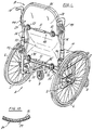
- a wheelchair A (Fig. 1) includes two side frames 2, each having a spindle 4 on which a large wheel 6 rotates. Fitted to the front of each side frame 2 is a smaller caster-type wheel 8. The two frames 2 are maintained generally parallel and a fixed distance apart by struts 10 which fold so that the side frames 2 will move together. This enables the wheelchair A to assume a more compact configuration suitable for storage or transport.
- Each side frame 2 has a horizontal member 12, and the horizontal members 12 of the two side frames 2 support a seat 14 which extends between them.
- Each side frame 2 at its rear also has a back post 16 which rises well above the horizontal member 12 and the wheel for the frame 2, and at its upper end turns rearwardly in the form of a handle 18.
- the back posts 16 of the two side frames 2 carry a backrest assembly B which, generally speaking, occupies the space between the two posts 16 where it extends well above the seat 14 and indeed up to and beyond the handles 18. Whereas, the seat 14 carries most of the user's weight, the backrest assembly B to a measure supports the user's back and certainly positions the back.
- the side frames 2, wheels 6 and 8, struts 10 and seat 14 are conventional. The invention resides in the backrest assembly B.
- the backrest assembly B (Figs. 2 & 3) includes a contoured backrest 24 having a top section 26 portion which is generally flat, a slightly concave upper back region 28 which is immediately below the top section 26, a forwardly bowed lumbar region 30 immediately below the concave region 28, and a generally flat lower end section 32 below the lumbar region 30.
- the upper margin of the top section 26 extends horizontally at the center of the top section 26 and then curves downwardly and merges with the side margins which lie along upper back region and lumbar region and as such are set inwardly from the back posts 16 of the two side frames 2.
- the side margins merge into a horizontal bottom margin which occupies most of the width of the bottom section 32 and is thus longer than horizontal portion of the top section 26.
- the upper back region 28 is slightly concave from side to side on its front surface.
- the lumbar region 30, while bowing forwardly and thus being convex on its forward surface is also concave from side to side (Fig. 10), so that side margins of the backrest 24 along the lumbar region project farther forwardly then the midsection of the lumbar region 30.
- the backrest 24 has a rigid backing plate 34 (Fig. 3) and a cushion 36 attached to backing plate 34.
- the backing plate may be formed from a sheet of generally rigid polymer such as ABS plastic.
- the cushion 36 may be a simple foam located over the forwardly presented face of the backing plate 34 or it may be a cellular cushion of the type manufactured and sold by ROHO, Inc., of Belleville, Illinois.
- the backrest assembly B includes upper and lower outriggers 40 and 42 (Fig. 2) which are adjustable in width (as will be explained hereinafter) and which extend transversely across the backrest 24, to which they are attached, and upper and lower brackets 44 and 46 which are mounted on the back posts 16 for the side frames 2 of the wheelchair A and engage the ends of the outriggers 40 and 42 to support the backrest 24 between the two back posts 16.
- the location of the ends of the outriggers 40 and 42 with respect the backrest 24 may be altered and likewise the location of the brackets 44 and 46 along the backposts 16 may be changed.
- the outriggers 40 and 42 serve as positioning members which control the vertical, horizontal and angular positions of the backrest 24.
- the upper outrigger 40 has a cross rod 50 divided into two sections 50a and 50b (Fig. 2) which extends transversely across the backrest 24 behind its upper back region 28.
- the two sections 50a and 50b are connected by a sleeve 51 and secured to the sleeve 51 by set screws 51a. This connection allows the cross rod 50 to be adjusted in length to accommodate wheel chairs of different widths.
- the cross rod 50 passes through two clamps 52 which are attached to the backing plate 34 of the backrest 24, and normally hold the outrigger 40 rigid with respect to the backrest 24. However, the clamps 52 may be released to relax their grips on the cross rod 50, and when released, the outrigger 40 will rotate relative to the backrest 24 and the upper brackets 44 as well.
- the backrest 24 to move relative to posts 16 and seat 14, in that the upper rods 42 engage the upper brackets 42 at ends 54 which are offset radially from the cross rod 50.
- the cross rod 50 extends slightly beyond the side margins of the backrest 24, and here the rod 50 turns radially in the form of positioning arms 56 which extend out to the offset ends 54.
- the two arms 56 extend in the same direction from the cross rod 50 and indeed are parallel.
- the ends 54 which derive from the arms 56 being turned outwardly, lie parallel to the cross rod 50 and in axial alignment, that is they are the same distance from the cross rod 50. If the width adjustment feature is not desired, the entire outrigger 40 may be formed from a single length of rod stock.
- Each clamp 52 includes (Fig. 4) an inside disk 60 and outside disk 62 which have opposed horizontal grooves 64 through which the cross rod 50 of the upper outrigger 40 extends. In depth, the grooves 64 are less than the radius of the cross rod 50, so that when the two disks 60 and 62 are clamped together, the cross rod 50 is captured tightly between the two and will not turn.
- the clamping is provided by two screws 66 which pass through the outer disk 62 and thread into the inner disk 60, one above the grooves 64 and the other below. When turned down, the screws 66 urge the outer disk 62 toward the inner disk 60 and thus prevent the outrigger 40 from rotating between the two disks 60 and 62.
- the inner disk 60 is attached to the backing plate 34 of the backrest 24 at the upper back region 28 of the plate 34, preferably by screws 68 which pass through the backing plate 34 and thread into the inner disk 60.
- the lower outrigger 42 is essentially the same as the upper outrigger 40 and as such has a cross rod 50 composed of sections 50a and 50b, offset ends 54 and connecting arms 56 located between the ends of the cross rod 50 and the offset ends 54 (Fig. 2).
- the two sections 50a and 50b are connected by a sleeve 51 and secured to the sleeve 51 by set screws 51a. This connection allows the cross rod 50 to be adjusted in length to accommodate wheel chairs of different widths.
- the cross rod 50 of the outrigger 42 extends horizontally behind the flat bottom section 32 of the backrest 24 and here the cross rod 50 is attached to the backing plate 34 of the backrest 24 at two lower clamps 70 which are identical to the upper clamps 52.
- each has inner and outer disks 60 and 62 provided with grooves 64 and screws 66 which urge the disks 40 and 42 together.
- the offset ends 54 of the lower outrigger 42 fit into the lower brackets 46.
- Each lower bracket 46 includes (Figs. 5 & 6) a block 72 having a concave forward face which matches the curvature of the back post 16 against which it fits.
- the block 72 near its lower end contains a short slot 74 that extends from side to side in the block 72 with its elongation perpendicular to the axis of the post 16.
- the slot 74 in turn contains a cross bar 76 which fits somewhat loosely so that it can move toward and away from the post 16.
- the cross bar 76 is slightly longer than the block 72 is wide, and has end caps 77 connected to its ends by reduced portions 77a.
- the cross bar 76 carries a strap 78 which passes around the front of the post 16.
- the strap 78 is provided with openings 79 which are slightly larger than end caps 77.
- the end caps 77 fit through the openings 79 to connect the strap 78 to the cross bar 76.
- the location of the cross bar 78 is under the control of a headed machine screw 82 which extends loosely through an opening 84 in the block 72 from its back face. Beyond the opening 84 the screw 82 threads into the cross bar 78 midway between the ends of the cross bar 78.
- the block 72 contains a vertical slot 86 which extends transversely and opens out of the upper end of the block 72.
- the slot 86 is large enough to accommodate one of the offset ends 54 of the lower outrigger 42 somewhat loosely and indeed receives that offset end 54.
- the lower brackets 46 by confining the offset ends 54 of the lower outrigger 42 in the vertical slots 86, serve to position lower end of the backrest 24, at least when the lower clamps 70 tightly grip the cross rod 50 of the outrigger 42 and prevents that rod from turning.
- the upper brackets 44 are somewhat similar to the lower brackets 46 (Figs. 7-9).
- each has a block 72 provided with a concave front surface that fits against the surface of one of the back posts 16.
- Each, near its lower end, also has a short slot 74 containing a crossbar 76 which serves to anchor the ends of a strap 78 that passes around the post 16, the strap having openings 79 slightly larger than the cross bar heads 77.
- the heads 77 are connected to the ends of the cross bar 76 by reduced portions 77a.
- a machine screw 82 extends loosely through an opening 84 in the block 72 from its back face. The screw 82, midway between the sides of the block 72, threads into the crossbar 76.
- the block 72 contains a vertical slot 86, which extends transversely and opens upwardly, and is furthermore large enough to receive one of the offset ends 54 on the upper outrigger rod 40.
- the slot 86 in the upper bracket 44 is shorter than the vertical slot 86 in the lower bracket 46 and furthermore is somewhat wider at its open top. Aside from that, the block 72 of the upper bracket 44 has another vertical slot 88 located midway between its sides, and this slot intersects the transverse slot 86.
- the block 72 of the upper bracket 44 contains a pivot pin 90 about which a latch 92 rotates between a locking or closed position and a release position. Urging the latch 92 to its closed position is a spring 94 which wraps around the pivot pin 90 and is to a large measure contained within the slot 88.
- the latch 92 When the latch 92 is in its closed position (Fig. 7), it blocks the upper end of the vertical slot 86, indeed, with an arcuate surface that conforms to the curvature of the offset end 54 of the upper outrigger 40. Enough space exists between the arcuate surface and the bottom of the slot 86 to accommodate the offset end 54, even as the latch 92 is moved to its release position. Of course, when the latch 92 is in its release position, it no longer blocks the vertical slot 86 and the offset end 54 may be lifted upwardly out of the slot 86. Indeed, as the latch 92 approaches its release position, another portion of the latch 92 enters the bottom of the slot 86 and actually pushes the offset end 54 of the upper outrigger 40 upwardly.
- the clamps 52 and 70, the outriggers 40 and 42 and the brackets 44 and 46 enable the backrest 24 to assume a multitude of positions, and by reason of the adjustment afforded by the clamps 52 and 70 and the brackets 44 and 46, a therapist should be able to position the backrest 24 to fit users of different sizes as well as users having different skeletal deformities.
- a therapist should be able to position the backrest 24 to fit users of different sizes as well as users having different skeletal deformities.
- the upper clamps 52 which is achieved simply by backing off the set screws 66, one can rotate the upper outrigger 40. Since the offset ends 54 of the outrigger 40 are confined to a fixed axis by the upper brackets 44, the rotation of the upper outrigger 40 moves the upper end of the backrest 24 forwardly and rearwardly as well as vertically.
- the cross rod 50 of the upper outrigger 40 serves as the end of a crank arm and the connected portion of the back rest 24 merely follows it.
- the lower brackets 46 while confining the offset ends 54 of the lower outriggers 42 horizontally, do not restrict it vertically, and hence the lower end of the backrest 24 is free to move to accommodate the vertical motion and rotation imparted to the upper outrigger 40. If the rotation elevates or depresses the upper end of the backrest 24 too much, the upper brackets 46 may be repositioned along the posts 16 by backing off the screws 82 that control their straps 78 and moving them to a new location.
- the location of the lower end of the backrest 24 is under the control of the lower outrigger 42, and it too, when turned, functions like a crank arm.
- its offset ends 54 not being confined vertically by the lower brackets 46, are free to rise and fall in the vertical slots 84 of those brackets.
- rotation of the lower outrigger 42 moves the lower end of the backrest 24 either forwardly or rearwardly.
- the backrest 24 does not detract from the capacity of the wheelchair A to fold into a highly compact configuration. Should one desire to collapse the wheelchair A, that individual fully depresses the latches 92, causing the latches 92 to push the offset ends 54 of the upper outriggers 40 upwardly in the slots 86 of the upper brackets 44. This, in effect, frees the offset ends 54 of the upper outriggers 40 from the upper brackets 44, so that the backrest 24 may be lifted upwardly. As this occurs, the offset ends 54 of the upper outriggers 40 come out of the vertical slots 86 in the upper bracket 44, whereas the offset ends 54 of the lower outriggers 42 come out of the vertical slots 86 in the lower brackets 46.
Landscapes
- Health & Medical Sciences (AREA)
- Life Sciences & Earth Sciences (AREA)
- Animal Behavior & Ethology (AREA)
- General Health & Medical Sciences (AREA)
- Public Health (AREA)
- Veterinary Medicine (AREA)
- Chair Legs, Seat Parts, And Backrests (AREA)
- Chairs For Special Purposes, Such As Reclining Chairs (AREA)
- Massaging Devices (AREA)
- Orthopedics, Nursing, And Contraception (AREA)
- Organic Low-Molecular-Weight Compounds And Preparation Thereof (AREA)
- Traffic Control Systems (AREA)
Abstract
Description
- This invention relates in general to seating and, more particularly, to a backrest assembly for wheelchairs.
- The typical wheelchair has a pair of side frames to which the wheels of the chair are attached and struts interposed between the frames for maintaining them apart and generally parallel. The struts for most wheelchairs collapse to enable the side frames to move together, thus allowing the wheelchair to assume a more compact configuration for storage or transport. Usually, the seat and backrest are nothing more than flexible slings that extend between the two frames. While the slings fold with the chair as it assumes its compact configuration, they fail to provide a truly optimum seating surface or back surface. Much of the problem resides in the seat, and special seat cushions are available to improve seating posture and reduce the incidence of pressure sores. Some individuals, particularly those whose muscles have atrophied or those who have spinal deformities, need better support than a traditional sling-type backrest can provide.
- Special contoured backs exist, but to a large measure they are custom made to accommodate the problems peculiar to individual users, and thus are very expensive. More universal backrests of a rigid character also exist, but they are difficult to adjust to accommodate the needs of individual users.
- A backrest assembly as defined in the precharacterizing portion of independent claim 1 is disclosed in US-A-4,898,425 and in US-A-5,062,677. The backrest assembly of US-A-4,898,425 can be attached at different positions and angles relative to the back posts of the chair by engaging studs at the upper portion of the backrest assembly into selected vertical notches formed in support plates fixed to the posts and by engaging pins at the lower portion of the backrest assembly into selected holes also formed in the support plates. The backrest assembly of US-A-5,062,677 is vertically adjustable on the wheel chair posts. For tilt adjustment spacers may be disposed between the chair posts and the backrest assembly.
- In GB-A-372 516 a backrest for chains and like seats is disclosed having a metal strip bolted to the backrest and pivotably attached to support means having linkages permitting universal adjusting movement about three axes between the backrest and the support means.
- The object of the present invention is to provide a backrest assembly for enhancing the posture and comfort of those confined to wheelchairs.
- To achieve this, there is provided in accordance with the invention a backrest assembly for a chair having upright posts which are spaced apart generally behind the seat of the chair and rise above that seat, said backrest assembly comprising a backrest located generally in the region between the posts so as to provide a surface for positioning the back of an individual who sits upon the seat; a first positioning member mounted on the backrest; and first connecting means on the posts for engaging the first positioning member; characterized in that the first positioning member is rotatable relative to the backrest and said posts about a generally horizontal axis and comprises an intermediate portion releasably clamped to the backrest and having end portions offset from said intermediate portion, said end portions being aligned and parallel to said intermediate portion, and said first connecting means engaging the end portions to permit said rotation of the first positioning member relative to the backrest and said posts when said first positioning member is released from said backrest.
- The positioning member and connecting means are such that the backrest may be moved to a multitude of positions - and in that sense the backrest is suited for use by a wide variety of individuals. In one embodiment the positioning member also is adjustable in width to accommodate chairs of different widths and to reduce the number of different sizes that must be kept in inventory. In another embodiment the backrest is easily removable from the wheelchair, so that the wheelchair may be folded to a compact configuration.
- In the accompanying drawings which form part of the specification and wherein like numerals and letters refer to like parts wherever they occur.
- Fig. 1 is a perspective view of a wheelchair provided with a backrest assembly constructed in accordance with and embodying the present invention;
- Fig. 2 is a rear elevational view of the backrest assembly attached to the backpost of a wheelchair.
- Fig. 3 is a sectional view of the backrest assembly taken along line 3-3 of Fig. 2.
- Fig. 4 is a sectional view of one of the outrigger clamps taken along line 4-4 of Fig. 2;
- Fig. 5 is a sectional view of one of the lower outrigger brackets taken along line 5-5 of Fig. 2;
- Fig. 6 is a sectional view of the lower outrigger bracket taken along line 6-6 of Fig. 5;
- Fig. 7 is a sectional view of one of the upper brackets taken along line 7-7 of Fig. 2;
- Fig. 8 is a top plan view of the upper outrigger bracket taken along line 8-8 of Fig. 7;
- Fig. 9 is a sectional view of the upper outrigger bracket taken along line 9-9 of Fig. 7, and;
- Fig. 10 is a sectional view taken along line 10-10 of Fig. 3 and showing the backrest forming part of the backrest assembly.
- Referring now to the drawings, a wheelchair A (Fig. 1) includes two
side frames 2, each having aspindle 4 on which alarge wheel 6 rotates. Fitted to the front of eachside frame 2 is a smaller caster-type wheel 8. The twoframes 2 are maintained generally parallel and a fixed distance apart bystruts 10 which fold so that theside frames 2 will move together. This enables the wheelchair A to assume a more compact configuration suitable for storage or transport. Eachside frame 2 has ahorizontal member 12, and thehorizontal members 12 of the twoside frames 2 support aseat 14 which extends between them. Eachside frame 2 at its rear also has aback post 16 which rises well above thehorizontal member 12 and the wheel for theframe 2, and at its upper end turns rearwardly in the form of ahandle 18. Theback posts 16 of the twoside frames 2 carry a backrest assembly B which, generally speaking, occupies the space between the twoposts 16 where it extends well above theseat 14 and indeed up to and beyond thehandles 18. Whereas, theseat 14 carries most of the user's weight, the backrest assembly B to a measure supports the user's back and certainly positions the back. Theside frames 2,wheels 6 and 8,struts 10 andseat 14 are conventional. The invention resides in the backrest assembly B. - The backrest assembly B (Figs. 2 & 3) includes a contoured
backrest 24 having atop section 26 portion which is generally flat, a slightly concaveupper back region 28 which is immediately below thetop section 26, a forwardly bowedlumbar region 30 immediately below theconcave region 28, and a generally flatlower end section 32 below thelumbar region 30. The upper margin of thetop section 26 extends horizontally at the center of thetop section 26 and then curves downwardly and merges with the side margins which lie along upper back region and lumbar region and as such are set inwardly from theback posts 16 of the twoside frames 2. At thebottom section 32 the side margins merge into a horizontal bottom margin which occupies most of the width of thebottom section 32 and is thus longer than horizontal portion of thetop section 26. Whereas thetop section 26 andbottom section 32 are to a large measure flat, theupper back region 28 is slightly concave from side to side on its front surface. Thelumbar region 30, while bowing forwardly and thus being convex on its forward surface is also concave from side to side (Fig. 10), so that side margins of thebackrest 24 along the lumbar region project farther forwardly then the midsection of thelumbar region 30. - The
backrest 24 has a rigid backing plate 34 (Fig. 3) and acushion 36 attached tobacking plate 34. The backing plate may be formed from a sheet of generally rigid polymer such as ABS plastic. Thecushion 36, on the other hand, may be a simple foam located over the forwardly presented face of thebacking plate 34 or it may be a cellular cushion of the type manufactured and sold by ROHO, Inc., of Belleville, Illinois. - In addition to the
backrest 24, the backrest assembly B includes upper andlower outriggers 40 and 42 (Fig. 2) which are adjustable in width (as will be explained hereinafter) and which extend transversely across thebackrest 24, to which they are attached, and upper andlower brackets back posts 16 for theside frames 2 of the wheelchair A and engage the ends of theoutriggers backrest 24 between the twoback posts 16. The location of the ends of theoutriggers backrest 24 may be altered and likewise the location of thebrackets backposts 16 may be changed. These adjustments permit thebackrest 24 to assume a multitude of positions with respect to theseat 14, and thus thebackrest 24 can meet the requirements of many different users and many different types of chairs. In short, theoutriggers backrest 24. - The
upper outrigger 40 has across rod 50 divided into twosections 50a and 50b (Fig. 2) which extends transversely across thebackrest 24 behind itsupper back region 28. The twosections 50a and 50b are connected by asleeve 51 and secured to thesleeve 51 by set screws 51a. This connection allows thecross rod 50 to be adjusted in length to accommodate wheel chairs of different widths. Thecross rod 50 passes through twoclamps 52 which are attached to thebacking plate 34 of thebackrest 24, and normally hold theoutrigger 40 rigid with respect to thebackrest 24. However, theclamps 52 may be released to relax their grips on thecross rod 50, and when released, theoutrigger 40 will rotate relative to thebackrest 24 and theupper brackets 44 as well. This permits thebackrest 24 to move relative toposts 16 andseat 14, in that theupper rods 42 engage theupper brackets 42 atends 54 which are offset radially from thecross rod 50. More specifically, thecross rod 50 extends slightly beyond the side margins of thebackrest 24, and here therod 50 turns radially in the form of positioningarms 56 which extend out to theoffset ends 54. The twoarms 56 extend in the same direction from thecross rod 50 and indeed are parallel. Theends 54, which derive from thearms 56 being turned outwardly, lie parallel to thecross rod 50 and in axial alignment, that is they are the same distance from thecross rod 50. If the width adjustment feature is not desired, theentire outrigger 40 may be formed from a single length of rod stock. - Each
clamp 52 includes (Fig. 4) aninside disk 60 and outsidedisk 62 which have opposedhorizontal grooves 64 through which thecross rod 50 of theupper outrigger 40 extends. In depth, thegrooves 64 are less than the radius of thecross rod 50, so that when the twodisks cross rod 50 is captured tightly between the two and will not turn. The clamping is provided by twoscrews 66 which pass through theouter disk 62 and thread into theinner disk 60, one above thegrooves 64 and the other below. When turned down, thescrews 66 urge theouter disk 62 toward theinner disk 60 and thus prevent theoutrigger 40 from rotating between the twodisks inner disk 60 is attached to thebacking plate 34 of thebackrest 24 at theupper back region 28 of theplate 34, preferably byscrews 68 which pass through thebacking plate 34 and thread into theinner disk 60. - The
lower outrigger 42 is essentially the same as theupper outrigger 40 and as such has across rod 50 composed ofsections 50a and 50b, offset ends 54 and connectingarms 56 located between the ends of thecross rod 50 and the offset ends 54 (Fig. 2). The twosections 50a and 50b are connected by asleeve 51 and secured to thesleeve 51 by set screws 51a. This connection allows thecross rod 50 to be adjusted in length to accommodate wheel chairs of different widths. Thecross rod 50 of theoutrigger 42 extends horizontally behind theflat bottom section 32 of thebackrest 24 and here thecross rod 50 is attached to thebacking plate 34 of thebackrest 24 at twolower clamps 70 which are identical to theupper clamps 52. As such, each has inner andouter disks grooves 64 and screws 66 which urge thedisks lower outrigger 42 fit into thelower brackets 46. - Each
lower bracket 46 includes (Figs. 5 & 6) ablock 72 having a concave forward face which matches the curvature of theback post 16 against which it fits. Theblock 72 near its lower end contains ashort slot 74 that extends from side to side in theblock 72 with its elongation perpendicular to the axis of thepost 16. Theslot 74 in turn contains across bar 76 which fits somewhat loosely so that it can move toward and away from thepost 16. Thecross bar 76 is slightly longer than theblock 72 is wide, and hasend caps 77 connected to its ends by reducedportions 77a. Thecross bar 76 carries astrap 78 which passes around the front of thepost 16. At its ends, thestrap 78 is provided withopenings 79 which are slightly larger thanend caps 77. The end caps 77 fit through theopenings 79 to connect thestrap 78 to thecross bar 76. When thebar 76 is at the front of itsslot 74, thestrap 78 fits rather loosely around thepost 16 and thebracket 46 may move upwardly and downwardly on thepost 16. However, the location of thecross bar 78 is under the control of a headedmachine screw 82 which extends loosely through anopening 84 in theblock 72 from its back face. Beyond theopening 84 thescrew 82 threads into thecross bar 78 midway between the ends of thecross bar 78. When the head of thescrew 82 is turned down against the back face of theblock 72, thecross bar 78 moves rearwardly and draws thestrap 78 tightly around thepost 16. This secures theblock 72 firmly against thepost 16. In addition, theblock 72 contains avertical slot 86 which extends transversely and opens out of the upper end of theblock 72. Theslot 86 is large enough to accommodate one of the offset ends 54 of thelower outrigger 42 somewhat loosely and indeed receives that offsetend 54. Thus, thelower brackets 46, by confining the offset ends 54 of thelower outrigger 42 in thevertical slots 86, serve to position lower end of thebackrest 24, at least when the lower clamps 70 tightly grip thecross rod 50 of theoutrigger 42 and prevents that rod from turning. - The
upper brackets 44 are somewhat similar to the lower brackets 46 (Figs. 7-9). In this regard, each has ablock 72 provided with a concave front surface that fits against the surface of one of the back posts 16. Each, near its lower end, also has ashort slot 74 containing acrossbar 76 which serves to anchor the ends of astrap 78 that passes around thepost 16, thestrap having openings 79 slightly larger than the cross bar heads 77. Theheads 77 are connected to the ends of thecross bar 76 by reducedportions 77a. Amachine screw 82 extends loosely through anopening 84 in theblock 72 from its back face. Thescrew 82, midway between the sides of theblock 72, threads into thecrossbar 76. Thus, when the head of thescrew 82 is turned downwardly against the back face of theblock 72, thecross bar 78 is drawn rearwardly until thestrap 78 tightly grips thepost 16. In addition, theblock 72 contains avertical slot 86, which extends transversely and opens upwardly, and is furthermore large enough to receive one of the offset ends 54 on theupper outrigger rod 40. However, theslot 86 in theupper bracket 44 is shorter than thevertical slot 86 in thelower bracket 46 and furthermore is somewhat wider at its open top. Aside from that, theblock 72 of theupper bracket 44 has anothervertical slot 88 located midway between its sides, and this slot intersects thetransverse slot 86. Between the bottom of thetransverse slot 86 and theshort slot 74 in which thecross bar 76 is contained, theblock 72 of theupper bracket 44 contains apivot pin 90 about which alatch 92 rotates between a locking or closed position and a release position. Urging thelatch 92 to its closed position is aspring 94 which wraps around thepivot pin 90 and is to a large measure contained within theslot 88. - When the
latch 92 is in its closed position (Fig. 7), it blocks the upper end of thevertical slot 86, indeed, with an arcuate surface that conforms to the curvature of the offsetend 54 of theupper outrigger 40. Enough space exists between the arcuate surface and the bottom of theslot 86 to accommodate the offsetend 54, even as thelatch 92 is moved to its release position. Of course, when thelatch 92 is in its release position, it no longer blocks thevertical slot 86 and the offsetend 54 may be lifted upwardly out of theslot 86. Indeed, as thelatch 92 approaches its release position, another portion of thelatch 92 enters the bottom of theslot 86 and actually pushes the offsetend 54 of theupper outrigger 40 upwardly. - The
clamps outriggers brackets backrest 24 to assume a multitude of positions, and by reason of the adjustment afforded by theclamps brackets backrest 24 to fit users of different sizes as well as users having different skeletal deformities. By releasing theupper clamps 52, which is achieved simply by backing off theset screws 66, one can rotate theupper outrigger 40. Since the offset ends 54 of theoutrigger 40 are confined to a fixed axis by theupper brackets 44, the rotation of theupper outrigger 40 moves the upper end of thebackrest 24 forwardly and rearwardly as well as vertically. In effect, thecross rod 50 of theupper outrigger 40 serves as the end of a crank arm and the connected portion of theback rest 24 merely follows it. - The
lower brackets 46, while confining the offset ends 54 of thelower outriggers 42 horizontally, do not restrict it vertically, and hence the lower end of thebackrest 24 is free to move to accommodate the vertical motion and rotation imparted to theupper outrigger 40. If the rotation elevates or depresses the upper end of thebackrest 24 too much, theupper brackets 46 may be repositioned along theposts 16 by backing off thescrews 82 that control theirstraps 78 and moving them to a new location. - On the other hand, the location of the lower end of the
backrest 24 is under the control of thelower outrigger 42, and it too, when turned, functions like a crank arm. However, its offset ends 54, not being confined vertically by thelower brackets 46, are free to rise and fall in thevertical slots 84 of those brackets. Hence, rotation of thelower outrigger 42 moves the lower end of thebackrest 24 either forwardly or rearwardly. Should the adjustments provided by rotation of either one of theoutriggers lower outrigger 42 above thelower brackets 46, those brackets may be raised to again recapture the offset ends 54 of thelower outrigger 42, simply by loosening thescrews 82 and moving thebrackets 46 upwardly to the desired location, whereupon thescrews 82 are again tightened. The same holds true if the rotation of eitheroutrigger lower outriggers 42 into the bottoms of theslots 86 for thelower brackets 46. - The
backrest 24 does not detract from the capacity of the wheelchair A to fold into a highly compact configuration. Should one desire to collapse the wheelchair A, that individual fully depresses thelatches 92, causing thelatches 92 to push the offset ends 54 of theupper outriggers 40 upwardly in theslots 86 of theupper brackets 44. This, in effect, frees the offset ends 54 of theupper outriggers 40 from theupper brackets 44, so that thebackrest 24 may be lifted upwardly. As this occurs, the offset ends 54 of theupper outriggers 40 come out of thevertical slots 86 in theupper bracket 44, whereas the offset ends 54 of thelower outriggers 42 come out of thevertical slots 86 in thelower brackets 46.
Claims (14)
- A backrest assembly for a chair (A) having upright posts (16) which are spaced apart generally behind the seat (14) of the chair (A) and rise above that seat (14), said backrest assembly (B) comprising: a backrest (24) located generally in the region between the posts (16) so as to provide a surface for positioning the back of an individual who sits upon the seat (14); a first positioning member (40) mounted on the backrest (24); and first connecting means (44) on the posts (16) for engaging the first positioning member (40); characterized in that the first positioning member (40) is rotatable relative to the backrest (24) and said posts (16) about a generally horizontal axis and comprises an intermediate portion releasably clamped to the backrest (24) and having end portions (54) offset from said intermediate portion, said end portions (54) being aligned and parallel to said intermediate portion, and said first connecting means (44) engaging the end portions (54) to permit said rotation of the first positioning member (40) relative to the backrest (24) and said posts (16) when said first positioning member is released from said backrest (24).
- A backrest assembly according to claim 1, characterized in that a second positioning member (42) is mounted on the backrest (24), said second positioning member (42) being rotatable relative to the backrest (24) and said posts (16) about a generally horizontal axis and comprising an intermediate portion releasably clamped to the backrest (24) and having end portions (54) offset from said intermediate portion, said end portions (54) being aligned and parallel to said intermediate portion, and second connecting means (46) on the posts (16) for engaging the end portions (54) of the second positioning member (42) to permit said rotation of the second positioning member (42) relative to the backrest (24) and said posts (16) when said second positioning member (42) is released from said backrest (24).
- A backrest assembly according to claim 2, characterized by comprising clamps (52, 70) on the backrest (24) for enabling the positioning members (40, 42) to rotate relative to the backrest (24) when in a release condition and for preventing rotating of the positioning members (40, 42) when in a clamping condition, whereby the positioning members (40, 42) may be rotated to a desired position and then secured against rotation.
- A backrest assembly according to claim 2, characterized in that the backrest (24) bows forwardly between the first and second positioning members (40, 42).
- A backrest assembly according to claim 2, characterized in that the connecting means (44, 46) have slots (86) which receive the offset end portions (54) of the positioning members (40, 42).
- A backrest assembly according to claim 5, characterized in that the slots (86) of the connecting means (44, 46) have open ends, and the open ends are presented upwardly.
- A backrest assembly according to claim 6, characterized in that at least one (44) of the connecting means (44, 46) has a releasable latch (92) which prevents the offset end portion (54) that fits within the slot (86) at that connecting means (44) from being withdrawn upwardly unless released.
- A backrest assembly according to claim 7, characterized in that the connecting means (44, 46) is movable to different positions along the posts (16).
- A backrest assembly according to claim 7, characterized in that each connecting means (44, 46) comprises a block (72) located along one of the posts (16) and containing the upwardly opening slot (86) for receiving one of the offset end portions (54), a strap (78) which extends around the post (16), and means (76, 82) for drawing the strap (78) back toward the block (72) so as to urge the block (72) tightly against the post (16) along which it is located.
- A backrest assembly according to claim 3, characterized in that each positioning member (40, 42) is a rod having a cross portion (50) defining said intermediate portion and extending horizontally across the backrest (24), radially directed arms (56) located beyond the backrest (24), and the offset end portions (54) which are located at the ends of the arms (56) where they are axially aligned with each other and are parallel to the cross portion (50).
- A backrest assembly according to claim 4, characterized in that each clamp (52, 70) comprises inner and outer clamp elements (60, 62) having opposed grooves (64) which receive the intermediate portion of one of the positioning members (40, 42), and means (66) for urging the outer clamp element (62) toward the inner clamp element (60), and that the inner clamp element (60) is attached to the backrest (24).
- A backrest assembly according to claim 11, characterized in that the means for urging the clamp elements (60, 62) together are screws (66), there being one screw (66) located above the grooves (64) of the clamp elements (60, 62) and another located below the grooves (64).
- The backrest assembly of claim 2, characterized in that the first and second positioning members (40, 42) are laterally adjustable to accommodate backrests (24) of different widths.
- The backrest assembly of claim 13, characterized in that said positioning members (40, 42) each include a cross rod (50) formed in two sections (50a, 50b), a sleeve (51) connecting said sections (50a, 50b), and means (51a) to fix the locations of said rod sections (50a, 50b) with respect to said sleeve (51).
Applications Claiming Priority (3)
| Application Number | Priority Date | Filing Date | Title |
|---|---|---|---|
| US07/663,098 US5364162A (en) | 1991-03-01 | 1991-03-01 | Backrest assembly for a wheelchair |
| US663098 | 1991-03-01 | ||
| PCT/US1992/001279 WO1992015228A1 (en) | 1991-03-01 | 1992-02-18 | Backrest assembly for a wheelchair |
Publications (3)
| Publication Number | Publication Date |
|---|---|
| EP0529063A1 EP0529063A1 (en) | 1993-03-03 |
| EP0529063A4 EP0529063A4 (en) | 1993-07-28 |
| EP0529063B1 true EP0529063B1 (en) | 1997-01-15 |
Family
ID=24660465
Family Applications (1)
| Application Number | Title | Priority Date | Filing Date |
|---|---|---|---|
| EP92908696A Expired - Lifetime EP0529063B1 (en) | 1991-03-01 | 1992-02-18 | Backrest assembly for a wheelchair |
Country Status (9)
| Country | Link |
|---|---|
| US (1) | US5364162A (en) |
| EP (1) | EP0529063B1 (en) |
| JP (1) | JPH05506599A (en) |
| AT (1) | ATE147600T1 (en) |
| CA (1) | CA2081775A1 (en) |
| DE (1) | DE69216711T2 (en) |
| DK (1) | DK0529063T3 (en) |
| ES (1) | ES2097321T3 (en) |
| WO (1) | WO1992015228A1 (en) |
Families Citing this family (61)
| Publication number | Priority date | Publication date | Assignee | Title |
|---|---|---|---|---|
| CA2106361C (en) * | 1993-09-16 | 2000-11-28 | Nenad B. Medjedovic | Wheelchair backrest |
| US6056712A (en) * | 1995-10-31 | 2000-05-02 | Grim; Tracy E. | Multi-functional orthosis for the foot, heel, ankle and lower leg |
| US5971417A (en) * | 1996-11-12 | 1999-10-26 | Sunrise Medical Hhg Inc. | Wheelchair with pivotal back rest |
| DE29706398U1 (en) * | 1997-04-10 | 1997-05-22 | Megaplast S.A., Bilbao | Backrest for backrests, in particular for motor vehicle seats |
| USD407353S (en) | 1997-10-06 | 1999-03-30 | Roho, Inc. | Back support for a wheelchair |
| USD413085S (en) | 1997-10-06 | 1999-08-24 | Roho, Inc. | Back support pad assembly for a wheelchair |
| USD412685S (en) | 1997-10-06 | 1999-08-10 | Roho, Inc. | Back support pad assembly for a wheelchair |
| USD408767S (en) | 1997-10-06 | 1999-04-27 | Roho, Inc. | Back support for a wheelchair |
| USD413841S (en) * | 1997-10-06 | 1999-09-14 | Roho, Inc. | Back support pad assembly for a wheelchair |
| US6095611A (en) * | 1997-10-07 | 2000-08-01 | Roho, Inc. | Modular backrest system for a wheelchair |
| US5909923A (en) | 1997-10-24 | 1999-06-08 | Steelcase Inc. | Chair with novel pivot mounts and method of assembly |
| US6007150A (en) | 1998-03-08 | 1999-12-28 | Milsco Manufacturing Company | Motorcycle seat with adjustable backrest |
| US6186594B1 (en) | 1998-04-07 | 2001-02-13 | Corporation De L'ecole Polytechnique | Flexible contour wheelchair backrest |
| AUPP532398A0 (en) * | 1998-08-18 | 1998-09-10 | King, David Russell | Adjustable back furniture |
| US6257664B1 (en) | 1998-11-16 | 2001-07-10 | Invacare Corporation | Multiple adjustable back assembly for use with wheelchair |
| US6519797B1 (en) | 1999-08-10 | 2003-02-18 | Dynamic Contours Llc | Self adjusting, contouring cushioning system |
| US6941602B2 (en) | 1999-08-10 | 2005-09-13 | Dynamic Contours, Llc | Self adjusting, contouring cushioning system |
| US6460933B1 (en) * | 2000-02-28 | 2002-10-08 | Invacare Corporation | Multiply adjustable low back support assembly for a wheelchair |
| US6487739B1 (en) | 2000-06-01 | 2002-12-03 | Crown Therapeutics, Inc. | Moisture drying mattress with separate zone controls |
| US6474743B1 (en) * | 2000-09-18 | 2002-11-05 | Crown Therapeutics, Inc. | Wheelchair back support assembly |
| US6688693B2 (en) * | 2000-10-02 | 2004-02-10 | Sunrise Medical Hhg Inc. | Seat back assembly |
| AU2002220143A1 (en) * | 2000-11-01 | 2002-05-15 | Cascade Designs, Inc. | Adjustable quick release seatback system particularly for use with wheelchairs |
| WO2002058615A2 (en) * | 2001-01-25 | 2002-08-01 | Hill-Rom Services, Inc. | Hydraulic actuator apparatus for a surgical table |
| RU2192661C1 (en) * | 2001-03-01 | 2002-11-10 | Открытое акционерное общество "Компания Славич" | Multipurpose photopolymerizing composition of soldering mask for printed circuit boards with raised operating characteristic |
| US6659563B2 (en) * | 2001-10-18 | 2003-12-09 | Invacare Corporation | Adjustable quick release frameless back support for a wheelchair |
| US6913318B2 (en) | 2002-12-03 | 2005-07-05 | Pride Mobility Products Corporation | Adjustable seat support for a wheelchair |
| US7434282B2 (en) | 2003-05-29 | 2008-10-14 | Star Cushion Products, Inc. | Cellular cushions and methods of fabricating |
| US7883478B2 (en) * | 2004-04-30 | 2011-02-08 | Hill-Rom Services, Inc. | Patient support having real time pressure control |
| US7469436B2 (en) | 2004-04-30 | 2008-12-30 | Hill-Rom Services, Inc. | Pressure relief surface |
| US20070235036A1 (en) * | 2004-04-30 | 2007-10-11 | Bobey John A | Patient support |
| US7557718B2 (en) * | 2004-04-30 | 2009-07-07 | Hill-Rom Services, Inc. | Lack of patient movement monitor and method |
| US7458637B2 (en) | 2004-06-10 | 2008-12-02 | Steelcase Inc. | Back construction with flexible lumbar |
| US7237841B2 (en) | 2004-06-10 | 2007-07-03 | Steelcase Development Corporation | Back construction with flexible lumbar |
| US7854481B2 (en) * | 2004-06-15 | 2010-12-21 | Star Cushion Products, Inc. | Methods and apparatus for assembling a wheel chair |
| US7104610B2 (en) * | 2004-10-08 | 2006-09-12 | Marken International, Inc. | Apparatus for mounting a wheelchair back |
| US7147282B2 (en) * | 2004-11-08 | 2006-12-12 | Kimball International, Inc. | Chair with backrest depth adjustment mechanism |
| JP4800633B2 (en) * | 2005-02-09 | 2011-10-26 | 株式会社イトーキ | Chair |
| CA2501430A1 (en) * | 2005-03-18 | 2006-09-18 | Broda Enterprises Inc. | Backrest for bariatric chair |
| CA2501419A1 (en) * | 2005-03-18 | 2006-09-18 | Broda Enterprises Inc. | Armrest for bariatric chair |
| JP5231222B2 (en) | 2005-07-08 | 2013-07-10 | ヒル−ロム サービシーズ,インコーポレイティド | Patient support control unit |
| AU2006269277B2 (en) | 2005-07-08 | 2012-02-16 | Hill-Rom, Inc. | Patient support |
| AU2006268287B2 (en) | 2005-07-08 | 2012-03-08 | Hill-Rom Services, Inc. | Pressure control for a hospital bed |
| US7350251B2 (en) * | 2005-07-12 | 2008-04-01 | Kevin Gerard Fraser | Cellular cushion |
| US8745788B2 (en) | 2005-07-26 | 2014-06-10 | Hill-Rom Services. Inc. | System and method for controlling an air mattress |
| US20070108829A1 (en) * | 2005-11-15 | 2007-05-17 | Saint Louis University | Swing away removable solid wheelchair seat back |
| US7896438B2 (en) * | 2006-09-29 | 2011-03-01 | Sunrise Medical Hhg, Inc. | Shapeable wheelchair seatback assembly |
| EP1974707B1 (en) | 2007-03-08 | 2011-07-20 | Sunrise Medical HHG Inc. | Wheelchair seatback with two-point mounting hardware |
| CA2694291A1 (en) * | 2007-07-25 | 2009-01-29 | Roho, Inc. | Supportive back overlay for wheelchair back |
| US7717512B2 (en) * | 2007-10-23 | 2010-05-18 | Toyota Boshoku Kabushiki Kaisha | Seat backs for vehicular seats |
| DE102007060075B4 (en) * | 2007-12-13 | 2025-09-11 | Volkswagen Ag | Contour-adaptive vehicle seat |
| EP2317964A2 (en) | 2008-08-07 | 2011-05-11 | Roho, Inc. | Wheelchair back mounting assembly |
| AU2011216161B2 (en) * | 2010-02-11 | 2016-08-25 | Roho, Inc. | Wheelchair back mounting assembly |
| US8567863B2 (en) | 2011-03-02 | 2013-10-29 | Aspen Seating, Llc | Back support, orientation mechanism and method |
| US8973186B2 (en) | 2011-12-08 | 2015-03-10 | Hill-Rom Services, Inc. | Optimization of the operation of a patient-support apparatus based on patient response |
| US9468307B2 (en) | 2012-09-05 | 2016-10-18 | Stryker Corporation | Inflatable mattress and control methods |
| US8517469B1 (en) | 2012-09-06 | 2013-08-27 | Aspen Seating, Llc | Three-axis adjustable back support assembly and method |
| EP2913038B1 (en) * | 2014-03-01 | 2017-05-10 | Sunrise Medical GmbH | Wheelchair backrest having position adjustment |
| US10194745B2 (en) | 2015-11-06 | 2019-02-05 | The Comfort Companies, Llc | Assembly for mounting and independent multi-direction adjustment of a seat back |
| US12161601B2 (en) | 2018-02-20 | 2024-12-10 | Angel Rodriguez-Cruz | Wheeleta |
| US12090102B2 (en) * | 2020-04-03 | 2024-09-17 | Sunrise Medical (Us) Llc | Wheelchair back support adjustment system with central spherical joint |
| CN116570436B (en) * | 2023-05-31 | 2024-01-23 | 佛山达浩医疗科技有限公司 | Shifting vehicle |
Family Cites Families (6)
| Publication number | Priority date | Publication date | Assignee | Title |
|---|---|---|---|---|
| GB320732A (en) * | 1928-09-13 | 1929-10-24 | Ludwig Holland Letz | A device for taking up the wear on an anti-friction bearing |
| GB372516A (en) * | 1931-04-13 | 1932-05-12 | Leabank Mfg Company Ltd | Improvements relating to back-rests for chairs and like seats |
| US3203732A (en) * | 1963-01-28 | 1965-08-31 | William A Hoffman | Chair having adjustable back and seat |
| CA2002031C (en) * | 1988-11-16 | 1993-03-23 | Eric C. Jay | Wheelchair back system |
| US4898425A (en) * | 1989-06-28 | 1990-02-06 | Mundy Philip C | Seat belt kit for wheelchairs |
| US5067677A (en) * | 1990-12-14 | 1991-11-26 | Edward Miceli | Wire harness |
-
1991
- 1991-03-01 US US07/663,098 patent/US5364162A/en not_active Expired - Fee Related
-
1992
- 1992-02-18 AT AT92908696T patent/ATE147600T1/en not_active IP Right Cessation
- 1992-02-18 ES ES92908696T patent/ES2097321T3/en not_active Expired - Lifetime
- 1992-02-18 DK DK92908696.5T patent/DK0529063T3/en active
- 1992-02-18 JP JP92507816A patent/JPH05506599A/en active Pending
- 1992-02-18 CA CA002081775A patent/CA2081775A1/en not_active Abandoned
- 1992-02-18 WO PCT/US1992/001279 patent/WO1992015228A1/en not_active Ceased
- 1992-02-18 DE DE69216711T patent/DE69216711T2/en not_active Expired - Fee Related
- 1992-02-18 EP EP92908696A patent/EP0529063B1/en not_active Expired - Lifetime
Also Published As
| Publication number | Publication date |
|---|---|
| ATE147600T1 (en) | 1997-02-15 |
| DK0529063T3 (en) | 1997-06-30 |
| ES2097321T3 (en) | 1997-04-01 |
| US5364162A (en) | 1994-11-15 |
| JPH05506599A (en) | 1993-09-30 |
| CA2081775A1 (en) | 1992-09-02 |
| WO1992015228A1 (en) | 1992-09-17 |
| EP0529063A4 (en) | 1993-07-28 |
| DE69216711T2 (en) | 1997-08-07 |
| DE69216711D1 (en) | 1997-02-27 |
| EP0529063A1 (en) | 1993-03-03 |
Similar Documents
| Publication | Publication Date | Title |
|---|---|---|
| US5364162A (en) | Backrest assembly for a wheelchair | |
| US5556168A (en) | Wheelchair back system | |
| US6186594B1 (en) | Flexible contour wheelchair backrest | |
| US4981325A (en) | Posture support with multi-planar adjustment | |
| US6659563B2 (en) | Adjustable quick release frameless back support for a wheelchair | |
| US4793655A (en) | Multi-position convertible therapeutic chair | |
| US6460933B1 (en) | Multiply adjustable low back support assembly for a wheelchair | |
| US5228747A (en) | Seating system | |
| CA1291940C (en) | Knee-action chair control | |
| US6206393B1 (en) | Constant center of gravity tilt seat of a wheelchair | |
| US6276704B1 (en) | Adjustable wheelchair having a tilting and reclining seat | |
| US5427436A (en) | Adjustable headrest | |
| US4617919A (en) | Wheelchair with posture supports | |
| JP4740521B2 (en) | Adjustable quick release seat back system especially suitable for wheelchairs | |
| JP2001507613A (en) | Modular backrest complex for wheelchairs | |
| US20030006578A1 (en) | Size-adjustable laterally-folding tilting-frame wheelchair | |
| US5172925A (en) | Mobile prone stander with positioning chair | |
| JP7739343B2 (en) | Head support assembly and head support unit | |
| US5607202A (en) | Collapsible back support | |
| EP0960614A2 (en) | Fittings and chair for use with such fittings | |
| AU742801B2 (en) | Constant center of gravity tilt seat of a wheelchair | |
| CA2233928C (en) | Flexible contour wheelchair backrest | |
| US5335972A (en) | Reclining chair | |
| CN221489501U (en) | Chair and backrest assembly thereof | |
| CA1241901A (en) | Wheelchair |
Legal Events
| Date | Code | Title | Description |
|---|---|---|---|
| PUAI | Public reference made under article 153(3) epc to a published international application that has entered the european phase |
Free format text: ORIGINAL CODE: 0009012 |
|
| AK | Designated contracting states |
Kind code of ref document: A1 Designated state(s): AT BE CH DE DK ES FR GB GR IT LI LU MC NL SE |
|
| 17P | Request for examination filed |
Effective date: 19930201 |
|
| A4 | Supplementary search report drawn up and despatched |
Effective date: 19930608 |
|
| AK | Designated contracting states |
Kind code of ref document: A4 Designated state(s): AT BE CH DE DK ES FR GB GR IT LI LU MC NL SE |
|
| 17Q | First examination report despatched |
Effective date: 19950612 |
|
| GRAG | Despatch of communication of intention to grant |
Free format text: ORIGINAL CODE: EPIDOS AGRA |
|
| GRAH | Despatch of communication of intention to grant a patent |
Free format text: ORIGINAL CODE: EPIDOS IGRA |
|
| GRAH | Despatch of communication of intention to grant a patent |
Free format text: ORIGINAL CODE: EPIDOS IGRA |
|
| GRAA | (expected) grant |
Free format text: ORIGINAL CODE: 0009210 |
|
| AK | Designated contracting states |
Kind code of ref document: B1 Designated state(s): AT BE CH DE DK ES FR GB GR IT LI LU MC NL SE |
|
| PG25 | Lapsed in a contracting state [announced via postgrant information from national office to epo] |
Ref country code: GR Free format text: LAPSE BECAUSE OF FAILURE TO SUBMIT A TRANSLATION OF THE DESCRIPTION OR TO PAY THE FEE WITHIN THE PRESCRIBED TIME-LIMIT Effective date: 19970115 |
|
| REF | Corresponds to: |
Ref document number: 147600 Country of ref document: AT Date of ref document: 19970215 Kind code of ref document: T |
|
| REG | Reference to a national code |
Ref country code: CH Ref legal event code: EP |
|
| REF | Corresponds to: |
Ref document number: 69216711 Country of ref document: DE Date of ref document: 19970227 |
|
| REG | Reference to a national code |
Ref country code: ES Ref legal event code: FG2A Ref document number: 2097321 Country of ref document: ES Kind code of ref document: T3 |
|
| ITF | It: translation for a ep patent filed | ||
| ET | Fr: translation filed | ||
| REG | Reference to a national code |
Ref country code: DK Ref legal event code: T3 |
|
| PLBE | No opposition filed within time limit |
Free format text: ORIGINAL CODE: 0009261 |
|
| 26N | No opposition filed | ||
| PGFP | Annual fee paid to national office [announced via postgrant information from national office to epo] |
Ref country code: AT Payment date: 19980121 Year of fee payment: 7 |
|
| PGFP | Annual fee paid to national office [announced via postgrant information from national office to epo] |
Ref country code: CH Payment date: 19980203 Year of fee payment: 7 |
|
| PGFP | Annual fee paid to national office [announced via postgrant information from national office to epo] |
Ref country code: GB Payment date: 19990115 Year of fee payment: 8 Ref country code: FR Payment date: 19990115 Year of fee payment: 8 |
|
| PGFP | Annual fee paid to national office [announced via postgrant information from national office to epo] |
Ref country code: NL Payment date: 19990119 Year of fee payment: 8 Ref country code: MC Payment date: 19990119 Year of fee payment: 8 |
|
| PGFP | Annual fee paid to national office [announced via postgrant information from national office to epo] |
Ref country code: DE Payment date: 19990122 Year of fee payment: 8 |
|
| PGFP | Annual fee paid to national office [announced via postgrant information from national office to epo] |
Ref country code: SE Payment date: 19990125 Year of fee payment: 8 Ref country code: DK Payment date: 19990125 Year of fee payment: 8 |
|
| PGFP | Annual fee paid to national office [announced via postgrant information from national office to epo] |
Ref country code: LU Payment date: 19990126 Year of fee payment: 8 |
|
| PGFP | Annual fee paid to national office [announced via postgrant information from national office to epo] |
Ref country code: BE Payment date: 19990201 Year of fee payment: 8 |
|
| PG25 | Lapsed in a contracting state [announced via postgrant information from national office to epo] |
Ref country code: AT Free format text: LAPSE BECAUSE OF NON-PAYMENT OF DUE FEES Effective date: 19990218 |
|
| PGFP | Annual fee paid to national office [announced via postgrant information from national office to epo] |
Ref country code: ES Payment date: 19990218 Year of fee payment: 8 |
|
| PG25 | Lapsed in a contracting state [announced via postgrant information from national office to epo] |
Ref country code: LI Free format text: LAPSE BECAUSE OF NON-PAYMENT OF DUE FEES Effective date: 19990228 Ref country code: CH Free format text: LAPSE BECAUSE OF NON-PAYMENT OF DUE FEES Effective date: 19990228 |
|
| PG25 | Lapsed in a contracting state [announced via postgrant information from national office to epo] |
Ref country code: NL Free format text: LAPSE BECAUSE OF NON-PAYMENT OF DUE FEES Effective date: 19990901 |
|
| REG | Reference to a national code |
Ref country code: CH Ref legal event code: PL |
|
| PG25 | Lapsed in a contracting state [announced via postgrant information from national office to epo] |
Ref country code: FR Free format text: LAPSE BECAUSE OF NON-PAYMENT OF DUE FEES Effective date: 19991029 |
|
| REG | Reference to a national code |
Ref country code: FR Ref legal event code: ST |
|
| PG25 | Lapsed in a contracting state [announced via postgrant information from national office to epo] |
Ref country code: LU Free format text: LAPSE BECAUSE OF NON-PAYMENT OF DUE FEES Effective date: 20000218 Ref country code: GB Free format text: LAPSE BECAUSE OF NON-PAYMENT OF DUE FEES Effective date: 20000218 Ref country code: DK Free format text: LAPSE BECAUSE OF NON-PAYMENT OF DUE FEES Effective date: 20000218 |
|
| PG25 | Lapsed in a contracting state [announced via postgrant information from national office to epo] |
Ref country code: SE Free format text: LAPSE BECAUSE OF NON-PAYMENT OF DUE FEES Effective date: 20000219 Ref country code: ES Free format text: LAPSE BECAUSE OF NON-PAYMENT OF DUE FEES Effective date: 20000219 |
|
| PG25 | Lapsed in a contracting state [announced via postgrant information from national office to epo] |
Ref country code: BE Free format text: LAPSE BECAUSE OF NON-PAYMENT OF DUE FEES Effective date: 20000228 |
|
| PG25 | Lapsed in a contracting state [announced via postgrant information from national office to epo] |
Ref country code: MC Free format text: THE PATENT HAS BEEN ANNULLED BY A DECISION OF A NATIONAL AUTHORITY Effective date: 20000229 |
|
| BERE | Be: lapsed |
Owner name: ROHO INC. Effective date: 20000228 |
|
| EUG | Se: european patent has lapsed |
Ref document number: 92908696.5 |
|
| GBPC | Gb: european patent ceased through non-payment of renewal fee |
Effective date: 20000218 |
|
| REG | Reference to a national code |
Ref country code: DK Ref legal event code: EBP |
|
| PG25 | Lapsed in a contracting state [announced via postgrant information from national office to epo] |
Ref country code: DE Free format text: LAPSE BECAUSE OF NON-PAYMENT OF DUE FEES Effective date: 20001201 |
|
| REG | Reference to a national code |
Ref country code: ES Ref legal event code: FD2A Effective date: 20011010 |
|
| PG25 | Lapsed in a contracting state [announced via postgrant information from national office to epo] |
Ref country code: IT Free format text: LAPSE BECAUSE OF NON-PAYMENT OF DUE FEES;WARNING: LAPSES OF ITALIAN PATENTS WITH EFFECTIVE DATE BEFORE 2007 MAY HAVE OCCURRED AT ANY TIME BEFORE 2007. THE CORRECT EFFECTIVE DATE MAY BE DIFFERENT FROM THE ONE RECORDED. Effective date: 20050218 |