EP0528775B1 - Miniature antenna - Google Patents
Miniature antenna Download PDFInfo
- Publication number
- EP0528775B1 EP0528775B1 EP92850177A EP92850177A EP0528775B1 EP 0528775 B1 EP0528775 B1 EP 0528775B1 EP 92850177 A EP92850177 A EP 92850177A EP 92850177 A EP92850177 A EP 92850177A EP 0528775 B1 EP0528775 B1 EP 0528775B1
- Authority
- EP
- European Patent Office
- Prior art keywords
- antenna
- base portion
- top loop
- length
- shaped load
- Prior art date
- Legal status (The legal status is an assumption and is not a legal conclusion. Google has not performed a legal analysis and makes no representation as to the accuracy of the status listed.)
- Expired - Lifetime
Links
Images
Classifications
-
- H—ELECTRICITY
- H01—ELECTRIC ELEMENTS
- H01Q—ANTENNAS, i.e. RADIO AERIALS
- H01Q1/00—Details of, or arrangements associated with, antennas
- H01Q1/36—Structural form of radiating elements, e.g. cone, spiral, umbrella; Particular materials used therewith
- H01Q1/362—Structural form of radiating elements, e.g. cone, spiral, umbrella; Particular materials used therewith for broadside radiating helical antennas
-
- H—ELECTRICITY
- H01—ELECTRIC ELEMENTS
- H01Q—ANTENNAS, i.e. RADIO AERIALS
- H01Q9/00—Electrically-short antennas having dimensions not more than twice the operating wavelength and consisting of conductive active radiating elements
- H01Q9/04—Resonant antennas
- H01Q9/30—Resonant antennas with feed to end of elongated active element, e.g. unipole
- H01Q9/32—Vertical arrangement of element
- H01Q9/36—Vertical arrangement of element with top loading
Definitions
- the present invention relates to a miniature antenna, preferably for pocket telephones, comprising a helical base portion with a longitudinal axis and an essentially circular top loop that is essentially perpendicular to said axis.
- Antennas for pocket telephones usually comprise an antenna rod with a length of a half or a quarter of a wave length.
- the half wave antenna has a current distribution in the form of half of a sine wave, that is the current is zero at the ends and has a maximum in the middle.
- This antenna type works well from a technical point of view, but it has the drawback that it is bulky. This is because at the usually used radio frequencies of 900 MHz a wave length of approximately 30 cm is obtained. This means an antenna length of approximately 15 cm, which by many users is considered unpractical and implies a risk that the antenna will be damaged when the pocket telephone is used.
- a quarter wave antenna is half as long, that is 7-8 cm, and is therefore more practical.
- this antenna type has an unfavourable current distribution in the form of a quarter of a sine wave, the current being zero at the top of the antenna and at a maximum at the antenna base.
- a circularly polarized antenna comprising an elongated base portion and an essentially circular top loop that is perpendicular thereto is known per se from "Antennas", Fig. P7-6, John D. Kraus, McGraw-Hill, second edition, 1988, page 339.
- An object of the present invention is to provide a linearly polarized miniature antenna that further to being short also provides an essentially rectangular current distribution between the point of connection at the antenna base and the antenna top.
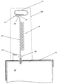
- the miniature antenna in accordance with the present invention comprises a base portion 10 and an essentially circular top loop 12, that is essentially perpendicular to the base portion 10.
- Top loop 12 comprises at least one, preferably a bit more than one turn.
- a U-shaped load 14 is provided between base portion 10 and top loop 12.
- the first leg 16 of load 14 is connected essentially perpendicular to base portion 10, while its second leg 18 is connected essentially tangential to top loop 12.
- the U-shaped load 14 increases the current flow to top loop 12. This gives the desired rectangular current distribution.
- the plane in which the U-shaped load 14 lies is perpendicular to top loop 12.
- Base portion 10 has a helically wound mid portion 20 comprising for instance about 10 turns. In the drawing the helix has uniform diameter.
- the whole antenna is formed by a single thread, which from base portion 10 extends into U-shaped load 14 and thereafter into top loop 12.
- the miniature antenna is suitably connected to a schematically shown transmitter/receiver 22, either directly or over a matching circuit comprising for instance a series capacitor 24 and a parallel inductor 30.
- a U-shaped metal band 26, forming an antenna aperture enlarging and chassis isolating metal grounding plane, can be provided between capacitor 24 and transmitter/receiver 22 at the current feeding point of the antenna.
- a band is especially suitable when the apparatus case comprises a metal frame.
- the purpose of the grounding plane is to decouple the antenna from the metal frame and to increase the antenna aperture. This is especially important for short antennas.
- a resonant band shaped metal grounding plane with a total electrical length of a half wave length follow the frame structure at a distance of one or a few millimeters and by letting this band have the same or a few millimeters larger width than the frame and by connecting the band to the frame only at the antenna connection point, it is possible to avoid current induction in the frame.
- the band In order to shorten the band it can be folded to form one or several pockets as in shown in the left part of the drawing. Such a pocket has the function of a shortening series inductor. Since the band does not lie directly on the frame, except at the current feeding point, similar pockets are formed also between the frame and the ends of the band.
- These pockets should have an electrical length that corresponds to a quarter of a wave length, referred to the mid frequency of the working range of the antenna, i. e. they should have a high input impedance to prevent current from being transferred to the frame.
- the band is shortened this becomes possible only by electrically extending the pocket by filling it with a dielectric that compensates for the shortening.
- the antenna is arranged non-symmetrically as in the drawing the antenna radiation is reduced in the direction towards the closest corner of the apparatus frame.
- the band can be extended more along the closest frame side to compensate for the radiation reduction.
- the antenna is embedded in a dielectric material, preferably with a dielectric constant of approximately 3, for instance silicone.
- the dielectric material can for instance be in the shape of a frustum of a cone 28, the thicker part of which surrounds elongated base portion 10 and the thinner part of which surrounds U-shaped load 14 and top loop 12.
- the antenna when combined with an ordinary sized pocket phone, preferably has the following data: Antenna length 31.5 mm Thread length (including inductor 30) 130 mm Thread diameter 0.75 mm Number of turns in base portion 11 Outer diameter 3.5 mm Length of wound portion 15.5 mm Number of turns in top loop 1.5 Outer diameter 8.5 mm Length of leg of U-shaped load 7 mm Height of load + top loop 3 mm Length between load and wound portion 3 mm Length between wound portion and pocket phone 10 mm Thread material silver plated copper Dielectric material in cone Sylgard 170 from DOW CORNING CORP, USA Cone diameter at top 12 mm Cone diameter at base 13 mm Capacitor 47 pf, ceramic Inductor 9 turns, outer diameter 2,5 mm, thread diameter 0,75 mm
- the dimensions of the antenna can be changed to make it suitable for other frequencies, for instance frequencies around 450 MHz or 1700 MHz.
Landscapes
- Details Of Aerials (AREA)
- Support Of Aerials (AREA)
- Pharmaceuticals Containing Other Organic And Inorganic Compounds (AREA)
- Nitrogen Condensed Heterocyclic Rings (AREA)
- Aerials With Secondary Devices (AREA)
Applications Claiming Priority (2)
| Application Number | Priority Date | Filing Date | Title |
|---|---|---|---|
| SE9102379A SE468917B (sv) | 1991-08-16 | 1991-08-16 | Miniatyrantenn |
| SE9102379 | 1991-08-16 |
Publications (2)
| Publication Number | Publication Date |
|---|---|
| EP0528775A1 EP0528775A1 (en) | 1993-02-24 |
| EP0528775B1 true EP0528775B1 (en) | 1996-09-11 |
Family
ID=20383488
Family Applications (1)
| Application Number | Title | Priority Date | Filing Date |
|---|---|---|---|
| EP92850177A Expired - Lifetime EP0528775B1 (en) | 1991-08-16 | 1992-07-22 | Miniature antenna |
Country Status (12)
| Country | Link |
|---|---|
| US (1) | US5592184A (enExample) |
| EP (1) | EP0528775B1 (enExample) |
| JP (1) | JP3382972B2 (enExample) |
| AT (1) | ATE142822T1 (enExample) |
| AU (1) | AU649866B2 (enExample) |
| CA (1) | CA2074015C (enExample) |
| DE (1) | DE69213621T2 (enExample) |
| FI (1) | FI112725B (enExample) |
| MX (1) | MX9204664A (enExample) |
| SE (1) | SE468917B (enExample) |
| SG (1) | SG52224A1 (enExample) |
| TW (1) | TW223188B (enExample) |
Families Citing this family (26)
| Publication number | Priority date | Publication date | Assignee | Title |
|---|---|---|---|---|
| SE512062C2 (sv) * | 1993-07-14 | 2000-01-17 | Ericsson Ge Mobile Communicat | Förfarande och anordning för att förbättra effektivitet och bandbredd för en antenn på en bärbar utrustning |
| EP0743699B1 (en) * | 1995-05-17 | 2001-09-12 | Murata Manufacturing Co., Ltd. | Surface mounting type antenna system |
| WO1997018601A1 (en) * | 1995-11-15 | 1997-05-22 | Allgon Ab | Dual band antenna means |
| DE19604034A1 (de) * | 1996-02-05 | 1997-08-07 | Aeg Mobile Communication | Endgespeiste Vertikalantenne für Handfunkgeräte |
| JP3146994B2 (ja) * | 1996-08-22 | 2001-03-19 | 株式会社村田製作所 | アンテナ及びその共振周波数調整方法 |
| JP3047836B2 (ja) * | 1996-11-07 | 2000-06-05 | 株式会社村田製作所 | ミアンダラインアンテナ |
| JP3580654B2 (ja) * | 1996-12-04 | 2004-10-27 | 京セラ株式会社 | 共用アンテナおよびこれを用いた携帯無線機 |
| US6724738B1 (en) | 1997-02-27 | 2004-04-20 | Motorola Inc. | Method and apparatus for acquiring a pilot signal in a CDMA receiver |
| US6144649A (en) * | 1997-02-27 | 2000-11-07 | Motorola, Inc. | Method and apparatus for acquiring a pilot signal in a CDMA receiver |
| GB2323476B (en) | 1997-03-20 | 2002-01-16 | David Ganeshmoorthy | Communication antenna and equipment |
| US5933121A (en) * | 1998-04-07 | 1999-08-03 | Harris Corporation | Antenna array for sensing signals on conductors |
| EP0987788A3 (en) * | 1998-09-18 | 2003-04-16 | The Whitaker Corporation | Multiple band antenna |
| US6781549B1 (en) | 1999-10-12 | 2004-08-24 | Galtronics Ltd. | Portable antenna |
| GB2380323B (en) * | 2001-09-29 | 2003-11-05 | Motorola Inc | Antenna for use in radio communications |
| US6914581B1 (en) * | 2001-10-31 | 2005-07-05 | Venture Partners | Focused wave antenna |
| EP1514329B1 (en) * | 2002-06-12 | 2014-01-01 | Thiss Technologies Pte Ltd | Helix antenna |
| WO2005001989A2 (en) * | 2003-06-25 | 2005-01-06 | The Board Of Governors For Higher Education | System and method for providing a distributed loaded monopole antenna |
| JP4770497B2 (ja) * | 2006-02-03 | 2011-09-14 | 日立電線株式会社 | アンテナ |
| KR101596188B1 (ko) | 2006-06-20 | 2016-02-19 | 인터디지탈 테크날러지 코포레이션 | 무선 통신 시스템에서의 핸드오버를 수행하기 위한 방법 및 시스템 |
| US7414587B2 (en) * | 2006-09-25 | 2008-08-19 | Shure Acquisition Holdings, Inc. | Antenna in a wireless system |
| TWI355778B (en) * | 2006-11-07 | 2012-01-01 | Wistron Neweb Corp | Portable electronic device with function of receiv |
| JP5676622B2 (ja) | 2009-10-16 | 2015-02-25 | イーエムエス・テクノロジーズ・カナダ,リミテッド | アレイアンテナの利得の増大のための最適負荷 |
| FR3008550B1 (fr) * | 2013-07-15 | 2015-08-21 | Inst Mines Telecom Telecom Bretagne | Antenne de type bouchon et structure antennaire et ensemble antennaire associes |
| US10931019B1 (en) * | 2015-12-14 | 2021-02-23 | Lockheed Martin Corporation | Helix antenna |
| US10283841B2 (en) | 2016-11-29 | 2019-05-07 | Shure Acquisition Holdings, Inc. | Wireless antenna |
| JP6422552B1 (ja) * | 2017-10-11 | 2018-11-14 | 株式会社ヨコオ | アンテナ装置 |
Family Cites Families (10)
| Publication number | Priority date | Publication date | Assignee | Title |
|---|---|---|---|---|
| US2993204A (en) * | 1958-02-28 | 1961-07-18 | Itt | Two-band helical antenna |
| CH499888A (fr) * | 1967-12-15 | 1970-11-30 | Onera (Off Nat Aerospatiale) | Antenne à un seul conducteur enroulé hélicoïdalement de dimensions réduites, et procédé pour sa fabrication |
| US4012744A (en) * | 1975-10-20 | 1977-03-15 | Itek Corporation | Helix-loaded spiral antenna |
| US4137534A (en) * | 1977-05-26 | 1979-01-30 | Goodnight Roy G | Vertical antenna with low angle of radiation |
| US4121218A (en) * | 1977-08-03 | 1978-10-17 | Motorola, Inc. | Adjustable antenna arrangement for a portable radio |
| US4161737A (en) * | 1977-10-03 | 1979-07-17 | Albright Eugene A | Helical antenna |
| AU3146384A (en) * | 1984-01-23 | 1985-08-01 | Emil Milan Barkovic | Variable antenna |
| US4697192A (en) * | 1985-04-16 | 1987-09-29 | Texas Instruments Incorporated | Two arm planar/conical/helix antenna |
| CA1257694A (en) * | 1985-08-05 | 1989-07-18 | Hisamatsu Nakano | Antenna system |
| US5216436A (en) * | 1991-05-31 | 1993-06-01 | Harris Corporation | Collapsible, low visibility, broadband tapered helix monopole antenna |
-
1991
- 1991-08-16 SE SE9102379A patent/SE468917B/sv not_active IP Right Cessation
-
1992
- 1992-07-16 TW TW081105615A patent/TW223188B/zh active
- 1992-07-16 CA CA002074015A patent/CA2074015C/en not_active Expired - Fee Related
- 1992-07-22 SG SG1996000709A patent/SG52224A1/en unknown
- 1992-07-22 DE DE69213621T patent/DE69213621T2/de not_active Expired - Fee Related
- 1992-07-22 EP EP92850177A patent/EP0528775B1/en not_active Expired - Lifetime
- 1992-07-22 AT AT92850177T patent/ATE142822T1/de not_active IP Right Cessation
- 1992-08-12 MX MX9204664A patent/MX9204664A/es not_active IP Right Cessation
- 1992-08-12 FI FI923614A patent/FI112725B/fi not_active IP Right Cessation
- 1992-08-13 JP JP21621792A patent/JP3382972B2/ja not_active Expired - Fee Related
- 1992-08-14 AU AU21011/92A patent/AU649866B2/en not_active Ceased
-
1995
- 1995-05-23 US US08/447,344 patent/US5592184A/en not_active Expired - Lifetime
Also Published As
| Publication number | Publication date |
|---|---|
| EP0528775A1 (en) | 1993-02-24 |
| SE468917B (sv) | 1993-04-05 |
| SE9102379L (sv) | 1993-02-17 |
| JP3382972B2 (ja) | 2003-03-04 |
| MX9204664A (es) | 1993-02-01 |
| AU2101192A (en) | 1993-02-18 |
| AU649866B2 (en) | 1994-06-02 |
| JPH05206715A (ja) | 1993-08-13 |
| CA2074015C (en) | 2001-02-20 |
| DE69213621T2 (de) | 1997-02-06 |
| ATE142822T1 (de) | 1996-09-15 |
| HK1006608A1 (en) | 1999-03-05 |
| CA2074015A1 (en) | 1993-02-17 |
| FI923614L (fi) | 1993-02-17 |
| SE9102379D0 (sv) | 1991-08-16 |
| FI923614A0 (fi) | 1992-08-12 |
| DE69213621D1 (de) | 1996-10-17 |
| SG52224A1 (en) | 1998-09-28 |
| TW223188B (enExample) | 1994-05-01 |
| FI112725B (fi) | 2003-12-31 |
| US5592184A (en) | 1997-01-07 |
Similar Documents
| Publication | Publication Date | Title |
|---|---|---|
| EP0528775B1 (en) | Miniature antenna | |
| CA2293396C (en) | Dual band antenna for mobile communications | |
| EP0855759B1 (en) | Simple dual-frequency antenna | |
| US6853338B2 (en) | Wireless GPS apparatus with integral antenna device | |
| EP1210745B1 (en) | Small sized multiple band antenna | |
| US5945963A (en) | Dielectrically loaded antenna and a handheld radio communication unit including such an antenna | |
| EP1202382B1 (en) | Antenna | |
| RU2183372C2 (ru) | Двухдиапазонная антенна | |
| RU2130673C1 (ru) | Двухфункциональная антенна для портативного устройства радиосвязи | |
| NZ264417A (en) | Printed film helical radio antenna with pitch varying from base to apex of helix | |
| KR20040067906A (ko) | 평면 안테나, 안테나 유닛 및 방송 수신 단말 장치 | |
| GB2189081A (en) | Monopole antenna | |
| US7053839B2 (en) | Antenna for a portable communication apparatus, and a portable communication apparatus comprising such an antenna | |
| EP0718909B1 (en) | Retractable top load antenna | |
| US6008765A (en) | Retractable top load antenna | |
| EP0876688B1 (en) | ANTENNA FOR FREQUENCIES IN EXCESS OF 200 MHz | |
| US6114999A (en) | Field controlled resonator | |
| US7053846B2 (en) | Spherical ring antenna | |
| EP1435125B1 (en) | Helical antenna | |
| HK1006608B (en) | Miniature antenna | |
| US4295144A (en) | Feed system for a circularly polarized tetra-coil antenna | |
| JPS6392103A (ja) | 小形アンテナ | |
| JP2004228796A (ja) | アンテナユニット、放送受信端末装置 | |
| JPH06318810A (ja) | 伸縮式アンテナ | |
| JPH07106842A (ja) | アンテナ装置 |
Legal Events
| Date | Code | Title | Description |
|---|---|---|---|
| PUAI | Public reference made under article 153(3) epc to a published international application that has entered the european phase |
Free format text: ORIGINAL CODE: 0009012 |
|
| AK | Designated contracting states |
Kind code of ref document: A1 Designated state(s): AT CH DE FR GB LI NL |
|
| 17P | Request for examination filed |
Effective date: 19930612 |
|
| 17Q | First examination report despatched |
Effective date: 19941229 |
|
| RAP3 | Party data changed (applicant data changed or rights of an application transferred) |
Owner name: ERICSSON INC. |
|
| GRAG | Despatch of communication of intention to grant |
Free format text: ORIGINAL CODE: EPIDOS AGRA |
|
| GRAH | Despatch of communication of intention to grant a patent |
Free format text: ORIGINAL CODE: EPIDOS IGRA |
|
| GRAH | Despatch of communication of intention to grant a patent |
Free format text: ORIGINAL CODE: EPIDOS IGRA |
|
| GRAA | (expected) grant |
Free format text: ORIGINAL CODE: 0009210 |
|
| AK | Designated contracting states |
Kind code of ref document: B1 Designated state(s): AT CH DE FR GB LI NL |
|
| REF | Corresponds to: |
Ref document number: 142822 Country of ref document: AT Date of ref document: 19960915 Kind code of ref document: T |
|
| REG | Reference to a national code |
Ref country code: CH Ref legal event code: NV Representative=s name: NOVATOR AG |
|
| REF | Corresponds to: |
Ref document number: 69213621 Country of ref document: DE Date of ref document: 19961017 |
|
| ET | Fr: translation filed |
Free format text: CORRECTIONS |
|
| PLBE | No opposition filed within time limit |
Free format text: ORIGINAL CODE: 0009261 |
|
| 26N | No opposition filed | ||
| REG | Reference to a national code |
Ref country code: GB Ref legal event code: IF02 |
|
| PGFP | Annual fee paid to national office [announced via postgrant information from national office to epo] |
Ref country code: AT Payment date: 20020703 Year of fee payment: 11 |
|
| PGFP | Annual fee paid to national office [announced via postgrant information from national office to epo] |
Ref country code: CH Payment date: 20020704 Year of fee payment: 11 |
|
| PG25 | Lapsed in a contracting state [announced via postgrant information from national office to epo] |
Ref country code: AT Free format text: LAPSE BECAUSE OF NON-PAYMENT OF DUE FEES Effective date: 20030722 |
|
| PG25 | Lapsed in a contracting state [announced via postgrant information from national office to epo] |
Ref country code: LI Free format text: LAPSE BECAUSE OF NON-PAYMENT OF DUE FEES Effective date: 20030731 Ref country code: CH Free format text: LAPSE BECAUSE OF NON-PAYMENT OF DUE FEES Effective date: 20030731 |
|
| REG | Reference to a national code |
Ref country code: CH Ref legal event code: PL |
|
| PGFP | Annual fee paid to national office [announced via postgrant information from national office to epo] |
Ref country code: NL Payment date: 20050629 Year of fee payment: 14 |
|
| PGFP | Annual fee paid to national office [announced via postgrant information from national office to epo] |
Ref country code: FR Payment date: 20050718 Year of fee payment: 14 |
|
| PG25 | Lapsed in a contracting state [announced via postgrant information from national office to epo] |
Ref country code: NL Free format text: LAPSE BECAUSE OF NON-PAYMENT OF DUE FEES Effective date: 20070201 |
|
| NLV4 | Nl: lapsed or anulled due to non-payment of the annual fee |
Effective date: 20070201 |
|
| REG | Reference to a national code |
Ref country code: FR Ref legal event code: ST Effective date: 20070330 |
|
| PG25 | Lapsed in a contracting state [announced via postgrant information from national office to epo] |
Ref country code: FR Free format text: LAPSE BECAUSE OF NON-PAYMENT OF DUE FEES Effective date: 20060731 |
|
| PGFP | Annual fee paid to national office [announced via postgrant information from national office to epo] |
Ref country code: DE Payment date: 20080829 Year of fee payment: 17 |
|
| PGFP | Annual fee paid to national office [announced via postgrant information from national office to epo] |
Ref country code: GB Payment date: 20080729 Year of fee payment: 17 |
|
| GBPC | Gb: european patent ceased through non-payment of renewal fee |
Effective date: 20090722 |
|
| PG25 | Lapsed in a contracting state [announced via postgrant information from national office to epo] |
Ref country code: GB Free format text: LAPSE BECAUSE OF NON-PAYMENT OF DUE FEES Effective date: 20090722 |
|
| PG25 | Lapsed in a contracting state [announced via postgrant information from national office to epo] |
Ref country code: DE Free format text: LAPSE BECAUSE OF NON-PAYMENT OF DUE FEES Effective date: 20100202 |