EP0528528B1 - Festhaltesystem für Kraftstoffilter - Google Patents
Festhaltesystem für Kraftstoffilter Download PDFInfo
- Publication number
- EP0528528B1 EP0528528B1 EP92306161A EP92306161A EP0528528B1 EP 0528528 B1 EP0528528 B1 EP 0528528B1 EP 92306161 A EP92306161 A EP 92306161A EP 92306161 A EP92306161 A EP 92306161A EP 0528528 B1 EP0528528 B1 EP 0528528B1
- Authority
- EP
- European Patent Office
- Prior art keywords
- base
- cartridge
- fuel filter
- ramp
- filter assembly
- Prior art date
- Legal status (The legal status is an assumption and is not a legal conclusion. Google has not performed a legal analysis and makes no representation as to the accuracy of the status listed.)
- Expired - Lifetime
Links
- 239000000446 fuel Substances 0.000 title claims description 50
- 230000014759 maintenance of location Effects 0.000 title description 11
- 230000002093 peripheral effect Effects 0.000 claims description 11
- 239000012530 fluid Substances 0.000 claims description 8
- 230000000717 retained effect Effects 0.000 claims description 7
- 238000004891 communication Methods 0.000 claims description 5
- XLYOFNOQVPJJNP-UHFFFAOYSA-N water Substances O XLYOFNOQVPJJNP-UHFFFAOYSA-N 0.000 description 6
- 239000002245 particle Substances 0.000 description 4
- 238000007789 sealing Methods 0.000 description 4
- 230000000295 complement effect Effects 0.000 description 3
- 239000002283 diesel fuel Substances 0.000 description 3
- 238000002347 injection Methods 0.000 description 3
- 239000007924 injection Substances 0.000 description 3
- 238000002485 combustion reaction Methods 0.000 description 2
- 239000013618 particulate matter Substances 0.000 description 2
- 230000002411 adverse Effects 0.000 description 1
- 238000004873 anchoring Methods 0.000 description 1
- 230000000712 assembly Effects 0.000 description 1
- 238000000429 assembly Methods 0.000 description 1
- 230000007797 corrosion Effects 0.000 description 1
- 238000005260 corrosion Methods 0.000 description 1
- 230000007812 deficiency Effects 0.000 description 1
- 230000003467 diminishing effect Effects 0.000 description 1
- 230000000694 effects Effects 0.000 description 1
- 238000001914 filtration Methods 0.000 description 1
- 230000008014 freezing Effects 0.000 description 1
- 238000007710 freezing Methods 0.000 description 1
- 238000010348 incorporation Methods 0.000 description 1
- 239000007788 liquid Substances 0.000 description 1
- 239000002184 metal Substances 0.000 description 1
- 238000000034 method Methods 0.000 description 1
- 238000003908 quality control method Methods 0.000 description 1
- 239000012858 resilient material Substances 0.000 description 1
Images


Classifications
-
- B—PERFORMING OPERATIONS; TRANSPORTING
- B01—PHYSICAL OR CHEMICAL PROCESSES OR APPARATUS IN GENERAL
- B01D—SEPARATION
- B01D35/00—Filtering devices having features not specifically covered by groups B01D24/00 - B01D33/00, or for applications not specifically covered by groups B01D24/00 - B01D33/00; Auxiliary devices for filtration; Filter housing constructions
- B01D35/30—Filter housing constructions
-
- B—PERFORMING OPERATIONS; TRANSPORTING
- B01—PHYSICAL OR CHEMICAL PROCESSES OR APPARATUS IN GENERAL
- B01D—SEPARATION
- B01D27/00—Cartridge filters of the throw-away type
- B01D27/08—Construction of the casing
Definitions
- This invention relates generally to devices for filtering and separating liquids. More particularly, the present invention relates to fuel filters for removing foreign particles and separating water from fuel and fuel supply systems of an internal combustion engine.
- Fuel filters commonly employ a disposable filter cartridge which is replaced at pre-established intervals of filter usage.
- the replaceable cartridge is conventionally secured to the base and/or locked to the base by a locking mechanism which is releasable to allow for removal of the cartridge for replacement purposes.
- one disclosed inverted fuel filter assembly employs a base which mounts to the vehicle and a disposable filter cartridge which is suspended directly below the filter base.
- the cartridge is retained to the base by a threaded collar.
- the collar includes a rim which retentively engages against a roll seam structure at the periphery of the cartridge housing. The collar threads to the base. The cartridge is replaced by loosening the threaded collar and dismounting the filter cartridge.
- the conventional threaded locking can introduce uneven loading between different fuel filter assemblies as well as within a given fuel filter depending upon the degree of tightening or torque applied to the retainer collar.
- the threads are subject to exposure to various fluids and particulate matter which may seriously jeopardize the integrity and efficiency of the threaded engagement.
- Improper loading can affect the sealing integrity of the fuel filter system and the structural integrity of the cartridge, thereby jeopardizing the effectiveness of the fuel filter and/or diminishing the useful life of the fuel filter.
- British patent No. 656,209 discloses a quickly removable filter casing cover.
- the casing cover has a flange provided with inwardly extending projections that are sized and positioned to pass through spaces between four complementary projections on the casing body.
- the flange projections may have inclined upper surfaces so that the cover will be drawn downwardly on the casing when the coyer is rotated in a clockwise direction.
- the cover projections extend upwardly at one end to provide a stop.
- European Patent No. 221,675 discloses a fluid filter having complementary interengageable locking devices formed radially on the filter and filter mount for engaging the filter and the filter mount.
- the locking devices include a first set of circumferentially spaced flanges formed on the inner wall of the housing and a second set of circumferentially spaced flanges formed on the filter mount. The first set of flanges is inserted between the second set of flanges and the filter is turned a quarter turn to engage the filter and the filter mount.
- fuel filter assembly comprising a base having a receptacle, a disposable cartridge connectable to the base, at least a portion of the cartridge being receivable in the receptacle, the cartridge having a peripheral engagement shoulder, and a retainer collar having a retainer portion engageable against the shoulder characterized by:
- a fuel filter assembly comprising a base defining a receiving structure, a disposable cartridge connectable to the base for housing a filter element, at least a portion of the cartridge being receivable in the structure, the cartridge having a peripheral first shoulder, and a retainer collar having a second shoulder engageable against the first shoulder characterized by:
- the invention in a preferred form is a retention system for a fuel filter assembly of a type comprising a base, a disposable cartridge and a retainer collar which locks the cartridge to the base.
- the base has an inverted cup-like receiving skirt.
- a spiral ramp extends at the exterior of the skirt.
- a stop is angularly spaced from an upper end of the ramp so as to define a detentive slot.
- the disposable cartridge houses one or more filter elements and is partially receivable by the base skirt.
- the cartridge has a peripheral engagement flange.
- the retainer collar has a shoulder which is engageable against the flange and an integral inner spiral follower which terminates in a catch.
- the follower is slidably engageable against the base ramp. As the collar is angularly rotated, the follower rides the base ramp until the catch engages the stop and is positively captured in the slot and the follower seats against the ramp to thereby releasably lock the cartridge to the base.
- the base has two substantially identical spiral ramps.
- the base and the collar has two substantially identical spiral followers and the collar followers may engage in surface-to-surface contact which extends in excess of 180° in the locked position.
- a spring may function to bias the catch to the locked position.
- the spring is a spring washer which has an inscribed star-like configuration.
- the spring washer has two alternating sets of spring leaves. One of the sets is engageable against the disposable cartridge and the second set is engageable against the base.
- the washer also has a peripheral portion which is engageable against radially outer portions of the received end of the cartridge.
- the spring washer has eight spring leaves.
- the spring washer may be retained to the base by means of a retainer ring.
- the ring is crimped to an axial conduit which provides fluid communication between the cartridge and the base.
- Fuel filter assembly 10 comprises a base 12 and a disposable cartridge 14.
- the fuel filter assembly is especially adapted for incorporation into the fuel supply system of an internal combustion engine (not illustrated), such as a diesel engine, for removing particulate matter from the fuel and for separating water from the fuel.
- the base is disposed generally above the disposable filter cartridge which is locked to the base by means of a retainer collar 16.
- the base 12 and the disposable cartridge 14 may assume a wide variety of configurations.
- the base 12 is an inverted cup-like-receptacle which forms a skirt defining a lower receiving cavity for upper portions of the disposable cartridge.
- a central stepped axial bore 22 in the base closely receives an elongated sleeve-like conduit 24 and an outer concentric sleeve-like conduit 26.
- the conduits provide generally coaxial fluid communication between the base and the disposable cartridge.
- An inlet connector 30 at an upper side location of the base connects with the fuel line to provide fluid communication through the passageway defined by the first conduit 24.
- An outlet connector 32 at an upper side location of the base connects with a fuel line to provide external fluid communication from the axial fluid conduit defined between the first and second conduits 24 and 26.
- An integral projecting bracket 40 which may include a pair of openings 42,44 for anchoring the filter base to the engine header, projects transversely from the base. Alternately, the base does not have a bracket structure but merely has a pair of fastener openings. The base may also have an air vent 46.
- the disposable filter cartridge 14 comprises a can-like container comprising a pair of lower and upper cup-like sections 52,54, which are joined along a circumferential roll seam 60.
- the upper section 52 is smaller in diameter than the lower section.
- the upper section 52 is received in the base receptacle and includes a central axial opening.
- the upper section 52 is dimensioned so that is is closely accommodated in the base receptacle. In one embodiment, the distance between the adjacent receptacle and cartridge side surfaces is of the order of 0.0075 inches (0.2mm).
- a sealing grommet 56 mounted at the opening diametrally seals against the outer conduit 26.
- An integral annular lip 57 projects from the top surface of the section 52.
- a secondary filter element (not illustrated) which has a continuous fan-shape pleated configuration is mounted in the upper section.
- a lower end of the secondary element is engaged by a medial plate which has a central recess.
- a second sealing grommet mounted at the recess diametrally seals against the first conduit 24.
- the primary filter element which also has a continuous fan-like configuration, engages the underside of the medial plate and is retained by a lower plate.
- the primary element is housed in the lower section 54.
- a sump is formed at the bottom of the lower section to collect water which coalesces from the fuel.
- the retainer collar 16 includes an inwardly projecting annular shoulder 80 which engages the roll seam 60 of the cartridge for retentively locking the disposable cartridge to the base.
- the collar includes a pair of diametrically disposed spiral follower or ramps 82 and 84 which integrally extend inwardly from the collar.
- the followers respectively upwardly terminate in catches 86 and 88 which protrude downwardly at the upper terminus underside of the followers 82 and 84.
- the lower trailing portions of the catches have tapered contoured surfaces 87 and 89.
- the base includes a pair of integral outwardly projecting, diametrically disposed ramps 90 and 92.
- Each of the ramps ascends in spiral-like fashion in excess of 90° around the base.
- the upper ends of the ramps are beveled.
- Stops 94 and 96 are angularly spaced from the respective upper ends of the ramps so that a retentive slot is defined between the upper beveled end of each ramp and the end of the corresponding stop.
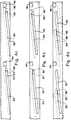
- the followers 82, 84 including the catches 86, 88 of the collar are dimensioned and positionable for engagement with the ramps 90, 92 and stops 94, 96 of the base, so that the followers 82, 84 slidably engage and ascend the ramps 90,92 upon alignment and angular rotation of the collar as illustrated in Figure 4a.
- the maximum elevated relationship between the followers and ramps is illustrated in Figure 4b.
- both of the catches 86,88 positively seat in the slots.
- the inclination angle of the upper surfaces of the ramp and the underside surfaces of the followers are constant and substantially equal.
- the upper ramp surfaces of the base ramps and the underside surface of the retainer collar followers engage along an extended substantially surface-to-surface interface, as best illustrated in Figure 4c.
- the locked position of Figure 4c may be facilitated by the leading end of the catches 86 and 88 engaging the stops 94 and 96, respectively.
- the positive locked position is releasably maintained by the force of a spring 100 which is mounted to the base.
- a preferred embodiment is a spring washer having an inscribed star-like configuration and a central opening dimensioned to accommodate conduit 26.
- the spring 100 may be retained by a retainer ring 102 which is crimped to the conduit 26. Alternately, the spring may be retained by an integral shoulder formed on the conduit 24.
- the spring washer includes angularly alternating spring leaves 110 and 112 which are alternately biased as best illustrated in Figures 6, 7 and 8. The spring leaves are biased so that the first set engages against an abutment portion of the base, and the second set engages against the top of the disposable cartridge.
- the multiple spring engagement interfaces function to substantially uniformly distribute the load between the base and the cartridge.
- a peripheral shoulder portion 114 of the spring is engageable against the upwardly protruding lip 57 of the disposable cartridge.
- the spring bias provides the positive releasable locking engagement to urge the catches into the slots to thereby releasably lock the disposable cartridge to the base.
- the initial rotation of the collar causes the collar follower and the leading catches to ride up the base ramps as illustrated in Figure 4a.
- the catches eventually reach an elevated position above the base ramp as best illustrated in Figure 4b.
- the torque applied to the collar is resisted by the bias force of the spring 100.
- Continued angular rotation of the collar causes the catches to clear the upper ramp ends and/or engage the stops under the spring bias to snap into the retentive slots as illustrated in Figure 4c.
- the dwell or locked position is releasably retained by the bias of the spring 100.
- the drop from the elevated Figure 4b position to the locked Figure 4c position is on the order of 0.030 inches (0.8mm).
- the angularly spaced leaves 110,112 and the peripheral spring shoulder 114 cooperate to generally uniformly distribute the spring bias force by providing multiple spaced engagement locations.
- the spring 100 is not required.
- the bias which maintains the locked position is provided by a deformable portion of the retainer collar which is made from metal or other resilient material. The deformable portion imposes a bias when the collar is rotated to the locked position.
- the complementary spiral follower and ramp structures provide a relatively large angular engagement surface in the locked position.
- the engagement interfaces of the followers and ramps subtend an angle on the order of 300°.
- the extended engagement surfaces provide for a very stable loaded relationship between the disposable cartridge and the base.
- the spring washer 100 is also configured so that it contacts a central portion of the disposable cartridge and also provides a secondary contact at an outer peripheral portion to provide stability to the loaded cartridge and thereby eliminate rocking of the cartridge.
- the bias force which is applied by the leaves 110 at the center portion to the cartridge enhances the resistance of the structure of the cartridge housing so as to effectively resist structural failure resulting from the high pressures that may be applied to the cartridge.
- the present invention provides a new and improved retention system for releasably retaining a disposable cartridge to the base of a fuel filter;
Landscapes
- Chemical & Material Sciences (AREA)
- Chemical Kinetics & Catalysis (AREA)
- Quick-Acting Or Multi-Walled Pipe Joints (AREA)
- Filtration Of Liquid (AREA)
Claims (15)
- Kraftstoffilteranordnung, umfassend: eine Basis (12) mit einer Aufnahme, eine an die Basis anschließbare Einwegpatrone (14), wobei zumindest ein Abschnitt der Patrone in der Aufnahme aufnehmbar ist, wobei die Patrone eine Umfangseingriffsschulter (60) aufweist, sowie einen Haltekragen (16) mit einem Halteabschnitt (80) zur Anlage an der Schulter,
dadurch gekennzeichnet,daß die Basis ein Rampenmittel (90, 92) aufweist, das an der Außenseite der Aufnahme eine erste Spiralrampe festlegt, sowie einen Anschlag (94), der mit Winkelabstand von der ersten Rampe angeordnet ist und zwischen diesen einen Schlitz bildet; unddaß der Haltekragen ein Folgermittel (82, 84) mit einer Falle (86, 88) an seinem einen Ende aufweist, wobei das Folgermittel mit dem Rampenmittel derart in Eingriff bringbar ist, daß bei Winkeldrehung des Kragenmittels das Folgermittel das Rampenmittel entlangläuft und das Fallenmittel sich zum Auffangen in den Schlitz bewegt, um hierdurch die Patrone an der Basis zu verriegeln. - Kraftstoffilteranordnung nach Anspruch 1, in der das Rampenmittel (90, 92) ein Paar diametral gegenüberliegendar Rampen aufweist und das Folgermittel (82, 84) ein Paar diametral gegenüberliegender Folger aufweist.
- Kraftstoffilteranordnung nach Anspruch 1 oder 2, in der der Kragen (16) die Patrone (14) an der Basis (12) derart verriegelt, daß das Rampenmittel (90, 92) und das Folgermittel (82, 84) in gegenseitigem Oberflächenkontakt in Eingriff treten, der sich über einen Winkel von mehr als 180° erstreckt.
- Kraftstoffilteranordnung nach einem der Ansprüche 1 bis 3, die ferner ein Federmittel (100) zum Eingriff mit dem Patronenmittel (14) umfaßt, um in der verriegelten Stellung die Falle (86, 88) zur Positionierung in den Schlitz hinein vorzuspannen.
- Kraftstoffilteranordnung nach Anspruch 4, in der das Federmittel (100) eine Federscheibe umfaßt.
- Kraftstoffilter nach Anspruch 5, in dem die Federscheibe (100) eine innensternartige Konfiguration mit zwei Sätzen von Federblättern (110, 112) aufweist, wobei ein Satz der Federblätter (110) mit der Einwegpatrone (14) in Eingriff bringbar ist und der zweite Satz der Federblätter (112) mit der Basis (12) in Eingriff bringbar ist.
- Kraftstoffilteranordnung nach Anspruch 5 oder 6, in der die Federscheibe (100) ferner einen Umfangsabschnitt (114) aufweist, der zusätzlich mit radial äußeren Abschnitten der Patrone (14) in Eingriff bringbar ist.
- Kraftstoffilteranordnung nach einem der Ansprüche 5 bis 7, in der die Federscheibe (100) acht Federblätter aufweist.
- Kraftstoffilteranordnung nach einem der Ansprüche 5 bis 8, in der die Federscheibe (100) an dem Basismittel (12) mittels eines Halterings (102) gehalten ist und in der die Basis ferner eine Leitung (12) aufweist, die eine Fluidverbindung zwischen der Patrone (14) und der Basis ergibt, wobei der Haltering an der Außenseite der Leitung gesichert ist.
- Kraftstoffilteranordnung, umfassend: eine eine Aufnahmestruktur festlegende Basis (12), eine an die Basis anschließbare Einwegfilterpatrone (14) zur Aufnahme eines Filterelements, wobei zumindest ein Abschnitt der Patrone in der Struktur aufnehmbar ist, wobei die Patrone eine erste Umfangsschulter (60) aufweist, sowie einen Haltekragen (16) mit einer zweiten Schulter (80) zur Anlage an der ersten Schulter,
gekennzeichnet durch:ein Vorspannmittel (100) zum axialen Vorspannen der Patrone von der Basis, wenn die Patrone an die Basis angeschlossen ist;wobei die Basis ein Rampenmittel (90, 92) an der Außenseite der Struktur aufweist zur Bildung einer Spiralrampe, die in einem ersten Ende endet; undwobei der Haltekragen einen inneren Folger (82, 84) aufweist, der in einer Falle (86, 88) endet, wobei die Falle mit der ersten Rampe in Gleiteingriff bringbar ist, wenn der Kragen im Winkel gedreht wird, so daß der innere Folger die erste Rampe entlangläuft und die Falle an dem Rampenende vorbeigleitet, um hierdurch das Patronenmittel an dem Basismittel lösbar zu verriegeln. - Kraftstoffilteranordnung nach Anspruch 10, in der die Basis (12) zwei im wesentlichen identische diametral gegenüberliegende Rampen aufweist und der Kragen ferner einen zweiten Folger (84) aufweist, der in einer zweiten Falle (88) endet, wobei die Folger (82, 84) allgemein diametral gegenüberliegen.
- Kraftstoffilteranordnung nach Anspruch 10 oder 11, in dem der Kragen (16) die Patrone (14) an der Basis (12) derart verriegelt, daß das Rampenmittel (90, 92) und der Folger (82, 84) im gegenseitigen Oberflächenkontakt in Eingriff treten, der sich über mehr als 180° erstreckt.
- Kraftstoffilteranordnung nach einem der Ansprüche 10 bis 12, in der das Vorspannmittel (100) eine Federscheibe mit einer innensternartigen Konfiguration und zwei Sätzen von Federblättern (110, 112) aufweist, wobei ein Satz der Federblätter (110) mit der Einwegpatrone (14) in Eingriff bringbar ist und der zweite Satz der Federblätter (112) mit der Basis (12) in Eingriff bringbar ist, und wobei die Scheibe ferner einen Umfangsabschnitt (114) aufweist, der zusätzlich mit radial äußeren Abschnitten der Patrone in Eingriff bringbar ist.
- Kraftstoffilteranordnung nach einem der Ansprüche 10 bis 13, in der die Basis (12) ferner mit Abstand von dem ersten Ende einen Anschlag (94, 96) aufweist, wobei die Falle (86, 88) mit dem Anschlag in Eingriff bringbar ist.
- Kraftstoffilteranordnung nach einem der Ansprüche 10 bis 14, in der das erste Ende eine Kegelfläche aufweist und die Falle (86, 88) eine verjüngte Fläche (87, 89) aufweist, die in der verriegelten Stellung an die Kegelfläche angreift.
Applications Claiming Priority (2)
| Application Number | Priority Date | Filing Date | Title |
|---|---|---|---|
| US746693 | 1991-08-16 | ||
| US07/746,693 US5203994A (en) | 1991-08-16 | 1991-08-16 | Fuel filter retention system |
Publications (2)
| Publication Number | Publication Date |
|---|---|
| EP0528528A1 EP0528528A1 (de) | 1993-02-24 |
| EP0528528B1 true EP0528528B1 (de) | 1997-01-02 |
Family
ID=25001930
Family Applications (1)
| Application Number | Title | Priority Date | Filing Date |
|---|---|---|---|
| EP92306161A Expired - Lifetime EP0528528B1 (de) | 1991-08-16 | 1992-07-03 | Festhaltesystem für Kraftstoffilter |
Country Status (5)
| Country | Link |
|---|---|
| US (1) | US5203994A (de) |
| EP (1) | EP0528528B1 (de) |
| JP (1) | JP3337146B2 (de) |
| DE (1) | DE69216322T2 (de) |
| ES (1) | ES2096036T3 (de) |
Families Citing this family (54)
| Publication number | Priority date | Publication date | Assignee | Title |
|---|---|---|---|---|
| WO1993014858A1 (en) * | 1992-01-22 | 1993-08-05 | Allied-Signal Inc. | Quick connect/disconnect liquid filter |
| US5302284A (en) * | 1992-12-23 | 1994-04-12 | Stanadyne Automotive Corp. | Fuel filter with spring-loaded retention system |
| FR2708478B1 (fr) * | 1993-08-02 | 1996-02-02 | Labinal | Perfectionnements apportés aux boîtiers pour filtres à liquide. |
| EP0638348B1 (de) * | 1993-08-02 | 1996-08-28 | Filtrauto | Verbesserungen bei oder in Bezug auf Flüssigkeitsfiltergehäuse |
| US5484527A (en) * | 1993-12-13 | 1996-01-16 | Stanadyne Automotive Corp. | Module for filter assembly base |
| FR2745196B1 (fr) * | 1996-02-23 | 1998-05-15 | Filtrauto | Filtre a cartouche amovible pour moteur a combustion interne |
| US5915926A (en) * | 1996-04-19 | 1999-06-29 | Stanadyne Automotive Corp. | Lift pump for filter module |
| US5837137A (en) * | 1996-08-21 | 1998-11-17 | Stanadyne Automotive Corp. | Base/cartridge location and key system for fuel filter assembly |
| DE19706644A1 (de) * | 1997-02-20 | 1998-08-27 | Knecht Filterwerke Gmbh | Kunststoff-Deckel für ein Filtergehäuse |
| GB9707218D0 (en) * | 1997-04-08 | 1997-05-28 | Lucas Ind Plc | Filter arrangement |
| FR2774548B1 (fr) * | 1998-02-02 | 2000-03-03 | Soudure Autogene Francaise | Ensemble tuyere/porte-tuyere pour torche a plasma |
| US6187188B1 (en) * | 1999-07-19 | 2001-02-13 | Stanadyne Automotive Corp. | Filter cartridge retention system |
| US6217763B1 (en) | 1999-08-11 | 2001-04-17 | Usf Filtration And Separation Group, Inc. | Back-flushable filter cartridge assemblies |
| FR2799661B1 (fr) * | 1999-10-18 | 2002-04-12 | Filtrauto | Boitier de filtre a couvercle vissable encliquetable |
| EP1128060A3 (de) | 2000-02-16 | 2002-05-02 | Stanadyne Automotive Corp. | Filterkopf mit selbstsperrender Filterhalterung |
| DE60124331T2 (de) * | 2000-02-16 | 2007-02-15 | Stanadyne Corp., Windsor | Befestigungssystem für ökologische Filterpatrone und Filterelement |
| US20030019819A1 (en) * | 2001-07-30 | 2003-01-30 | Karl Fritze | Hot disconnect replaceable water filter assembly |
| WO2003080215A1 (en) * | 2002-03-18 | 2003-10-02 | Donaldson Company, Inc. | Fluid filter having interchangeable top-load filter and bottom-load filter and methods |
| DE10232043A1 (de) * | 2002-07-16 | 2004-02-05 | Mann + Hummel Gmbh | Filtereinrichtung |
| DE10232046A1 (de) * | 2002-07-16 | 2004-01-29 | Mann + Hummel Gmbh | Filtereinrichtung |
| KR100534868B1 (ko) * | 2002-10-01 | 2005-12-08 | 현대자동차주식회사 | 차량용 연료필터 |
| US6881334B2 (en) * | 2002-10-31 | 2005-04-19 | Stanadyne Corporation | Eccentric interference retention system for a filter cartridge |
| US6863811B2 (en) * | 2002-10-31 | 2005-03-08 | Stanadyne Corporation | Filter cartridge incorporating a peripheral compatibility matrix |
| US20050161394A1 (en) * | 2002-11-20 | 2005-07-28 | Karl Fritze | Freeze resistant water filter |
| US20040232064A1 (en) * | 2003-05-23 | 2004-11-25 | James Wilkinson | Cartridge filters and housing connections therefor |
| JP4036153B2 (ja) * | 2003-07-22 | 2008-01-23 | 株式会社日立製作所 | ダンパ機構及び高圧燃料供給ポンプ |
| EP1735073B1 (de) * | 2004-04-05 | 2009-08-19 | 3M Innovative Properties Company | Austauschbare heisstrennwasserfilteranordnung |
| AU2006216788B2 (en) * | 2005-02-22 | 2011-08-04 | Baldwin Filters, Inc. | Filter apparatus |
| US8057669B2 (en) * | 2005-02-22 | 2011-11-15 | Baldwin Filters, Inc. | Filter element and filter assembly including locking mechanism |
| JP4502905B2 (ja) * | 2005-08-09 | 2010-07-14 | 本田技研工業株式会社 | リッド分離型容器 |
| WO2007041559A2 (en) * | 2005-09-30 | 2007-04-12 | Stanadyne Corporation | Water separation and filtration structure |
| US20080000820A1 (en) * | 2006-06-30 | 2008-01-03 | Mitchell Alan J | Water Filter Cartridge and Valve with Autobypass Feature |
| US8147691B2 (en) * | 2007-09-21 | 2012-04-03 | Baldwin Filters, Inc. | Filter cartridge housing attachment systems |
| US8501003B2 (en) * | 2007-10-17 | 2013-08-06 | Caterpillar Inc. | Canister filter system with drain that cooperates with filter element |
| US8157997B2 (en) | 2007-10-17 | 2012-04-17 | Caterpillar Inc. | Canister filter system with drain that cooperates with filter element |
| US8419938B2 (en) * | 2007-11-19 | 2013-04-16 | Catepillar Inc. | Fluid filter system |
| US8272516B2 (en) | 2007-11-19 | 2012-09-25 | Caterpillar Inc. | Fluid filter system |
| US8496821B2 (en) * | 2007-12-28 | 2013-07-30 | Caterpillar Inc. | Systems and methods for filtering fuel |
| US8815090B2 (en) * | 2008-06-16 | 2014-08-26 | Baldwin Filters, Inc. | Filter with water separation device |
| US8128819B2 (en) * | 2008-06-16 | 2012-03-06 | Baldwin Filters Inc. | Fluid filter, fluid filter assembly, and mounting method |
| US8241493B2 (en) | 2008-06-16 | 2012-08-14 | Baldwin Filters, Inc. | Filter with ejection mechanism |
| US20100155321A1 (en) * | 2008-12-23 | 2010-06-24 | Sasur Timothy M | Filter assembly |
| US8061530B2 (en) | 2009-04-09 | 2011-11-22 | Cummins Filtration Ip, Inc. | Filtration sealing system |
| DE102010027785B4 (de) * | 2010-04-15 | 2020-12-03 | Hengst Se | Ölnebelabscheider mit einem Gehäuse mit abnehmbarem Deckel |
| DE102010043836A1 (de) * | 2010-11-04 | 2012-05-10 | Hengst Gmbh & Co. Kg | Filter mit einem austauschbaren Filtereinsatz |
| US8991619B2 (en) | 2012-03-26 | 2015-03-31 | Baldwin Filters, Inc. | Filter assembly with water evacuation and methods |
| MX360860B (es) | 2013-01-04 | 2018-11-20 | Baldwin Filters Inc | Tapa extrema tripartita y elemento de filtro que la incluye. |
| DE112017000710T5 (de) | 2016-03-18 | 2018-10-31 | Cummins Filtration Ip, Inc. | Gekuppelte stabile Filterbaugruppe |
| WO2017192441A1 (en) | 2016-05-02 | 2017-11-09 | Cummins Filtration Ip, Inc. | Filter with interlocking housing interface |
| BR112019006701B1 (pt) | 2016-10-03 | 2022-11-01 | Parker-Hannifin Corporation | Cartucho de filtro, montagem de elemento de filtro e montagem de cabeçote |
| DE112018000527T5 (de) | 2017-01-25 | 2019-10-10 | Cummins Filtration Ip, Inc. | Erweiterbarer gewindeadapter für gewindelosen mantel |
| DE112018000382T5 (de) | 2017-02-21 | 2019-09-26 | Cummins Filtration Ip, Inc. | Gewellte ineinandergreifende Gehäuse-Endplatten-Schnittstellengeometrie |
| CN110446539B (zh) | 2017-03-16 | 2022-07-08 | 康明斯滤清系统知识产权公司 | 过滤密封系统 |
| WO2018222804A2 (en) | 2017-05-31 | 2018-12-06 | Parker-Hannifin Corporation | Filter element with torsion lock and/or sliding piston, assembly and methods |
Family Cites Families (8)
| Publication number | Priority date | Publication date | Assignee | Title |
|---|---|---|---|---|
| GB656209A (en) * | 1948-10-04 | 1951-08-15 | Fram Corp | Quickly removable filter casing cover |
| US3502221A (en) * | 1968-05-14 | 1970-03-24 | Spraying Systems Co | Filter unit for sprayers |
| GB1296051A (de) * | 1969-03-06 | 1972-11-15 | ||
| US4764275A (en) * | 1985-10-25 | 1988-08-16 | Robichaud Arthur W | Fluid filter and method for attaching same in sealing relation to a filter mount |
| CA1306956C (en) * | 1986-01-27 | 1992-09-01 | Raymond M. Petrucci | Quick-change filter cartridge and head therefor |
| NL8702806A (nl) * | 1987-11-23 | 1989-06-16 | Fairey Arlon Bv | Filterinrichting en filterpatroon daarvoor. |
| US4992166A (en) * | 1988-06-13 | 1991-02-12 | Facet Enterprises, Inc. | Plastic fluid filter and method for manufacturing same |
| US5017285A (en) * | 1989-06-28 | 1991-05-21 | Stanadyne Automotive Corp. | Fuel filter and cartridge assembly |
-
1991
- 1991-08-16 US US07/746,693 patent/US5203994A/en not_active Expired - Lifetime
-
1992
- 1992-07-03 EP EP92306161A patent/EP0528528B1/de not_active Expired - Lifetime
- 1992-07-03 DE DE69216322T patent/DE69216322T2/de not_active Expired - Lifetime
- 1992-07-03 ES ES92306161T patent/ES2096036T3/es not_active Expired - Lifetime
- 1992-08-14 JP JP23902092A patent/JP3337146B2/ja not_active Expired - Lifetime
Also Published As
| Publication number | Publication date |
|---|---|
| US5203994A (en) | 1993-04-20 |
| JP3337146B2 (ja) | 2002-10-21 |
| ES2096036T3 (es) | 1997-03-01 |
| DE69216322T2 (de) | 1997-04-24 |
| DE69216322D1 (de) | 1997-02-13 |
| EP0528528A1 (de) | 1993-02-24 |
| JPH05261210A (ja) | 1993-10-12 |
Similar Documents
| Publication | Publication Date | Title |
|---|---|---|
| EP0528528B1 (de) | Festhaltesystem für Kraftstoffilter | |
| EP0607563B1 (de) | Brennstofffilter mit federbelastetem Haltesystem | |
| EP0529286B1 (de) | Filteraufbau mit anbaubarem Wasserablassbehälter und anbaubarer Wasserablassbehälter | |
| EP0826406B1 (de) | Sockel/Kartuschen-Befestigung und Arretierungssystem für Kraftstoffilter | |
| US6187188B1 (en) | Filter cartridge retention system | |
| US6364121B1 (en) | Filter cartridge with grommet spring | |
| US5186829A (en) | Fuel filter key system | |
| EP0405447B1 (de) | Kraftstoff-Filter | |
| US6500335B2 (en) | Filter system base module with self-locking cartridge retainer | |
| EP1126159B1 (de) | Befestigungssytem für ökologische Filterpatrone und Filterelement | |
| US6481580B1 (en) | Fluid filter with locking mechanism | |
| WO1991003301A1 (en) | Fuel filter | |
| US6881334B2 (en) | Eccentric interference retention system for a filter cartridge | |
| US6814243B2 (en) | Replaceable filter with locking mechanism | |
| US20020043506A1 (en) | Slip resistant filter housing | |
| US11938429B2 (en) | Filter device and method of manufacturing the filter device |
Legal Events
| Date | Code | Title | Description |
|---|---|---|---|
| PUAI | Public reference made under article 153(3) epc to a published international application that has entered the european phase |
Free format text: ORIGINAL CODE: 0009012 |
|
| AK | Designated contracting states |
Kind code of ref document: A1 Designated state(s): DE ES FR GB IT |
|
| 17P | Request for examination filed |
Effective date: 19930723 |
|
| 17Q | First examination report despatched |
Effective date: 19941109 |
|
| GRAG | Despatch of communication of intention to grant |
Free format text: ORIGINAL CODE: EPIDOS AGRA |
|
| GRAH | Despatch of communication of intention to grant a patent |
Free format text: ORIGINAL CODE: EPIDOS IGRA |
|
| GRAH | Despatch of communication of intention to grant a patent |
Free format text: ORIGINAL CODE: EPIDOS IGRA |
|
| GRAA | (expected) grant |
Free format text: ORIGINAL CODE: 0009210 |
|
| AK | Designated contracting states |
Kind code of ref document: B1 Designated state(s): DE ES FR GB IT |
|
| ET | Fr: translation filed | ||
| REF | Corresponds to: |
Ref document number: 69216322 Country of ref document: DE Date of ref document: 19970213 |
|
| REG | Reference to a national code |
Ref country code: ES Ref legal event code: FG2A Ref document number: 2096036 Country of ref document: ES Kind code of ref document: T3 |
|
| ITF | It: translation for a ep patent filed |
Owner name: 0414;03RMFSOCIETA' ITALIANA BREVETTI S.P |
|
| PLBI | Opposition filed |
Free format text: ORIGINAL CODE: 0009260 |
|
| 26 | Opposition filed |
Opponent name: ROBERT BOSCH GMBH Effective date: 19970926 |
|
| PLBF | Reply of patent proprietor to notice(s) of opposition |
Free format text: ORIGINAL CODE: EPIDOS OBSO |
|
| PLBF | Reply of patent proprietor to notice(s) of opposition |
Free format text: ORIGINAL CODE: EPIDOS OBSO |
|
| PLBF | Reply of patent proprietor to notice(s) of opposition |
Free format text: ORIGINAL CODE: EPIDOS OBSO |
|
| PLBO | Opposition rejected |
Free format text: ORIGINAL CODE: EPIDOS REJO |
|
| APAC | Appeal dossier modified |
Free format text: ORIGINAL CODE: EPIDOS NOAPO |
|
| APAE | Appeal reference modified |
Free format text: ORIGINAL CODE: EPIDOS REFNO |
|
| APAC | Appeal dossier modified |
Free format text: ORIGINAL CODE: EPIDOS NOAPO |
|
| REG | Reference to a national code |
Ref country code: GB Ref legal event code: IF02 |
|
| APAC | Appeal dossier modified |
Free format text: ORIGINAL CODE: EPIDOS NOAPO |
|
| PLBN | Opposition rejected |
Free format text: ORIGINAL CODE: 0009273 |
|
| STAA | Information on the status of an ep patent application or granted ep patent |
Free format text: STATUS: OPPOSITION REJECTED |
|
| 27O | Opposition rejected |
Effective date: 20030310 |
|
| REG | Reference to a national code |
Ref country code: FR Ref legal event code: CD |
|
| REG | Reference to a national code |
Ref country code: ES Ref legal event code: PC2A |
|
| APAH | Appeal reference modified |
Free format text: ORIGINAL CODE: EPIDOSCREFNO |
|
| PGFP | Annual fee paid to national office [announced via postgrant information from national office to epo] |
Ref country code: FR Payment date: 20110805 Year of fee payment: 20 |
|
| PGFP | Annual fee paid to national office [announced via postgrant information from national office to epo] |
Ref country code: ES Payment date: 20110726 Year of fee payment: 20 Ref country code: GB Payment date: 20110725 Year of fee payment: 20 Ref country code: DE Payment date: 20110727 Year of fee payment: 20 |
|
| PGFP | Annual fee paid to national office [announced via postgrant information from national office to epo] |
Ref country code: IT Payment date: 20110727 Year of fee payment: 20 |
|
| REG | Reference to a national code |
Ref country code: DE Ref legal event code: R071 Ref document number: 69216322 Country of ref document: DE |
|
| REG | Reference to a national code |
Ref country code: DE Ref legal event code: R071 Ref document number: 69216322 Country of ref document: DE |
|
| REG | Reference to a national code |
Ref country code: GB Ref legal event code: PE20 Expiry date: 20120702 |
|
| PG25 | Lapsed in a contracting state [announced via postgrant information from national office to epo] |
Ref country code: GB Free format text: LAPSE BECAUSE OF EXPIRATION OF PROTECTION Effective date: 20120702 |
|
| PG25 | Lapsed in a contracting state [announced via postgrant information from national office to epo] |
Ref country code: DE Free format text: LAPSE BECAUSE OF EXPIRATION OF PROTECTION Effective date: 20120704 |
|
| REG | Reference to a national code |
Ref country code: ES Ref legal event code: FD2A Effective date: 20130722 |