EP0528404A2 - Audio signal reproducing device - Google Patents
Audio signal reproducing device Download PDFInfo
- Publication number
- EP0528404A2 EP0528404A2 EP92114077A EP92114077A EP0528404A2 EP 0528404 A2 EP0528404 A2 EP 0528404A2 EP 92114077 A EP92114077 A EP 92114077A EP 92114077 A EP92114077 A EP 92114077A EP 0528404 A2 EP0528404 A2 EP 0528404A2
- Authority
- EP
- European Patent Office
- Prior art keywords
- signal level
- suppressing
- sound
- level
- reproducing device
- Prior art date
- Legal status (The legal status is an assumption and is not a legal conclusion. Google has not performed a legal analysis and makes no representation as to the accuracy of the status listed.)
- Granted
Links
- 230000005236 sound signal Effects 0.000 title claims description 9
- 238000001514 detection method Methods 0.000 claims description 4
- 230000005237 high-frequency sound signal Effects 0.000 claims 1
- 230000006866 deterioration Effects 0.000 abstract description 8
- 238000010586 diagram Methods 0.000 description 5
- 239000003990 capacitor Substances 0.000 description 4
- 230000006870 function Effects 0.000 description 4
- 230000003247 decreasing effect Effects 0.000 description 3
- 238000010276 construction Methods 0.000 description 2
- 238000000034 method Methods 0.000 description 2
- 238000012986 modification Methods 0.000 description 2
- 230000004048 modification Effects 0.000 description 2
- 208000016621 Hearing disease Diseases 0.000 description 1
- 230000007423 decrease Effects 0.000 description 1
- 238000002474 experimental method Methods 0.000 description 1
- 239000004973 liquid crystal related substance Substances 0.000 description 1
- 230000002265 prevention Effects 0.000 description 1
- 230000002459 sustained effect Effects 0.000 description 1
Images

Classifications
-
- G—PHYSICS
- G11—INFORMATION STORAGE
- G11B—INFORMATION STORAGE BASED ON RELATIVE MOVEMENT BETWEEN RECORD CARRIER AND TRANSDUCER
- G11B20/00—Signal processing not specific to the method of recording or reproducing; Circuits therefor
- G11B20/24—Signal processing not specific to the method of recording or reproducing; Circuits therefor for reducing noise
-
- H—ELECTRICITY
- H04—ELECTRIC COMMUNICATION TECHNIQUE
- H04R—LOUDSPEAKERS, MICROPHONES, GRAMOPHONE PICK-UPS OR LIKE ACOUSTIC ELECTROMECHANICAL TRANSDUCERS; DEAF-AID SETS; PUBLIC ADDRESS SYSTEMS
- H04R5/00—Stereophonic arrangements
- H04R5/04—Circuit arrangements, e.g. for selective connection of amplifier inputs/outputs to loudspeakers, for loudspeaker detection, or for adaptation of settings to personal preferences or hearing impairments
-
- H—ELECTRICITY
- H04—ELECTRIC COMMUNICATION TECHNIQUE
- H04R—LOUDSPEAKERS, MICROPHONES, GRAMOPHONE PICK-UPS OR LIKE ACOUSTIC ELECTROMECHANICAL TRANSDUCERS; DEAF-AID SETS; PUBLIC ADDRESS SYSTEMS
- H04R5/00—Stereophonic arrangements
- H04R5/033—Headphones for stereophonic communication
Abstract
Description
- This invention relates to an audio signal reproducing device and is more particularly suitable for an application to, such as a portable type tape reproducer.
- In conventional portable type tape reproducers there are some therewith people can enjoy musics personally by using earphones.
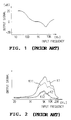
- In this type of tape reproducer, as shown in Fig. 1, sound leakage from the earphone can be prevented by suppressing high frequency sounds.
- However, as shown in Fig. 1, in case of suppressing only high frequency sounds, the deterioration in sound quality cannot be avoided. And accordingly, there occurs a problem, such as the music is unpleasant to the ear.
- And if the level of sound is increased excessively, sound leakage may occur accordingly.
- One of the methods to obviate such problems, as shown in Fig. 2, is to detect the level of sound (as shown characteristics K1 and K2) and to suppress the part where the level of sound is high (as shown characteristics K11 and K12).
- However, heretofore, even with this method the sound leakage could not be avoided perfectly. If the level of sound was increased in the tape reproducer proper, the sound leakage could not be avoided.
- In view of the foregoing, an object of this invention is to provide a reproducing device capable of preventing the decline in sound quality in advance and effectively avoiding the sound leakage from earphones.
- The foregoing object and other objects of the invention have been achieved by the provision of an audio signal reproducing device which comprises
amplifiers recording medium 6;earphones 28 and 30 for reproducing the output signals ofamplifiers level detection circuits earphones 28 and 30; andgain control circuits amplifiers - Regarding the input signals of the
earphones 28 and 30, the signal level of medium to high frequency is detected and when the sound volume of medium to high frequency sounds is high depending on the detected result thereof, the deterioration in sound quality can be effectively avoided and also sound leakage from earphones can be prevented by suppressing the signal level. - The nature, principle and utility of the invention will become more apparent from the following detailed description when read in conjunction with the accompanying drawings in which like parts are designated by like reference numerals or characters.
- In the accompanying drawings:
- Fig. 1 is a characteristic curvilinear diagram illustrating the prevention of sound leakage of the prior art;
- Fig.2 is a characteristic curvilinear diagram illustrating the other means for preventing sound leakage of the prior art.
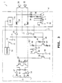
- Fig. 3 is a block diagram illustrating a tape reproducer according to one embodiment of the present invention;
- Fig. 4 is a characteristic curvilinear diagram showing its input/output characteristic; and
- Fig. 5 is a characteristic curvilinear diagram showing its frequency characteristic.
- Preferred embodiments of this invention will be described with reference to the accompanying drawings:
Designated generally at 1, in Fig. 3 is a tape reproducer, and the function of the tape reproducer 1 is changed by operating acontroller 4 which is connected to thetape reproducer body 2. - More specifically, in the tape reproducer
body 2, amagnetic tape 6 runs with the prescribed speed and the audio signal recorded on themagnetic tape 6 will be reproduced. - As a consequence, in the tape reproducer
body 2, reproducing signals to be obtained from themagnetic heads head amplifiers amplifiers level adjusting volumes controller 4. - In the
controller 4, the output signals ofamplifiers stereo type earphones 28 and 30 via sub soundlevel adjusting volumes - Thus, in the tape reproducer 1, music can be enjoyed with desired level of sound by adjusting the sound
level adjusting volumes level adjusting volumes controller 4 as occasion demands. - Furthermore, in the
controller 4, the input signals of theearphones 28 and 30 are added via the resistances 32 and 34, and supplied to the connecting point a of theslide switch 36. - Here, the
slide switch 36 is adapted to change the connecting point in three steps by slide operating the operation switch, and also to connect the connecting point a and b with theresistance 38, and to connect the connecting point c and d, and to earth the connecting point e. - Thus, the
slide switch 36 maintains the signal level of the output signal at the zero level by supplying the output signal of the connecting point c to the tape reproducerbody 2, on the condition that the connecting points c and e are short circuited; on the other hand, it feedbacks the input signals of theearphones 28 and 30 via theresistances 32, 34 and 38, on the condition that the connecting points b and d are short circuited. - Furthermore, the
slide switch 36 feedbacks the input signals of theearphones 28 and 30 to the tape reproducerbody 2 via the resistances 32 and 34 on the condition that the connecting points a and c are short circuited. - With this arrangement, in said tape reproducer 1, the signal level regarding the input signals of the
earphones 28 and 30 can be detected directly, and then the detected level can be changed by operating theslide switch 36. - In the tape reproducer
body 2, the output signal of theslide switch 36 is supplied to thetransistor 42 via thecapacitor 40 and is obtained upon suppressing the low-frequency range. - Here, the
transistor 42 is constituted by the emitter grounded circuit having theemitter resistance 43, and connects between the collector and the base with theresistance 44 and also the electric power source VCC will be supplied via thecollector resistance 46. - On the other hand, the
transistor 50 receives the collector output of thetransistor 42 upon suppressing the low-frequency range via thecapacitor 52, and said corrector output will be full-wave rectified at thediode 54 connected between the base and the emitter. - Accordingly, in the
transistor 50, regarding the input signals of theearphones 28 and 30, the signal level will be detected with medium to high frequency of higher than 1 [kHz]. - The
transistor 56 is adapted to input the collector output of thetransistor 50 to the base and also to ground the base at thecapacitor 58. - Moreover, the
transistor 56 is adapted to ground the emitter and also to connect the collector to thetransistors resistances - Here, the
transistors level adjusting volumes level adjusting volumes - Accordingly, in the tape reproducer 1, when the connecting points c and e are selected in the
slide switch 36, theearphones 28 and 30 will be actuated by the signal level determined at the soundlevel adjusting volumes level adjusting volumes - On the other hand, when the connecting points b and d are selected in the
slide switch 36, the input signals of theearphones 28 and 30 will be feedbacked as much level of feedbacks as determined by theresistances 34 and 38. And thetransistors earphones 28 and 30 will be suppressed depending on the sound level of medium to high frequency of the reproducing signal. Here the earphone output is controlled to not exceed 95 [dB] in signal level. - Furthermore, when the connecting points a and c are selected in the
slide switch 36, the input signals of theearphones 28 and 30 will be feed backed as much level of feedbacks as determined by the resistances 32 and 34, and accordingly, the sound level of theearphones 28 and 30 will be further suppressed as compared with the case of selecting the connecting points b and e. Here, the earphone output is controlled to not exceed 85 [dB] in signal level. - With this arrangement, in the tape reproducer 1, the sound leakage from the
earphones 28 and 30 can be effectively avoided by selecting the connecting point of theslide switch 36. - At this time, in the embodiment described above, in case of operating the
volumes body 2 side, the level of sound suppressing function can be steadily sustained by detecting the signal level directly regarding the input signals of theearphones 28 and 30, and thus the sound leakage can be prevented. - Moreover, the occurrence of the hearing disorders can be effectively avoided as well as preventing the sound leakage.
- Furthermore, at this time, the level of sound can be decreased without harming the frequency characteristic of reproducing signal by controlling the
transistors - Moreover, at this moment, regarding the input signals of the
earphones 28 and 30, even in case of reproducing with emphasis on low sounds, the level of sounds can be decreased only when necessary by the present invention relates to a reproducing device, e.g., in the portable tape reproducer, the deterioration in sound quality is prevented in advance and the sound leakage will be effectively avoided. - Moreover, at this moment, regarding the input signals of the
earphones 28 and 30, even in case of reproducing with emphasis on low sounds, the level of sounds can be decreased only when necessary by detecting the signal level of medium to high frequency sounds and suppressing the level of sounds. And accordingly, the usability of the tape reproducer 1 can be remarkably improved. - As shown in Figs. 4 and 5, according to an experiment, we confirmed that in case of suppressing the level of sound by operating the
slide switch 36, the deterioration in sound quality can be effectively avoided and thereby the level of sound can be suppressed. - Furthermore, according to the embodiment discussed above, since the
slide switch 36 for the level of sound suppressing is installed in thecontroller 4, operation can be switched easily at hand whenever necessary, and accordingly, the usability of the tape reproducer 1 can be improved. - Moreover, in the tape reproducer
body 2, the output signal of theslide switch 36 is transmitted to thetransistor 72 via theresistance 70 and thecapacitor 71, and thus the shifting information of theslide switch 36 will be supplied to thecontrol circuit 74 via thetransistor 72. - The
control circuit 74 shift controls the overall function of the tape reproducer 1 corresponding to the operation of, such as, a reproducing operation switch (not shown in Fig. 1) and drives a liquidcrystal display unit 75 which is installed in thecontroller 4, depending on the shifting information of theslide switch 36. - Thus, in the tape reproducer 1, the condition of the sound volume suppressing function can be confirmed by eye through the
controller 4, and the usability of the tape reproducer 1 can be improved. - According to the foregoing construction, the reproducing signals to be obtained from the
magnetic heads level adjusting volumes amplifiers earphones 28 and 30 via theamplifiers level adjusting volumes - At this time, the input signals of the
earphones 28 and 30 are supplied to thetransistor 42 via the resistances 32 and 34 and theslide switch 36, and after the low frequency range band is suppressed herein, full-wave rectified at thediode 54, then the signal level of medium to high frequency sounds will be detected via thetransistor 50. - The detected result of said signal level is supplied to the
transistors transistor 56 and thus the sound level of reproducing signal will be suppressed. - According to the foregoing construction, regarding the input signals of the
earphones 28 and 30, the signal level of medium to high frequency sounds will be detected directly and by suppressing the signal level of said input signals depending on the detected result thereof, the level of sound can be suppressed without fail effectively avoiding the deterioration in sound quality. - The embodiment discussed above has dealt with the case of applying the present invention to the tape reproducer equipped with the controller. However, the present invention is not only limited to the above, but also suitably applied to the tape reproducer which is adapted that the volume of sound can be adjusted only by the side of the tape reproducer body.
- Furthermore, the embodiment discussed above has dealt with the case of only suppressing the signal level. However, the present invention is not only limited to the above, but also frequency characteristic may be corrected at the same time.
- Moreover, the embodiment discussed above has dealt with the case of applying the present invention to the tape reproducers. However, the present invention is not only limited to the tape reproducers, but also widely applicable to the reproducing device which is adapted to test hearing by the earphone.
- According to the foregoing invention, regarding the input signals of the earphones, the reproducing device which is capable of preventing the sound leakage by effectively avoiding the deterioration in sound quality, can be obtained after directly detecting the signal level of medium to high frequency sounds and by suppressing the signal level depending on the detected result.
- While there has been described in connection with the preferred embodiments of the invention, it will be obvious to those skilled in the art that various changes and modification may be made therein without departing from the invention, and it is aimed, therefore, to cover in the appended claims all such changes and modifications as fall within the true spirit and scope of the invention.
Claims (5)
- An audio signal reproducing device, comprising:
an amplifier (12, 14; 20, 22) for amplifying reproducing signals to be obtained from a prescribed recording medium (6);
an earphone (28, 30) for reproducing output signals of said amplifier;
a signal level detection circuit (32-36) for detecting medium to high frequency sound signal level regarding input signals of said earphone; and
a signal level suppressing circuit (44-66) for suppressing the input signal of said earphone depending on the detected result of said signal level detection circuit, wherein:
said signal level suppressing circuit (44-66) suppresses the signal level of said input signal when medium to high frequency sound of said input signal is high. - The audio signal reproducing device according to claim 1, wherein said recording medium is a portable type tape reproducer (2).
- The audio signal reproducing device according to claim 1 or 2, wherein said signal level detection circuit includes a switch (36) having a plurality of contacts through which suppressing signals are feedbacked to said signal level suppressing circuit so as to suppress said input signal level corresponding to the switching positions of said switch (36).
- The audio signal reproducing device according to claim 3, wherein said switch (36) is a slide switch.
- The audio signal reproducing device according to claim 4, wherein said slide switch (36) has first contact for not suppressing said input signal level and second contact for suppressing said input signal level to a predetermined suppressing level.
Applications Claiming Priority (2)
| Application Number | Priority Date | Filing Date | Title |
|---|---|---|---|
| JP232403/91 | 1991-08-20 | ||
| JP3232403A JP3016446B2 (en) | 1991-08-20 | 1991-08-20 | Playback device |
Publications (3)
| Publication Number | Publication Date |
|---|---|
| EP0528404A2 true EP0528404A2 (en) | 1993-02-24 |
| EP0528404A3 EP0528404A3 (en) | 1995-01-18 |
| EP0528404B1 EP0528404B1 (en) | 1997-05-14 |
Family
ID=16938701
Family Applications (1)
| Application Number | Title | Priority Date | Filing Date |
|---|---|---|---|
| EP92114077A Expired - Lifetime EP0528404B1 (en) | 1991-08-20 | 1992-08-18 | Audio signal reproducing device |
Country Status (6)
| Country | Link |
|---|---|
| US (1) | US5537668A (en) |
| EP (1) | EP0528404B1 (en) |
| JP (1) | JP3016446B2 (en) |
| KR (1) | KR100240554B1 (en) |
| DE (1) | DE69219695T2 (en) |
| HK (1) | HK1006909A1 (en) |
Families Citing this family (11)
| Publication number | Priority date | Publication date | Assignee | Title |
|---|---|---|---|---|
| US6488097B1 (en) | 1999-01-08 | 2002-12-03 | Pnm, Inc. | Fire protection sprinkler head support |
| JP5396685B2 (en) | 2006-12-25 | 2014-01-22 | ソニー株式会社 | Audio output device, audio output method, audio output system, and audio output processing program |
| JP5401759B2 (en) | 2007-01-16 | 2014-01-29 | ソニー株式会社 | Audio output device, audio output method, audio output system, and audio output processing program |
| JP4640461B2 (en) | 2008-07-08 | 2011-03-02 | ソニー株式会社 | Volume control device and program |
| JP5482579B2 (en) * | 2010-09-02 | 2014-05-07 | ソニー株式会社 | Signal processing apparatus and method |
| US8831230B2 (en) * | 2011-04-15 | 2014-09-09 | Fairchild Semiconductor Corporation | Amplifier crosstalk cancellation technique |
| US10173088B2 (en) | 2014-05-28 | 2019-01-08 | The Reliable Automatic Sprinkler Co., Inc. | Bracket for installation of a fire protection sprinkler |
| MX364612B (en) | 2014-06-27 | 2019-05-02 | Anvil Int Llc | Adjustable bracket and hub for flexible hose support. |
| KR20160052405A (en) | 2014-10-31 | 2016-05-12 | 페어차일드 세미컨덕터 코포레이션 | Audio crosstalk calibration switch |
| US10015578B2 (en) | 2014-11-19 | 2018-07-03 | Fairchild Semiconductor Corporation | Remote ground sensing for reduced crosstalk of headset and microphone audio signals |
| JP7372548B2 (en) | 2020-04-02 | 2023-11-01 | 日本製鉄株式会社 | Coke oven furnace body tightening method and furnace clamping force transmission device |
Citations (4)
| Publication number | Priority date | Publication date | Assignee | Title |
|---|---|---|---|---|
| EP0036230A1 (en) * | 1980-03-18 | 1981-09-23 | Koninklijke Philips Electronics N.V. | MFB system with a by-pass network |
| DE3027953A1 (en) * | 1980-07-23 | 1982-02-25 | Zuch, Erhard H., 4930 Detmold | Frequency selection system for electroacoustical hearing aid - has parallel bandpass filters controlled automatically by analysis circuit with threshold switches |
| EP0410157A2 (en) * | 1983-06-03 | 1991-01-30 | THAT Corporation | Signal processing system for use with an audio reproduction system |
| EP0459506A1 (en) * | 1990-05-31 | 1991-12-04 | Sennheiser Electronic Kg | Volume limiting circuit |
Family Cites Families (5)
| Publication number | Priority date | Publication date | Assignee | Title |
|---|---|---|---|---|
| US3571529A (en) * | 1968-09-09 | 1971-03-16 | Zenith Radio Corp | Hearing aid with frequency-selective agc |
| JPS59108497A (en) * | 1982-12-14 | 1984-06-22 | Matsushita Electric Ind Co Ltd | Speaker protecting device |
| KR910007197B1 (en) * | 1988-08-23 | 1991-09-19 | 삼성전자 주식회사 | Remote controll circuit |
| JPH03297209A (en) * | 1990-04-16 | 1991-12-27 | Matsushita Electric Ind Co Ltd | Acoustic reproducing device |
| JP2897316B2 (en) * | 1990-02-23 | 1999-05-31 | ソニー株式会社 | Reproduction device and headphone device |
-
1991
- 1991-08-20 JP JP3232403A patent/JP3016446B2/en not_active Expired - Lifetime
-
1992
- 1992-08-18 EP EP92114077A patent/EP0528404B1/en not_active Expired - Lifetime
- 1992-08-18 DE DE69219695T patent/DE69219695T2/en not_active Expired - Lifetime
- 1992-08-20 KR KR1019920014953A patent/KR100240554B1/en not_active IP Right Cessation
-
1994
- 1994-10-27 US US08/330,225 patent/US5537668A/en not_active Expired - Lifetime
-
1998
- 1998-06-22 HK HK98105924A patent/HK1006909A1/en not_active IP Right Cessation
Patent Citations (4)
| Publication number | Priority date | Publication date | Assignee | Title |
|---|---|---|---|---|
| EP0036230A1 (en) * | 1980-03-18 | 1981-09-23 | Koninklijke Philips Electronics N.V. | MFB system with a by-pass network |
| DE3027953A1 (en) * | 1980-07-23 | 1982-02-25 | Zuch, Erhard H., 4930 Detmold | Frequency selection system for electroacoustical hearing aid - has parallel bandpass filters controlled automatically by analysis circuit with threshold switches |
| EP0410157A2 (en) * | 1983-06-03 | 1991-01-30 | THAT Corporation | Signal processing system for use with an audio reproduction system |
| EP0459506A1 (en) * | 1990-05-31 | 1991-12-04 | Sennheiser Electronic Kg | Volume limiting circuit |
Also Published As
| Publication number | Publication date |
|---|---|
| HK1006909A1 (en) | 1999-03-19 |
| DE69219695T2 (en) | 1997-09-04 |
| EP0528404B1 (en) | 1997-05-14 |
| US5537668A (en) | 1996-07-16 |
| EP0528404A3 (en) | 1995-01-18 |
| JPH0549091A (en) | 1993-02-26 |
| KR100240554B1 (en) | 2000-01-15 |
| KR930004992A (en) | 1993-03-23 |
| JP3016446B2 (en) | 2000-03-06 |
| DE69219695D1 (en) | 1997-06-19 |
Similar Documents
| Publication | Publication Date | Title |
|---|---|---|
| EP0528404B1 (en) | Audio signal reproducing device | |
| JPH0786857A (en) | Method and equipment to correspond and adjust sound volume of regerative apparatus for car to peripheral noise | |
| US5300892A (en) | Audio signal amplifier circuit | |
| US5323275A (en) | Digital signal recording and/or reproducing apparatus having correlated digital and analog signal level controllers | |
| US4504874A (en) | Tape recorder | |
| US6198586B1 (en) | Voice recording/playback apparatus for producing a noise level of a voice output unit in a voice recording mode | |
| JP3243737B2 (en) | Volume control circuit device | |
| KR0114190Y1 (en) | Automatic volume compensation circuit of portable acoustic machinery | |
| JPH0993063A (en) | Auto gain control circuit | |
| KR950013446B1 (en) | Audio recording/playing apparatus in a camcorder | |
| JP2690090B2 (en) | Tape recorder | |
| JP3423208B2 (en) | Recording / playback signal processing device | |
| JP2544441Y2 (en) | Small playback equipment | |
| KR910008984Y1 (en) | Audio recording control device by frequency | |
| JP2502086Y2 (en) | Sound reproduction device | |
| US4148081A (en) | Volume controlled tape end alarm for tape recorder | |
| JPS63281271A (en) | Noise reduction circuit | |
| JPH01151066A (en) | Tape recorder | |
| JP2715503B2 (en) | Cassette tape recorder | |
| US5856892A (en) | Recording apparatus with a control for selecting a gain adjustment amount | |
| JPS6112582Y2 (en) | ||
| JP2517856Y2 (en) | Howling prevention circuit of tape recorder | |
| JP3365019B2 (en) | Recording device | |
| JP3162869B2 (en) | Noise reduction circuit of recording / reproducing device | |
| JPH0470098A (en) | Acoustic device with heavy and low sound increasing function |
Legal Events
| Date | Code | Title | Description |
|---|---|---|---|
| PUAI | Public reference made under article 153(3) epc to a published international application that has entered the european phase |
Free format text: ORIGINAL CODE: 0009012 |
|
| AK | Designated contracting states |
Kind code of ref document: A2 Designated state(s): DE FR GB |
|
| PUAL | Search report despatched |
Free format text: ORIGINAL CODE: 0009013 |
|
| AK | Designated contracting states |
Kind code of ref document: A3 Designated state(s): DE FR GB |
|
| 17P | Request for examination filed |
Effective date: 19950705 |
|
| GRAG | Despatch of communication of intention to grant |
Free format text: ORIGINAL CODE: EPIDOS AGRA |
|
| 17Q | First examination report despatched |
Effective date: 19960731 |
|
| GRAH | Despatch of communication of intention to grant a patent |
Free format text: ORIGINAL CODE: EPIDOS IGRA |
|
| GRAH | Despatch of communication of intention to grant a patent |
Free format text: ORIGINAL CODE: EPIDOS IGRA |
|
| GRAA | (expected) grant |
Free format text: ORIGINAL CODE: 0009210 |
|
| AK | Designated contracting states |
Kind code of ref document: B1 Designated state(s): DE FR GB |
|
| REF | Corresponds to: |
Ref document number: 69219695 Country of ref document: DE Date of ref document: 19970619 |
|
| ET | Fr: translation filed | ||
| PLBE | No opposition filed within time limit |
Free format text: ORIGINAL CODE: 0009261 |
|
| STAA | Information on the status of an ep patent application or granted ep patent |
Free format text: STATUS: NO OPPOSITION FILED WITHIN TIME LIMIT |
|
| 26N | No opposition filed | ||
| REG | Reference to a national code |
Ref country code: GB Ref legal event code: IF02 |
|
| PGFP | Annual fee paid to national office [announced via postgrant information from national office to epo] |
Ref country code: GB Payment date: 20110819 Year of fee payment: 20 Ref country code: DE Payment date: 20110823 Year of fee payment: 20 Ref country code: FR Payment date: 20110901 Year of fee payment: 20 |
|
| REG | Reference to a national code |
Ref country code: DE Ref legal event code: R071 Ref document number: 69219695 Country of ref document: DE |
|
| REG | Reference to a national code |
Ref country code: DE Ref legal event code: R071 Ref document number: 69219695 Country of ref document: DE |
|
| REG | Reference to a national code |
Ref country code: GB Ref legal event code: PE20 Expiry date: 20120817 |
|
| PG25 | Lapsed in a contracting state [announced via postgrant information from national office to epo] |
Ref country code: DE Free format text: LAPSE BECAUSE OF EXPIRATION OF PROTECTION Effective date: 20120821 Ref country code: GB Free format text: LAPSE BECAUSE OF EXPIRATION OF PROTECTION Effective date: 20120817 |