EP0528261A1 - Arrangement with a branch fitting - Google Patents
Arrangement with a branch fitting Download PDFInfo
- Publication number
- EP0528261A1 EP0528261A1 EP92113294A EP92113294A EP0528261A1 EP 0528261 A1 EP0528261 A1 EP 0528261A1 EP 92113294 A EP92113294 A EP 92113294A EP 92113294 A EP92113294 A EP 92113294A EP 0528261 A1 EP0528261 A1 EP 0528261A1
- Authority
- EP
- European Patent Office
- Prior art keywords
- nozzle
- heating coil
- spigot
- collar
- centering
- Prior art date
- Legal status (The legal status is an assumption and is not a legal conclusion. Google has not performed a legal analysis and makes no representation as to the accuracy of the status listed.)
- Granted
Links
Images
Classifications
-
- B—PERFORMING OPERATIONS; TRANSPORTING
- B29—WORKING OF PLASTICS; WORKING OF SUBSTANCES IN A PLASTIC STATE IN GENERAL
- B29C—SHAPING OR JOINING OF PLASTICS; SHAPING OF MATERIAL IN A PLASTIC STATE, NOT OTHERWISE PROVIDED FOR; AFTER-TREATMENT OF THE SHAPED PRODUCTS, e.g. REPAIRING
- B29C65/00—Joining or sealing of preformed parts, e.g. welding of plastics materials; Apparatus therefor
- B29C65/02—Joining or sealing of preformed parts, e.g. welding of plastics materials; Apparatus therefor by heating, with or without pressure
- B29C65/34—Joining or sealing of preformed parts, e.g. welding of plastics materials; Apparatus therefor by heating, with or without pressure using heated elements which remain in the joint, e.g. "verlorenes Schweisselement"
- B29C65/3404—Joining or sealing of preformed parts, e.g. welding of plastics materials; Apparatus therefor by heating, with or without pressure using heated elements which remain in the joint, e.g. "verlorenes Schweisselement" characterised by the type of heated elements which remain in the joint
- B29C65/342—Joining or sealing of preformed parts, e.g. welding of plastics materials; Apparatus therefor by heating, with or without pressure using heated elements which remain in the joint, e.g. "verlorenes Schweisselement" characterised by the type of heated elements which remain in the joint comprising at least a single wire, e.g. in the form of a winding
-
- B—PERFORMING OPERATIONS; TRANSPORTING
- B29—WORKING OF PLASTICS; WORKING OF SUBSTANCES IN A PLASTIC STATE IN GENERAL
- B29C—SHAPING OR JOINING OF PLASTICS; SHAPING OF MATERIAL IN A PLASTIC STATE, NOT OTHERWISE PROVIDED FOR; AFTER-TREATMENT OF THE SHAPED PRODUCTS, e.g. REPAIRING
- B29C65/00—Joining or sealing of preformed parts, e.g. welding of plastics materials; Apparatus therefor
- B29C65/02—Joining or sealing of preformed parts, e.g. welding of plastics materials; Apparatus therefor by heating, with or without pressure
- B29C65/34—Joining or sealing of preformed parts, e.g. welding of plastics materials; Apparatus therefor by heating, with or without pressure using heated elements which remain in the joint, e.g. "verlorenes Schweisselement"
- B29C65/3472—Joining or sealing of preformed parts, e.g. welding of plastics materials; Apparatus therefor by heating, with or without pressure using heated elements which remain in the joint, e.g. "verlorenes Schweisselement" characterised by the composition of the heated elements which remain in the joint
- B29C65/3476—Joining or sealing of preformed parts, e.g. welding of plastics materials; Apparatus therefor by heating, with or without pressure using heated elements which remain in the joint, e.g. "verlorenes Schweisselement" characterised by the composition of the heated elements which remain in the joint being metallic
-
- B—PERFORMING OPERATIONS; TRANSPORTING
- B29—WORKING OF PLASTICS; WORKING OF SUBSTANCES IN A PLASTIC STATE IN GENERAL
- B29C—SHAPING OR JOINING OF PLASTICS; SHAPING OF MATERIAL IN A PLASTIC STATE, NOT OTHERWISE PROVIDED FOR; AFTER-TREATMENT OF THE SHAPED PRODUCTS, e.g. REPAIRING
- B29C66/00—General aspects of processes or apparatus for joining preformed parts
- B29C66/01—General aspects dealing with the joint area or with the area to be joined
- B29C66/05—Particular design of joint configurations
- B29C66/10—Particular design of joint configurations particular design of the joint cross-sections
- B29C66/11—Joint cross-sections comprising a single joint-segment, i.e. one of the parts to be joined comprising a single joint-segment in the joint cross-section
- B29C66/112—Single lapped joints
-
- B—PERFORMING OPERATIONS; TRANSPORTING
- B29—WORKING OF PLASTICS; WORKING OF SUBSTANCES IN A PLASTIC STATE IN GENERAL
- B29C—SHAPING OR JOINING OF PLASTICS; SHAPING OF MATERIAL IN A PLASTIC STATE, NOT OTHERWISE PROVIDED FOR; AFTER-TREATMENT OF THE SHAPED PRODUCTS, e.g. REPAIRING
- B29C66/00—General aspects of processes or apparatus for joining preformed parts
- B29C66/01—General aspects dealing with the joint area or with the area to be joined
- B29C66/05—Particular design of joint configurations
- B29C66/10—Particular design of joint configurations particular design of the joint cross-sections
- B29C66/13—Single flanged joints; Fin-type joints; Single hem joints; Edge joints; Interpenetrating fingered joints; Other specific particular designs of joint cross-sections not provided for in groups B29C66/11 - B29C66/12
- B29C66/131—Single flanged joints, i.e. one of the parts to be joined being rigid and flanged in the joint area
- B29C66/1312—Single flange to flange joints, the parts to be joined being rigid
-
- B—PERFORMING OPERATIONS; TRANSPORTING
- B29—WORKING OF PLASTICS; WORKING OF SUBSTANCES IN A PLASTIC STATE IN GENERAL
- B29C—SHAPING OR JOINING OF PLASTICS; SHAPING OF MATERIAL IN A PLASTIC STATE, NOT OTHERWISE PROVIDED FOR; AFTER-TREATMENT OF THE SHAPED PRODUCTS, e.g. REPAIRING
- B29C66/00—General aspects of processes or apparatus for joining preformed parts
- B29C66/50—General aspects of joining tubular articles; General aspects of joining long products, i.e. bars or profiled elements; General aspects of joining single elements to tubular articles, hollow articles or bars; General aspects of joining several hollow-preforms to form hollow or tubular articles
- B29C66/51—Joining tubular articles, profiled elements or bars; Joining single elements to tubular articles, hollow articles or bars; Joining several hollow-preforms to form hollow or tubular articles
- B29C66/52—Joining tubular articles, bars or profiled elements
- B29C66/522—Joining tubular articles
- B29C66/5224—Joining tubular articles for forming fork-shaped connections, e.g. for making Y-shaped pieces
- B29C66/52241—Joining tubular articles for forming fork-shaped connections, e.g. for making Y-shaped pieces with two right angles, e.g. for making T-shaped pieces
-
- B—PERFORMING OPERATIONS; TRANSPORTING
- B29—WORKING OF PLASTICS; WORKING OF SUBSTANCES IN A PLASTIC STATE IN GENERAL
- B29C—SHAPING OR JOINING OF PLASTICS; SHAPING OF MATERIAL IN A PLASTIC STATE, NOT OTHERWISE PROVIDED FOR; AFTER-TREATMENT OF THE SHAPED PRODUCTS, e.g. REPAIRING
- B29C66/00—General aspects of processes or apparatus for joining preformed parts
- B29C66/50—General aspects of joining tubular articles; General aspects of joining long products, i.e. bars or profiled elements; General aspects of joining single elements to tubular articles, hollow articles or bars; General aspects of joining several hollow-preforms to form hollow or tubular articles
- B29C66/51—Joining tubular articles, profiled elements or bars; Joining single elements to tubular articles, hollow articles or bars; Joining several hollow-preforms to form hollow or tubular articles
- B29C66/52—Joining tubular articles, bars or profiled elements
- B29C66/522—Joining tubular articles
- B29C66/5229—Joining tubular articles involving the use of a socket
- B29C66/52298—Joining tubular articles involving the use of a socket said socket being composed by several elements
-
- F—MECHANICAL ENGINEERING; LIGHTING; HEATING; WEAPONS; BLASTING
- F16—ENGINEERING ELEMENTS AND UNITS; GENERAL MEASURES FOR PRODUCING AND MAINTAINING EFFECTIVE FUNCTIONING OF MACHINES OR INSTALLATIONS; THERMAL INSULATION IN GENERAL
- F16L—PIPES; JOINTS OR FITTINGS FOR PIPES; SUPPORTS FOR PIPES, CABLES OR PROTECTIVE TUBING; MEANS FOR THERMAL INSULATION IN GENERAL
- F16L47/00—Connecting arrangements or other fittings specially adapted to be made of plastics or to be used with pipes made of plastics
- F16L47/02—Welded joints; Adhesive joints
- F16L47/03—Welded joints with an electrical resistance incorporated in the joint
-
- F—MECHANICAL ENGINEERING; LIGHTING; HEATING; WEAPONS; BLASTING
- F16—ENGINEERING ELEMENTS AND UNITS; GENERAL MEASURES FOR PRODUCING AND MAINTAINING EFFECTIVE FUNCTIONING OF MACHINES OR INSTALLATIONS; THERMAL INSULATION IN GENERAL
- F16L—PIPES; JOINTS OR FITTINGS FOR PIPES; SUPPORTS FOR PIPES, CABLES OR PROTECTIVE TUBING; MEANS FOR THERMAL INSULATION IN GENERAL
- F16L47/00—Connecting arrangements or other fittings specially adapted to be made of plastics or to be used with pipes made of plastics
- F16L47/26—Connecting arrangements or other fittings specially adapted to be made of plastics or to be used with pipes made of plastics for branching pipes; for joining pipes to walls; Adaptors therefor
- F16L47/32—Branch units, e.g. made in one piece, welded, riveted
Definitions
- the invention relates to a nozzle fitting according to the features specified in the preamble of claim 1.
- EP 378 406 A2 discloses such a nozzle fitting, the heating coil of which is not arranged in the inner surface of the nozzle, but rather within a non-crosslinked layer.
- this nozzle fitting is made of cross-linked polyolefin, so that the required dimensional stability is maintained even when exposed to hot water.
- the heating coil In special process steps, the heating coil must first be introduced into the non-crosslinked layer and enclosed by it.
- the arrangement of the non-crosslinked layer together with the heating coil in the nozzle requires additional manufacturing effort and further measures for aligning and defining this non-crosslinked layer in the nozzle are required. There is a risk that the layer with the heating winding will be loosened from the annular groove or undercut of the nozzle or that a leak will occur. It is not clear what means are used to drill the pipe to be connected to the nozzle fitting.
- a tapping fitting is known from DE 38 30 395 C1, which is designed as a saddle piece and contains the heating coil on the inner surface of a first half-shell for connection to the outer surface of the pipe.
- a second half-shell and corresponding screws or other connecting elements are used to fix it on the outer surface of the pipe.
- the nozzle which is attached orthogonally to the pipe, is used to fasten a tapping device that contains a drill for drilling the pipe. After drilling has been completed, the drill is moved back into the socket in order to clear the path from the inner socket part into a connection socket arranged orthogonally to the socket and from there into the connected branch line.
- the nozzle has a comparatively large overall height and does not allow a branch line to be connected directly. If this fitting is installed with the pipeline in the floor, the socket is regularly aligned vertically and the connection piece horizontally. If construction work is required in the area of the pipeline or on it, there is a considerable risk that, in practice, in particular with an excavator, the connecting piece projecting vertically upwards will be caught and considerable damage will be caused.
- a plug setting device which has an external thread at the lower end of its housing.
- the plug-in tool is screwed with the mentioned external thread into an assigned internal thread of a gate valve, which has a second internal thread opposite.
- the locking slide is screwed onto an external thread of a pipe attachment via this internal thread.
- a tapping device can be screwed into the locking slide as required to prepare the pipe for inserting the plug.
- the aim of the known plug setting device is to close a hole in the pipeline, while the present nozzle fitting is to be designed to connect a branch line.
- the invention has for its object to develop the nozzle fitting of the type mentioned with little design effort so that with a reduced external dimensions, a branch line can be easily connected.
- the nozzle fitting should require a small amount of material and weight and should enable the establishment of a functionally reliable connection between the pipeline and the branch line. Handling during assembly should be made easier, the number of components and the risk of damage reduced.
- the proposed connector fitting is characterized by a functionally reliable construction by small external dimensions and enables the direct connection of a branch line to the connector.
- the medium is deflected from the direction of the pipe longitudinal axis in the direction of the nozzle axis, which is preferably arranged orthogonally, with only a few components and with little manufacturing effort.
- the nozzle fitting has compact external dimensions and enables easy handling during assembly and the work required to connect a branch line to the pipeline.
- the socket contains a heating coil directly in its inner surface, which enables a functionally reliable and direct connection to the branch line. No additional layer is required for the heating coil and the nozzle is made of the same material throughout with a comparatively small wall thickness.
- the heating coil is embedded in the inner surface of the nozzle and stands when welding in direct contact with the outer surface of the pipe or the branch line.
- the nozzle length is reduced to a minimum, especially since the end of the heating coil or welding winding facing the pipe longitudinal axis can reach the outer apex of the half-shell or the saddle, taking into account a cold zone which is expediently to be observed for welding.
- the socket expediently has a centering surface for a tapping device on the outside.
- Said centering collar can in particular contain a connecting thread for the tapping device and / or a centering or stop surface, so that the tapping device can be attached to the nozzle fitting in alignment with the nozzle axis.
- This nozzle fitting enables the production of large tapping diameters in a particularly expedient manner, so that flow losses between the pipeline and the branch line are reduced to a minimum.
- the nozzle fitting enables user-friendly assembly and processing on the construction site, whereby only a few simple auxiliary tools are required for processing.
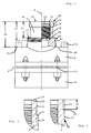
- Fig. 1 shows the nozzle fitting with a saddle piece 2 and a nozzle 4, the axis 6 of which is orthogonal to the longitudinal axis 8 of a pipe (not shown here).
- the saddle piece 2 and the socket 4 form a one-piece shaped piece, a heating coil for welding to the tube mentioned being provided in a known manner on the inner surface of the saddle piece 2.
- the saddle piece 2 is formed from a half shell and, together with a second half shell 10 and screws 12, this nozzle fitting can be fixed on the outer surface of the tube.
- the saddle piece 2 contains two sockets 14, 15, into which the ends of the heating coil are guided in order to be able to establish the electrical connection to a welding device by means of plugs.
- the connecting piece 4 serves for the direct connection of a branch line coaxial to the connecting piece axis 6.
- the connecting piece 4 is designed as an electric welding sleeve which contains a heating coil 16 inside and into which the pipe end of the branch line can be inserted directly.
- the heating coil 16 is embedded directly in the inner surface 17 of the connector 4 and, when welded to the branch line, lies directly against the outer surface thereof.
- the socket and the saddle are formed in one piece and consist of the same weldable plastic in which the heating coil 16 is directly embedded without additional intermediate layers or the like.
- the nozzle 4 can have a comparatively small wall thickness, which not inconsiderable material and weight savings are made possible.
- the socket 4 has an inner collar 18 as a stop, especially for a protective tube used when drilling and also for the tube end to be inserted.
- the nozzle 4 ends in a flat end face 19, which is expediently arranged in a radial plane with respect to the nozzle axis 6.
- the nozzle 4 has a height 20 in the direction of the nozzle axis 6, which is substantially smaller than the height of previously known nozzle fittings or tapping fittings.
- the height 20 is essentially the same size as the required axial length of the heating coil 16 additionally at the ends of the cold zones 22, 24, which are expediently provided for proper welding.
- the inner ring collar 18 is arranged at a depth 21 from the end face 19 and this depth is less than the height 20 of the nozzle 4.
- the heating coil 16 ends in the direction of the longitudinal axis 8 near the apex line 26 of the saddle piece 2.
- the annular collar 18 is preferably arranged.
- the socket 4 has a centering collar 28 on the outside, which here has an external thread 30 for immediate screwing contains a tapping device.
- the centering collar 28 is used for the coaxial alignment of a tapping device with which, after the nozzle fitting has been welded onto the pipe, the latter can be drilled out.
- the centering collar 28 has a stop surface 27 which, like the end surface 19, lies in a radial plane with respect to the nozzle axis 6.
- the stop surface 27 is at a distance 31 from the end face 19, which is smaller than the depth 21 from the inner ring collar 18.
- the outer ring collar 28 serves to center the tapping device, which is thus reliably coaxially aligned with the nozzle axis 6, so that damage to the direct heating coil 16 embedded in the inner surface is reliably avoided, in particular by the drill of the tapping device.
- the pipeline may also contain the pressurized medium, in particular natural gas or water, the undesired outflow of the medium being prevented in a known manner by additional shut-off elements.
- a centering collar with a corresponding centering surface can generally be provided on the outside of the connection piece 4, with the attachment of the tapping device using straps. It goes without saying that the external thread or centering surfaces or the like correspond to associated threads or surfaces of the drilling device, so that the required coaxial alignment of the drilling device with respect to the connection piece 4 is ensured.
- the connector 4 has in the area of the axial end face 19 an additional centering collar 29 and / or a centering surface 33 for the drilling device mentioned.
- This centering collar 29 is axially spaced from the other centering collar 28 and / or the external thread 30, so that overall a very exact coaxial alignment of the tapping device with respect to the nozzle axis 6 is ensured.
- the described external thread 30 does not necessarily have to be part of a centering collar for fastening the tapping device be, especially since the axial spacing between the centering collar on the one hand and the external thread 30 on the other hand enables a very exact alignment.
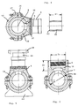
- FIG. 2 and 3 show configurations of the centering collar 28 with the associated external thread 30.
- the external thread 30 is provided at the free end 32 of the connecting piece 4.
- the external thread 30 has a thread length 35 which is predetermined such that the tapping device can be firmly connected to the nozzle 4.
- the axially adjoining centering surface 33 ensures the exact coaxial alignment.
- the external thread 30 can directly form the centering surface, the alignment of the tapping device aligned with the nozzle axis 6 being achieved in cooperation with the stop surface 27.
- the external thread 30 begins approximately in the middle of the length of the connecting piece 4 relating to the aforementioned apex line and extends in the direction of the saddle piece 2 (not shown further here).
- the cylindrical outer surface in the region of the free end 32 is additionally used as centering surface 33 for the tapping device.
- Fig. 4 shows the nozzle fitting in the normal installation position, in which the nozzle 4 is arranged horizontally.
- the nozzle axis 6 and the longitudinal axis 8 of the tube 34 lie in the same horizontal plane.
- the medium flowing through the tube 34 reaches the branch line welded coaxially to the nozzle axis 6 in the nozzle 4 with only a single deflection by 90 °.
- the branch line is thus in the same horizontal plane as the pipe 34 or the pipe from which the medium flows into the branch line.
- the bore 38 can be seen, which has been introduced into the tube 34 by means of the aforementioned drilling device. So that the heating coil lying in the inner surface of the connection piece 4 is not damaged during drilling, a short protective tube 40 is inserted into the connection piece 4 before the drilling device is screwed onto the external thread 30.
- This protective tube 40 has a length 41 which is at least substantially the same size as the depth 21. The axial end face 42 of the protective tube is brought into contact with the already mentioned collar inside the connecting piece 4.
- the length 41 is at least approximately the same as the depth 21 and preferably can also be longer and thus the protective tube 40 protrudes beyond the end face 19, the correct fit of the protective tube 40 can be checked in a simple manner on the one hand and damage to the in the The inner surface of the heating coil, which is at least partially exposed, is functionally prevented by the drill of the tapping device. After the bore 38 has been drilled into the tube 34, the protective tube 40 and the tapping device are withdrawn from the nozzle 4, so that the tube end of the branch line can subsequently be inserted into the nozzle 4 and welded by means of the heating coil which has remained undamaged.
- FIG. 5 shows a special embodiment of the nozzle fitting, according to which the second half-shell has a base plate 44 for forming a hydrant foot.
- the connecting piece 4 is oriented vertically and in it a connector 46 with a flange 48 corresponding to the above-described pipe end is firmly connected by welding from the branch line.
- a hydrant can easily be connected to the flange 48. It is also decisive in this embodiment that the medium flowing through the tube 34 is deflected only once and the connecting part 46 is aligned coaxially with the nozzle axis 6.
- the embodiment of the nozzle fitting shown in Fig. 6 enables the connection of branch lines with the same pipe diameter as the pipe 34.
- the heating coil 16 extends into the plane of the apex line 26 of the outer surface of the saddle piece 2.
- the inner diameter 50 of the nozzle 4 or the there provided heating coil 6 corresponds, taking into account the usual tolerances, the outer diameter 52 of the tube 34.
- the height 20 of the connector 4 is very low in comparison with previously known fittings, in which the branch line is orthogonal to the connector.
- the annular collar 18 serving as a stop for the pipe end to be inserted lies in this embodiment in the plane in which the apex line 26 extends.
Landscapes
- Engineering & Computer Science (AREA)
- Mechanical Engineering (AREA)
- General Engineering & Computer Science (AREA)
- Branch Pipes, Bends, And The Like (AREA)
- Lining Or Joining Of Plastics Or The Like (AREA)
- Nozzles (AREA)
- Joints Allowing Movement (AREA)
- Infusion, Injection, And Reservoir Apparatuses (AREA)
- Prostheses (AREA)
Abstract
Description
Die Erfindung bezieht sich auf eine Stutzenarmatur gemäß den im Oberbegriff des Patentanspruchs 1 angegebenen Merkmalen.The invention relates to a nozzle fitting according to the features specified in the preamble of claim 1.
Aus der EP 378 406 A2 ist eine derartige Stutzenarmatur bekannt, deren Heizwendel nicht in der Innenfläche des Stutzens, sondern innerhalb einer nicht vernetzten Schicht angeordnet ist. Im übrigen besteht diese Stutzenarmatur aus vernetztem Polyolefin, damit auch beim Einwirken von heißem Wasser eine geforderte Formbeständigkeit eingehalten wird. In besonderen Verfahrensschritten muß die Heizwendel zunächst in die nicht vernetzte Schicht eingebracht und von dieser umschlossen werden. Des weiteren erfordert die Anordnung der nicht vernetzten Schicht zusammen mit der Heizwendel in dem Stutzen einen zusätzlichen Fertigungsaufwand und es sind weitere Maßnahmen zur Ausrichtung und definierten Festlegung dieser nicht vernetzten Schicht im Stutzen erforderlich. Es besteht die Gefahr, daß die Schicht mit der Heizwicklung aus der Ringnut oder Hinterschneidung des Stutzens gelöst wird oder insoweit eine Undichtigkeit eintritt. Es ist nicht ersichtlich, mit welchen Mitteln das mit der Stutzenarmatur zu verbindende Rohr anzubohren ist.EP 378 406 A2 discloses such a nozzle fitting, the heating coil of which is not arranged in the inner surface of the nozzle, but rather within a non-crosslinked layer. In addition, this nozzle fitting is made of cross-linked polyolefin, so that the required dimensional stability is maintained even when exposed to hot water. In special process steps, the heating coil must first be introduced into the non-crosslinked layer and enclosed by it. Furthermore, the arrangement of the non-crosslinked layer together with the heating coil in the nozzle requires additional manufacturing effort and further measures for aligning and defining this non-crosslinked layer in the nozzle are required. There is a risk that the layer with the heating winding will be loosened from the annular groove or undercut of the nozzle or that a leak will occur. It is not clear what means are used to drill the pipe to be connected to the nozzle fitting.
Ferner ist aus der DE 38 30 395 C1 eine Anbohrarmatur bekannt, welche als Sattelstück ausgebildet ist und auf der Innenfläche einer ersten Halbschale die Heizwendel zur Verbindung mit der Rohraußenfläche enthält. Vor dem Schweißen erfolgt eine Festlegung mittels einer zweiten Halbschale und entsprechenden Schrauben oder sonstigen Verbindungselementen auf der Rohraußenfläche. Der zum Rohr orthogonal angebrachte Stutzen dient zur Befestigung eines Anbohrgerätes, welches einen Bohrer zum Anbohren des Rohres enthält. Nach erfolgter Anbohrung wird der Bohrer in den Stutzen zurückbewegt, um den Weg vom inneren Stutzenteil in einen orthogonal zum Stutzen angeordneten Anschlußstutzen und von dort in die angeschlossene Abzweigleitung freizugeben. Es erfolgt eine doppelte Umlenkung des Mediums, und zwar zunächst orthogonal zur Längsachse der Rohrleitung radial nach außen in den Stutzen und von dort orthogonal zur Längsachse des Stutzens in den Anschlußstutzen. Der Stutzen weist insgesamt eine vergleichsweise große Bauhöhe auf und ermöglicht keinen direkten Anschluß einer Abzweigleitung. Ist diese Armatur mit der Rohrleitung im Boden verlegt, so ist der Stutzen regelmäßig vertikal und der Anschlußstutzen horizontal ausgerichtet. Werden im Bereich der Rohrleitung oder an dieser Baumaßnahmen erforderlich, so besteht das erhebliche Risiko, daß in der Praxis, insbesondere mit einem Bagger, der vertikal nach oben abstehende Stutzen erfaßt wird und erhebliche Schäden verursacht werden.Furthermore, a tapping fitting is known from
Schließlich ist aus der DE 88 12 134 U1 ein Stopfensetzgerät bekannt, welches am unteren Ende seines Gehäuses ein Außengewinde aufweist. Das Stopfensetzgerät wird mit dem genannten Außengewinde in ein zugeordnetes Innengewinde eines Sperrschiebers geschraubt, welcher gegenüberliegend ein zweites Innengewinde besitzt. Über dieses Innengewinde wird der Sperrschieber auf ein Außengewinde eines Rohransatzes geschraubt. Anstelle des Stopfensetzgerätes kann in den genannten Sperrschieber bedarfsweise ein Anbohrgerät geschraubt werden, um das Rohr für das Einsetzen des Stopfens vorzubereiten. Zielsetzung des bekannten Stopfensetzgerätes ist es, ein Loch der Rohrleitung zu verschließen, während die vorliegende Stutzenarmatur zum Anschluß einer Abzweigleitung auszubilden ist.Finally, from DE 88 12 134 U1 a plug setting device is known which has an external thread at the lower end of its housing. The plug-in tool is screwed with the mentioned external thread into an assigned internal thread of a gate valve, which has a second internal thread opposite. The locking slide is screwed onto an external thread of a pipe attachment via this internal thread. Instead of the plug-in tool, a tapping device can be screwed into the locking slide as required to prepare the pipe for inserting the plug. The aim of the known plug setting device is to close a hole in the pipeline, while the present nozzle fitting is to be designed to connect a branch line.
Daher liegt der Erfindung die Aufgabe zugrunde, die Stutzenarmatur der genannten Art mit geringem konstruktiven Aufwand dahingehend weiterzubilden, daß bei reduzierten Außenabmessungen ein problemloser Anschluß einer Abzweigleitung erfolgen kann. Die Stutzenarmatur soll einen geringen Material-und Gewichtsbedarf erfordern und die Herstellung einer funktionssicheren Verbindung zwischen der Rohrleitung und der Abzweigleitung ermöglichen. Die Handhabung bei der Montage soll erleichtert, die Anzahl der Bauteile und die Gefahr von Beschädigungen reduziert werden.Therefore, the invention has for its object to develop the nozzle fitting of the type mentioned with little design effort so that with a reduced external dimensions, a branch line can be easily connected. The nozzle fitting should require a small amount of material and weight and should enable the establishment of a functionally reliable connection between the pipeline and the branch line. Handling during assembly should be made easier, the number of components and the risk of damage reduced.
Die Lösung dieser Aufgabe erfolgt nach den kennzeichnenden Merkmalen des Patentanspruchs 1.This object is achieved according to the characterizing features of patent claim 1.
Die vorgeschlagene Stutzenarmatur zeichnet sich bei funktionssicherer Konstruktion durch geringe Außenabmessungen aus und ermöglicht den direkten Anschluß einer Abzweigleitung an den Stutzen. Es erfolgt hierbei mit wenigen Bauteilen und mit geringem Fertigungsaufwand nur eine einmalige Umlenkung des Mediums aus der Richtung der Rohrlängsachse in Richtung der bevorzugt orthogonal hierzu angeordneten Stutzenachse. Die Stutzenarmatur weist kompakte Außenabmessungen auf und ermöglicht eine einfache Handhabung bei der Montage und den erforderlichen Arbeiten zum Anschluß einer Abzweigleitung an die Rohrleitung. Der Stutzen enthält direkt in seiner Innenfläche eine Heizwendel, welche eine funktionssichere und unmittelbare Verbindung mit der Abzweigleitung ermöglicht. Für die Heizwendel ist keine zusätzliche Schicht erforderlich und der Stutzen besteht durchgehend bei vergleichsweise kleiner Wandstärke aus dem gleichen Werkstoff. Die Heizwendel ist in die Innenfläche des Stutzens eingebettet und steht beim Schweißen in unmittelbarem Kontakt mit der Außenfläche des Rohres bzw. der Abzweigleitung. Die Stutzenlänge ist auf ein Minimum reduziert, zumal das der Rohrlängsachse zugewandte Ende der Heizwendel- oder Schweißwicklung unter Berücksichtigung einer zum Schweißen in zweckmäßiger Weise einzuhaltenden kalten Zone bis an den äußeren Scheitel der Halbschale oder des Sattelstücks heranreichen kann. Der Stutzen weist in zweckmäßiger Weise außen eine Zentrierfläche für ein Anbohrgerät auf.The proposed connector fitting is characterized by a functionally reliable construction by small external dimensions and enables the direct connection of a branch line to the connector. In this case, the medium is deflected from the direction of the pipe longitudinal axis in the direction of the nozzle axis, which is preferably arranged orthogonally, with only a few components and with little manufacturing effort. The nozzle fitting has compact external dimensions and enables easy handling during assembly and the work required to connect a branch line to the pipeline. The socket contains a heating coil directly in its inner surface, which enables a functionally reliable and direct connection to the branch line. No additional layer is required for the heating coil and the nozzle is made of the same material throughout with a comparatively small wall thickness. The heating coil is embedded in the inner surface of the nozzle and stands when welding in direct contact with the outer surface of the pipe or the branch line. The nozzle length is reduced to a minimum, especially since the end of the heating coil or welding winding facing the pipe longitudinal axis can reach the outer apex of the half-shell or the saddle, taking into account a cold zone which is expediently to be observed for welding. The socket expediently has a centering surface for a tapping device on the outside.
Mit der Zentrierfläche, welche insbesondere Bestandteil eines Zentrierbundes ist, wird eine exakte Ausrichtung des Anbohrgerätes auf dem Stutzen sichergestellt, um eine Beschädigung der in der Innenfläche des Stutzens weitgehend freiliegenden Heizwendel durch den Bohrer sicher zu verhindern. Es wird somit vermieden, daß infolge einer Beschädigung der Heizwendel die Schweißverbindung mit der Abzweigleitung fehlerhaft wird, zumal derartige Fehler oftmals nicht unmittelbar nach der Herstellung der Verbindung, sondern erst nach gewisser Zeit nach außen hin in Erscheinung treten, wenn die Rohrleitung insbesondere im Erdreich verlegt ist. Aufgrund der exakten Ausrichtung des Anbohrgerätes über den Zentrierbund werden derartige Spätschäden, welche nur mit einem erheblichen Aufwand beseitigt werden können, mit hoher Sicherheit vermieden.With the centering surface, which is in particular a component of a centering collar, an exact alignment of the tapping device on the nozzle is ensured in order to reliably prevent damage to the heating coil which is largely exposed in the inner surface of the nozzle by the drill. It is thus avoided that due to damage to the heating coil, the welded connection to the branch line becomes faulty, especially since such faults often do not appear to the outside immediately after the connection has been made, but only after a certain time when the pipeline is laid in particular in the ground is. Due to the exact alignment of the tapping device via the centering collar, such late damage, which can only be eliminated with considerable effort, is avoided with a high degree of certainty.
Der genannte Zentrierbund kann insbesondere ein Anschlußgewinde für das Anbohrgerät und/oder eine Zentrier- oder Anschlagfläche enthalten, damit das Anbohrgerät exakt mit der Stutzenachse fluchtend auf der Stutzenarmatur befestigt werden kann. Diese Stutzenarmatur ermöglicht in besonders zweckmäßiger Weise die Herstellung von großen Anbohrdurchmessern, so daß Strömungsverluste zwischen der Rohrleitung und der Abzweigleitung auf ein Minimum reduziert werden. Die Stutzenarmatur ermöglicht eine anwenderfreundliche Montage und Verarbeitung auf der Baustelle, wobei nur wenige, einfache Hilfswerkzeuge bei der Verarbeitung erforderlich sind.Said centering collar can in particular contain a connecting thread for the tapping device and / or a centering or stop surface, so that the tapping device can be attached to the nozzle fitting in alignment with the nozzle axis. This nozzle fitting enables the production of large tapping diameters in a particularly expedient manner, so that flow losses between the pipeline and the branch line are reduced to a minimum. The nozzle fitting enables user-friendly assembly and processing on the construction site, whereby only a few simple auxiliary tools are required for processing.
Besondere Ausgestaltungen und Weiterbildungen sind in den Unteransprüchen und der nachfolgenden Beschreibung angegeben.Special refinements and developments are specified in the subclaims and the description below.
Die Erfindung wird nachfolgend anhand der in der Zeichnung dargestellten Ausführungsbeispiele näher erläutert. Es zeigt:
- Fig. 1
- eine seitliche Ansicht der Stutzenarmatur, welche teilweise auch geschnitten dargestellt ist,
- Fig. 2, 3
- alternative Ausführungen der Zentrierflächen bzw. Außengewinde,
- Fig. 4
- einen Schnitt durch die Anbohrarmatur quer zur Rohrlängsachse in der normalen Einbauposition,
- Fig. 5
- eine Ausgestaltung zum Anschluß eines Hydranten,
- Fig. 6
- eine Ausgestaltung, gemäß welcher die Abzweigleitung den gleichen Durchmesser wie die Rohrleitung aufweist.
- Fig. 1
- a side view of the nozzle fitting, which is also partially shown in section,
- 2, 3
- alternative designs of the centering surfaces or external thread,
- Fig. 4
- a section through the tapping fitting transverse to the longitudinal axis of the pipe in the normal installation position,
- Fig. 5
- an embodiment for connecting a hydrant,
- Fig. 6
- an embodiment according to which the branch line has the same diameter as the pipeline.
Fig. 1 zeigt die Stutzenarmatur mit einem Sattelstück 2 und einem Stutzen 4, dessen Achse 6 orthogonal zur Längsachse 8 eines hier nicht weiter dargestellten Rohres verläuft. Das Sattelstück 2 und der Stutzen 4 bilden ein einteiliges Formstück, wobei auf der Innenfläche des Sattelstücks 2 in bekannter Weise eine Heizspirale zum Verschweißen mit dem genannten Rohr vorgesehen ist. Das Sattelstück 2 ist aus einer Halbschale ausgebildet und zusammen mit einer zweiten Halbschale 10 und Schrauben 12 kann diese Stutzenarmatur auf der Außenfläche des Rohres festgelegt werden. Das Sattelstück 2 enthält zwei Buchsen 14, 15, in welche die Enden der genannten Heizspirale geführt sind, um mittels Steckern die elektrische Verbindung zu einem Schweißgerät herstellen zu können.Fig. 1 shows the nozzle fitting with a
Der Stutzen 4 dient zum direkten Anschluß einer Abzweigleitung koaxial zur Stutzenachse 6. Der Stutzen 4 ist als eine Elektroschweißmuffe ausgebildet, welche innen eine Heizwendel 16 enthält und in welche das Rohrende der Abzweigleitung direkt eingeführt werden kann. Die Heizwendel 16 ist direkt in die Innenfläche 17 des Stutzens 4 eingebettet und liegt beim Verschweißen mit der Abzweigleitung unmittelbar an deren Außenfläche an. Der Stutzen und das Sattelstück sind einteilig ausgebildet und bestehen aus dem gleichen schweißbaren Kunststoff, in welchen die Heizwendel 16 ohne zusätzliche Zwischenschichten oder dergleichen unmittelbar eingebettet ist. Somit kann der Stutzen 4 eine vergleichsweise geringe Wanddicke aufweisen, wodurch nicht unerhebliche Material- und Gewichtseinsparungen ermöglicht werden. Der Stutzen 4 weist innen einen Ringbund 18 als Anschlag vor allem für ein beim Anbohren zum Einsatz gelangendes Schutzrohr und ferner für das einzuschiebende Rohrende auf. Der Stutzen 4 endet in einer planen Stirnfläche 19, welche zweckmäßig in einer Radialebene bezüglich der Stutzenachse 6 angeordnet ist. Der Stutzen 4 weist in Richtung der Stutzenachse 6 eine Höhe 20 auf, welche wesentlich kleiner ist als die Höhe von vorbekannten Stutzenarmaturen oder Anbohrarmaturen. Die Höhe 20 ist im wesentlichen gleich groß wie die erforderliche axiale Länge der Heizwendel 16 zusätzlich jeweils an den Enden anschließenden kalten Zonen 22, 24, welche für eine ordnungsgemäße Verschweißung zweckmäßigerweise vorgesehen sind. Der innere Ringbund 18 ist in einer Tiefe 21 von der Stirnfläche 19 entfernt angeordnet und diese Tiefe ist kleiner als die Höhe 20 des Stutzens 4. Die Heizwendel 16 endet in Richtung zur Längsachse 8 in der Nähe der Scheitellinie 26 des Sattelstücks 2. Im Bereich dieser Scheitellinie 26 bzw. der durch diese Scheitellinie 26 orthogonal zur Stutzenachse 6 verlaufenden Ebene, ist bevorzugt der Ringbund 18 angeordnet.The connecting
Der Stutzen 4 weist außen einen Zentrierbund 28 auf, welcher hier ein Außengewinde 30 zum unmittelbaren Festschrauben eines Anbohrgerätes enthält. Der Zentrierbund 28 dient zur koaxialen Ausrichtung eines Anbohrgerätes, mit welchem nach dem Aufschweißen der Stutzenarmatur auf das Rohr, dieses aufgebohrt werden kann. Der Zentrierbund 28 besitzt eine Anschlagfläche 27, welche ebenso wie die Stirnfläche 19 in einer Radialebene bezüglich der Stutzenachse 6 liegt. Die Anschlagfläche 27 weist zur Stirnfläche 19 einen Abstand 31 auf, welcher kleiner ist als die Tiefe 21 zum inneren Ringbund 18. Der äußere Ringbund 28 dient zum Zentrieren des Anbohrgerätes, welches somit zuverlässig koaxial zur Stutzenachse 6 ausgerichtet ist, so daß eine Beschädigung der direkt in die Innenfläche eingebetteten Heizwendel 16 insbesondere durch den Bohrer des Anbohrgerätes sicher vermieden wird.The
Die Rohrleitung kann ggfs. auch das unter Druck stehende Medium, insbesondere Erdgas oder Wasser, enthalten, wobei in bekannter Weise durch zusätzliche Absperrelemente das unerwünschte Ausströmen des Mediums verhindert wird. Anstelle der Befestigung des Anbohrgerätes über das Außengewinde kann allgemein ein Zentrierbund mit einer entsprechenden Zentrierfläche außen am Stutzen 4 vorgesehen sein, wobei eine Bänderbefestigung des Anbohrgerätes vorgenommen wird. Es versteht sich, daß das Außengewinde oder Zentrierflächen oder dergleichen mit zugeordneten Gewinden oder Flächen des Bohrgerätes korrespondieren, damit die erforderliche koaxiale Ausrichtung des Anbohrgerätes bezüglich des Stutzens 4 gewährleistet wird.The pipeline may also contain the pressurized medium, in particular natural gas or water, the undesired outflow of the medium being prevented in a known manner by additional shut-off elements. Instead of the attachment of the tapping device via the external thread, a centering collar with a corresponding centering surface can generally be provided on the outside of the
Ferner weist der Stutzen 4 im Bereich der axialen Stirnfläche 19 einen zusätzlichen Zentrierbund 29 und/oder eine Zentrierfläche 33 für das erwähnte Anbohrgerät auf. Dieser Zentrierbund 29 liegt zu dem anderen Zentrierbund 28 und/oder dem Außengewinde 30 axial beabstandet, so daß insgesamt eine sehr exakte koaxiale Ausrichtung des Anbohrgeräts bezüglich der Stutzenachse 6 sichergestellt wird. Im Rahmen der Erfindung muß das erläuterte Außengewinde 30 zur Befestigung des Anbohrgerätes nicht zwingend auch Bestandteil eines Zentrierbundes sein, zumal die axiale Beabstandung zwischen Zentrierbund einerseits und Außengewinde 30 andererseits eine sehr exakte Ausrichtung ermöglicht.Furthermore, the
Fig. 2 und 3 zeigen Ausgestaltungen des Zentrierbundes 28 mit dem zugeordneten Außengewinde 30. Gemäß Fig. 2 ist das Außengewinde 30 am freien Ende 32 des Stutzens 4 vorgesehen. Das Außengewinde 30 besitzt eine Gewindelänge 35, welche derart vorgegeben ist, daß das Anbohrgerät fest mit dem Stutzen 4 verbunden werden kann. Die axial anschließende Zentrierfläche 33 gewährleistet die exakte koaxiale Ausrichtung. Andererseits kann erfindungsgemäß bei entsprechend großer Vorgabe der Gewindelänge das Außengewinde 30 unmittelbar die Zentrierfläche bilden, wobei im Zusammenwirken mit der Anschlagfläche 27 die zur Stutzenachse 6 fluchtende Ausrichtung des Anbohrgerätes erreicht wird. Hingegen beginnt gemäß Fig. 3 das Außengewinde 30 etwa in der Mitte der auf die erwähnte Scheitellinie bezogene Länge des Stutzens 4 und erstreckt sich in Richtung zum hier nicht weiter dargestellten Sattelstück 2. Bei dieser Ausgestaltung wird zusätzlich die zylindrische Außenfläche im Bereich des freien Endes 32 als Zentrierfläche 33 für das Anbohrgerät genutzt.2 and 3 show configurations of the centering
Fig. 4 zeigt die Stutzenarmatur in der normalen Einbauposition, in welcher der Stutzen 4 horizontal angeordnet ist. Die Stutzenachse 6 und die Längsachse 8 des Rohres 34 liegen in der gleichen horizontalen Ebene. Es stehen hierbei lediglich die Flansche 36, 37 des Sattelstücks 2 vertikal nach oben etwas ab, so daß die Gefahr einer Beschädigung der Stutzenarmatur bei eventuellen Arbeiten im Graben der Rohrleitung praktisch ausgeschlossen ist. Das durch das Rohr 34 strömende Medium gelangt mit nur einer einzigen Umlenkung um 90° in die koaxial zur Stutzenachse 6 im Stutzen 4 angeschweißte Abzweigleitung. Die Abzweigleitung liegt somit in der gleichen horizontalen Ebene wie das Rohr 34 bzw. der Rohrleitung, aus welcher das Medium in die Abzweigleitung strömt.Fig. 4 shows the nozzle fitting in the normal installation position, in which the
In dem Rohr 34 ist die Bohrung 38 zu erkennen, welche mittels des bereits erwähnten Anbohrgerätes in das Rohr 34 eingebracht worden ist. Damit beim Anbohren die in der Innenfläche des Stutzens 4 liegende Heizwendel nicht beschädigt wird, wird vor dem Aufschrauben des Anbohrgerätes auf das Außengewinde 30 ein kurzes Schutzrohr 40 in den Stutzen 4 eingesetzt. Dieses Schutzrohr 40 besitzt eine Länge 41, welche zumindest im wesentlichen gleich groß ist wie die Tiefe 21. Die axiale Stirnfläche 42 des Schutzrohres wird an dem bereits erwähnten Ringbund im Inneren des Stutzens 4 zur Anlage gebracht. Da die Länge 41 zumindest näherungsweise gleich groß ist wie die Tiefe 21 und bevorzugt aber auch länger sein kann und somit das Schutzrohr 40 über die Stirnfläche 19 hervorsteht, wird einerseits der korrekte Sitz des Schutzrohres 40 in einfacher Weise kontrollierbar und andererseits eine Beschädigung der in der Innenfläche zumindest teilweise freiliegenden Heizwendel durch den Bohrer des Anbohrgerätes funktionssicher verhindert. Nach dem Einbringen der Bohrung 38 in das Rohr 34 wird das Schutzrohr 40 ebenso wie das Anbohrgerät vom Stutzen 4 abgezogen, so daß nachfolgend das Rohrende der Abzweigleitung in den Stutzen 4 eingeschoben und mittels der unbeschädigt gebliebenen Heizwendel verschweißt werden kann.In the
Fig. 5 zeigt eine besondere Ausgestaltung der Stutzenarmatur, gemäß welcher die zweite Halbschale eine Grundplatte 44 zur Bildung eine Hydrantenfußes aufweist. Der Stutzen 4 ist hierbei vertikal ausgerichtet und in ihm ist von der Abzweigleitung ein Anschlußstück 46 mit einem Flansch 48 entsprechend dem oben erläuterten Rohrende durch Schweißen fest verbunden. An dem Flansch 48 kann problemlos ein Hydrant angeschlossen werden. Auch bei dieser Ausführungsform ist maßgebend, daß das durch das Rohr 34 strömende Medium nur einmal umgelenkt wird und das Anschlußteil 46 koaxial zur Stutzenachse 6 ausgerichtet ist.5 shows a special embodiment of the nozzle fitting, according to which the second half-shell has a
Die in Fig. 6 gezeigte Ausführungsform der Stutzenarmatur ermöglicht den Anschluß von Abzweigleitungen mit dem gleichen Rohrdurchmesser wie das Rohr 34. Die Heizwendel 16 reicht bis in die Ebene der Scheitellinie 26 der Außenfläche des Sattelstücks 2. Der Innendurchmesser 50 des Stutzens 4 bzw. der dort vorgesehenen Heizwendel 6 entspricht unter Berücksichtigung der üblichen Toleranzen dem Außendurchmesser 52 des Rohres 34. Gleichwohl ist bei dieser besonderen Ausgestaltung die Höhe 20 des Stutzens 4 im Vergleich mit vorbekannten Armaturen, bei welchen die Abzweigleitung orthogonal zum Stutzen verläuft, sehr gering. Der als Anschlag für das einzuschiebende Rohrende dienende Ringbund 18 liegt bei dieser Ausgestaltung in der Ebene, in welcher die Scheitellinie 26 verläuft.The embodiment of the nozzle fitting shown in Fig. 6 enables the connection of branch lines with the same pipe diameter as the
- 22nd
- SattelstückSaddle piece
- 44th
- StutzenSupport
- 66
- StutzenachseNozzle axis
- 88th
- Längsachse eines RohresLongitudinal axis of a pipe
- 1010th
- zweite Halbschalesecond half shell
- 1212
- Schraubescrew
- 14, 1514, 15
- BuchseRifle
- 1616
- HeizwendelHeating coil
- 1717th
- InnenflächeInner surface
- 1818th
- RingbundRing collar
- 1919th
- StirnflächeFace
- 2020th
- Höhe von 4Amount of 4
- 2121
- Tiefe von 18Depth of 18
- 22, 2422, 24
- kalte Zonecold zone
- 2626
- ScheitellinieCrest line
- 2727
- AnschlagflächeAbutment surface
- 28, 2928, 29
- ZentrierbundCentering collar
- 3030th
- AußengewindeExternal thread
- 3131
- Abstanddistance
- 3232
- freies Ende von 4free end of 4
- 3333
- ZentrierflächeCentering surface
- 3434
- Rohrpipe
- 3535
- GewindelängeThread length
- 36, 3736, 37
- Flanschflange
- 3838
- Bohrungdrilling
- 4040
- SchutzrohrProtective tube
- 4141
- Länge von 40Length of 40
- 4242
- Stirnfläche von 40Face of 40
- 4444
- GrundplatteBase plate
- 4646
- AnschlußteilConnector
- 4848
- Flanschflange
- 5050
- Innendurchmesser von 4Inner diameter of 4
- 5252
- Außendurchmesser von 34Outside diameter of 34
Claims (10)
Applications Claiming Priority (2)
| Application Number | Priority Date | Filing Date | Title |
|---|---|---|---|
| DE4127350 | 1991-08-19 | ||
| DE4127350A DE4127350C2 (en) | 1991-08-19 | 1991-08-19 | Nozzle fitting |
Publications (2)
| Publication Number | Publication Date |
|---|---|
| EP0528261A1 true EP0528261A1 (en) | 1993-02-24 |
| EP0528261B1 EP0528261B1 (en) | 1996-01-31 |
Family
ID=6438587
Family Applications (1)
| Application Number | Title | Priority Date | Filing Date |
|---|---|---|---|
| EP92113294A Expired - Lifetime EP0528261B1 (en) | 1991-08-19 | 1992-08-05 | Arrangement with a branch fitting |
Country Status (6)
| Country | Link |
|---|---|
| EP (1) | EP0528261B1 (en) |
| AT (1) | ATE133769T1 (en) |
| DE (2) | DE4127350C2 (en) |
| DK (1) | DK0528261T3 (en) |
| ES (1) | ES2082296T3 (en) |
| GR (1) | GR3019099T3 (en) |
Cited By (2)
| Publication number | Priority date | Publication date | Assignee | Title |
|---|---|---|---|---|
| EP0679831A2 (en) * | 1994-04-29 | 1995-11-02 | Georg Fischer Rohrleitungssysteme AG | Connection piece for branching pipe |
| EP0695905A1 (en) * | 1992-09-15 | 1996-02-07 | Northern Illinois Gas Company | Electrofusion fitting and sealing method for distribution line |
Citations (5)
| Publication number | Priority date | Publication date | Assignee | Title |
|---|---|---|---|---|
| DE1720389U (en) * | 1956-01-23 | 1956-04-12 | Buderus Eisenwerk | BRANCH ON PLASTIC PIPES. |
| DE1055305B (en) * | 1954-05-26 | 1959-04-16 | Ramsay Olaf St George | Connection part made of thermoplastic material in the form of a sleeve, a T-piece or L-piece |
| CH528697A (en) * | 1972-02-08 | 1972-09-30 | Rollmaplast Ag Kunststoffrohr | Electrically weldable tapping fitting made of thermoplastic material |
| EP0093328A1 (en) * | 1982-04-29 | 1983-11-09 | Georg Fischer Aktiengesellschaft | Branching joint |
| GB2186524A (en) * | 1986-02-18 | 1987-08-19 | Alh Syst Ltd | Addition of a branch fitting to a pipe |
Family Cites Families (3)
| Publication number | Priority date | Publication date | Assignee | Title |
|---|---|---|---|---|
| GB8719594D0 (en) * | 1987-08-19 | 1987-09-23 | Water Res Centre | Hole saw device |
| DE8812134U1 (en) * | 1988-09-26 | 1989-01-05 | Jeschke, Immanuel, 3203 Sarstedt, De | |
| US5150922A (en) * | 1989-01-11 | 1992-09-29 | Osaka Gas Co., Ltd. | Electrofusion joint and hot water supply header using the same |
-
1991
- 1991-08-19 DE DE4127350A patent/DE4127350C2/en not_active Expired - Fee Related
-
1992
- 1992-08-05 DE DE59205218T patent/DE59205218D1/en not_active Expired - Fee Related
- 1992-08-05 DK DK92113294.0T patent/DK0528261T3/en active
- 1992-08-05 ES ES92113294T patent/ES2082296T3/en not_active Expired - Lifetime
- 1992-08-05 EP EP92113294A patent/EP0528261B1/en not_active Expired - Lifetime
- 1992-08-05 AT AT92113294T patent/ATE133769T1/en not_active IP Right Cessation
-
1996
- 1996-02-23 GR GR960400521T patent/GR3019099T3/en unknown
Patent Citations (5)
| Publication number | Priority date | Publication date | Assignee | Title |
|---|---|---|---|---|
| DE1055305B (en) * | 1954-05-26 | 1959-04-16 | Ramsay Olaf St George | Connection part made of thermoplastic material in the form of a sleeve, a T-piece or L-piece |
| DE1720389U (en) * | 1956-01-23 | 1956-04-12 | Buderus Eisenwerk | BRANCH ON PLASTIC PIPES. |
| CH528697A (en) * | 1972-02-08 | 1972-09-30 | Rollmaplast Ag Kunststoffrohr | Electrically weldable tapping fitting made of thermoplastic material |
| EP0093328A1 (en) * | 1982-04-29 | 1983-11-09 | Georg Fischer Aktiengesellschaft | Branching joint |
| GB2186524A (en) * | 1986-02-18 | 1987-08-19 | Alh Syst Ltd | Addition of a branch fitting to a pipe |
Cited By (3)
| Publication number | Priority date | Publication date | Assignee | Title |
|---|---|---|---|---|
| EP0695905A1 (en) * | 1992-09-15 | 1996-02-07 | Northern Illinois Gas Company | Electrofusion fitting and sealing method for distribution line |
| EP0679831A2 (en) * | 1994-04-29 | 1995-11-02 | Georg Fischer Rohrleitungssysteme AG | Connection piece for branching pipe |
| EP0679831A3 (en) * | 1994-04-29 | 1997-08-20 | Fischer Georg Rohrleitung | Connection piece for branching pipe. |
Also Published As
| Publication number | Publication date |
|---|---|
| DK0528261T3 (en) | 1996-02-19 |
| ES2082296T3 (en) | 1996-03-16 |
| GR3019099T3 (en) | 1996-05-31 |
| DE4127350A1 (en) | 1993-02-25 |
| DE59205218D1 (en) | 1996-03-14 |
| EP0528261B1 (en) | 1996-01-31 |
| ATE133769T1 (en) | 1996-02-15 |
| DE4127350C2 (en) | 1994-06-30 |
Similar Documents
| Publication | Publication Date | Title |
|---|---|---|
| EP0501404B1 (en) | Connection device for plastic pipes and method for connecting a plastic pipe | |
| DE102008047544B4 (en) | Two-piece composite fitting | |
| DE102009052674B4 (en) | Method and device for connecting double-walled pipes | |
| DE2039607A1 (en) | Sealing device for a screw flange connection of two pipes | |
| EP2492569A2 (en) | Muffle connection | |
| DE102007000550B4 (en) | Leakage density tapping branch arrangement | |
| EP1290371A2 (en) | Tapping stop valve | |
| EP0713042B1 (en) | Pipe joint, especially for pipes with at least one plastic layer | |
| EP1114252B1 (en) | High pressure fuel accumulator with prestressed welded connecting socket for a fuel injection system of internal combustion engines | |
| DE19519341C1 (en) | Repair kit for mending pipeline | |
| DE60115413T2 (en) | FITTING FOR A PRESSURE COUPLING FOR PLASTIC PIPES | |
| EP0528261B1 (en) | Arrangement with a branch fitting | |
| DE4028237C2 (en) | ||
| EP0726419B1 (en) | Fitting for tapping pipe walls | |
| EP1726863B1 (en) | Device for establishing a connection between a metal fitting and a plastic pipe | |
| DE19649731C2 (en) | Tapping valve | |
| EP0039476B1 (en) | Connecting device of a radiator valve, particularly of a thermostatic valve to a radiator | |
| DE2641271C3 (en) | Coupling for making a connection to a pressurized system | |
| EP0427989B1 (en) | Process for closing and opening a pipe | |
| EP0879377B1 (en) | Detachable pipe joint for plastic pipes | |
| DE102016223744B4 (en) | Brake system with a connecting element | |
| EP3492796B1 (en) | Connection system for repairing plastic composite pipe systems | |
| EP0503244B1 (en) | Connection assembly | |
| EP4359632A1 (en) | Installation kit, drill pipe, drill string and method for producing or reworking a drill pipe of a drill string | |
| WO2023160912A1 (en) | Assembly for aligning |
Legal Events
| Date | Code | Title | Description |
|---|---|---|---|
| PUAI | Public reference made under article 153(3) epc to a published international application that has entered the european phase |
Free format text: ORIGINAL CODE: 0009012 |
|
| AK | Designated contracting states |
Kind code of ref document: A1 Designated state(s): AT BE CH DE DK ES FR GB GR IE IT LI NL SE |
|
| 17P | Request for examination filed |
Effective date: 19930201 |
|
| RAP1 | Party data changed (applicant data changed or rights of an application transferred) |
Owner name: FRIATEC AG KERAMIK- UND KUNSTSTOFFWERKE |
|
| 17Q | First examination report despatched |
Effective date: 19940616 |
|
| ITF | It: translation for a ep patent filed |
Owner name: ING. PIOVESANA PAOLO |
|
| GRAA | (expected) grant |
Free format text: ORIGINAL CODE: 0009210 |
|
| AK | Designated contracting states |
Kind code of ref document: B1 Designated state(s): AT BE CH DE DK ES FR GB GR IE IT LI NL SE |
|
| PG25 | Lapsed in a contracting state [announced via postgrant information from national office to epo] |
Ref country code: GR Free format text: LAPSE BECAUSE OF FAILURE TO SUBMIT A TRANSLATION OF THE DESCRIPTION OR TO PAY THE FEE WITHIN THE PRESCRIBED TIME-LIMIT Effective date: 19960131 |
|
| REF | Corresponds to: |
Ref document number: 133769 Country of ref document: AT Date of ref document: 19960215 Kind code of ref document: T |
|
| REG | Reference to a national code |
Ref country code: DK Ref legal event code: T3 |
|
| ET | Fr: translation filed | ||
| REG | Reference to a national code |
Ref country code: IE Ref legal event code: FG4D Free format text: 67080 |
|
| GBT | Gb: translation of ep patent filed (gb section 77(6)(a)/1977) |
Effective date: 19960208 |
|
| REF | Corresponds to: |
Ref document number: 59205218 Country of ref document: DE Date of ref document: 19960314 |
|
| REG | Reference to a national code |
Ref country code: ES Ref legal event code: FG2A Ref document number: 2082296 Country of ref document: ES Kind code of ref document: T3 |
|
| REG | Reference to a national code |
Ref country code: GR Ref legal event code: FG4A Free format text: 3019099 |
|
| PG25 | Lapsed in a contracting state [announced via postgrant information from national office to epo] |
Ref country code: DK Effective date: 19960805 Ref country code: IE Free format text: LAPSE BECAUSE OF NON-PAYMENT OF DUE FEES Effective date: 19960805 Ref country code: AT Effective date: 19960805 |
|
| REG | Reference to a national code |
Ref country code: DK Ref legal event code: EBP |
|
| PG25 | Lapsed in a contracting state [announced via postgrant information from national office to epo] |
Ref country code: SE Effective date: 19960806 Ref country code: ES Free format text: LAPSE BECAUSE OF NON-PAYMENT OF DUE FEES Effective date: 19960806 |
|
| PG25 | Lapsed in a contracting state [announced via postgrant information from national office to epo] |
Ref country code: CH Effective date: 19960831 Ref country code: LI Effective date: 19960831 |
|
| PLBE | No opposition filed within time limit |
Free format text: ORIGINAL CODE: 0009261 |
|
| STAA | Information on the status of an ep patent application or granted ep patent |
Free format text: STATUS: NO OPPOSITION FILED WITHIN TIME LIMIT |
|
| 26N | No opposition filed | ||
| PG25 | Lapsed in a contracting state [announced via postgrant information from national office to epo] |
Ref country code: NL Effective date: 19970301 |
|
| REG | Reference to a national code |
Ref country code: GR Ref legal event code: MM2A Free format text: 3019099 |
|
| NLV4 | Nl: lapsed or anulled due to non-payment of the annual fee |
Effective date: 19970301 |
|
| EUG | Se: european patent has lapsed |
Ref document number: 92113294.0 |
|
| PGFP | Annual fee paid to national office [announced via postgrant information from national office to epo] |
Ref country code: BE Payment date: 19970827 Year of fee payment: 6 |
|
| PG25 | Lapsed in a contracting state [announced via postgrant information from national office to epo] |
Ref country code: BE Free format text: LAPSE BECAUSE OF NON-PAYMENT OF DUE FEES Effective date: 19980831 |
|
| BERE | Be: lapsed |
Owner name: FRIATEC A.G. KERAMIK- UND KUNSTSTOFFWERKE Effective date: 19980831 |
|
| REG | Reference to a national code |
Ref country code: GB Ref legal event code: IF02 |
|
| REG | Reference to a national code |
Ref country code: ES Ref legal event code: FD2A Effective date: 19970912 |
|
| PG25 | Lapsed in a contracting state [announced via postgrant information from national office to epo] |
Ref country code: IT Free format text: LAPSE BECAUSE OF NON-PAYMENT OF DUE FEES;WARNING: LAPSES OF ITALIAN PATENTS WITH EFFECTIVE DATE BEFORE 2007 MAY HAVE OCCURRED AT ANY TIME BEFORE 2007. THE CORRECT EFFECTIVE DATE MAY BE DIFFERENT FROM THE ONE RECORDED. Effective date: 20050805 |
|
| REG | Reference to a national code |
Ref country code: CH Ref legal event code: PL Ref country code: CH Ref legal event code: EP |
|
| PGFP | Annual fee paid to national office [announced via postgrant information from national office to epo] |
Ref country code: DE Payment date: 20070831 Year of fee payment: 16 |
|
| PGFP | Annual fee paid to national office [announced via postgrant information from national office to epo] |
Ref country code: GB Payment date: 20070828 Year of fee payment: 16 |
|
| PGFP | Annual fee paid to national office [announced via postgrant information from national office to epo] |
Ref country code: FR Payment date: 20070821 Year of fee payment: 16 |
|
| GBPC | Gb: european patent ceased through non-payment of renewal fee |
Effective date: 20080805 |
|
| REG | Reference to a national code |
Ref country code: FR Ref legal event code: ST Effective date: 20090430 |
|
| PG25 | Lapsed in a contracting state [announced via postgrant information from national office to epo] |
Ref country code: FR Free format text: LAPSE BECAUSE OF NON-PAYMENT OF DUE FEES Effective date: 20080901 Ref country code: DE Free format text: LAPSE BECAUSE OF NON-PAYMENT OF DUE FEES Effective date: 20090303 |
|
| PG25 | Lapsed in a contracting state [announced via postgrant information from national office to epo] |
Ref country code: GB Free format text: LAPSE BECAUSE OF NON-PAYMENT OF DUE FEES Effective date: 20080805 |