EP0527643A2 - A current supply circuit and control method for supply currrent in a magnetic tape apparatus - Google Patents
A current supply circuit and control method for supply currrent in a magnetic tape apparatus Download PDFInfo
- Publication number
- EP0527643A2 EP0527643A2 EP92307384A EP92307384A EP0527643A2 EP 0527643 A2 EP0527643 A2 EP 0527643A2 EP 92307384 A EP92307384 A EP 92307384A EP 92307384 A EP92307384 A EP 92307384A EP 0527643 A2 EP0527643 A2 EP 0527643A2
- Authority
- EP
- European Patent Office
- Prior art keywords
- current
- reel
- motor
- supply
- command
- Prior art date
- Legal status (The legal status is an assumption and is not a legal conclusion. Google has not performed a legal analysis and makes no representation as to the accuracy of the status listed.)
- Withdrawn
Links
Images


Classifications
-
- G—PHYSICS
- G11—INFORMATION STORAGE
- G11B—INFORMATION STORAGE BASED ON RELATIVE MOVEMENT BETWEEN RECORD CARRIER AND TRANSDUCER
- G11B15/00—Driving, starting or stopping record carriers of filamentary or web form; Driving both such record carriers and heads; Guiding such record carriers or containers therefor; Control thereof; Control of operating function
- G11B15/18—Driving; Starting; Stopping; Arrangements for control or regulation thereof
- G11B15/43—Control or regulation of mechanical tension of record carrier, e.g. tape tension
-
- G—PHYSICS
- G11—INFORMATION STORAGE
- G11B—INFORMATION STORAGE BASED ON RELATIVE MOVEMENT BETWEEN RECORD CARRIER AND TRANSDUCER
- G11B15/00—Driving, starting or stopping record carriers of filamentary or web form; Driving both such record carriers and heads; Guiding such record carriers or containers therefor; Control thereof; Control of operating function
- G11B15/18—Driving; Starting; Stopping; Arrangements for control or regulation thereof
- G11B15/46—Controlling, regulating, or indicating speed
- G11B15/54—Controlling, regulating, or indicating speed by stroboscope; by tachometer
Definitions
- the present invention relates to a current supply circuit and a control method for a supply current to a reel-drive motor in a magnetic apparatus.
- the reel-drive motor in order to transfer the magnetic tape from the supply reel to the take-up reel at a constant tape tension and a constant tape speed, the reel-drive motor must be controlled under a torque corrected by various parameters, for example, a reference torque, a difference torque caused by a change in the radius of a magnetic tape wound on the reel (below, a radius of a tape), a friction torque caused by the reel, and an inertial moment caused by the rotation of the reel.
- a current supply circuit is provided for supplying the current to the reel-drive motor in accordance with a command that is generated in response to the radius of the tape and the actual tape speed so that it is possible to apply the corrected torque to the reel-drive motor.
- the object of the present invention is to provide a current supply circuit and a control method enabling a constant supply current to a reel drive motor in precisely response to a command from a command unit without a mechanical tension sensor and regardless of the dispersion of a value of electrical elements, particularly, resistor in the current supply circuit.
- a current supply circuit for supplying a current to a reel-drive motor in a magnetic tape apparatus, including: a conversion table storing a relationship between a radius of the magnetic tape wound on a reel and a target current to be supplied to the reel-drive motor, and the target current being converted to a digital command; a correction table storing a relationship between the digital command and an actual current flowing in the motor when the digital command is applied to the motor, the actual current being converted to a digital value; a command unit for outputting the digital command corresponding to the target current in accordance with the conversion table; a supply current control unit for supplying an analog current corresponding to the digital command to the motor; a first correction unit for applying a first correction signal to the supply current control unit in response to the actual current flowing in the motor; and a second correction unit for supplying a second correction signal to the supply current control unit in accordance with an error to be corrected from the correction table with reference to the digital command.
- the supply current control unit has an operational amplifier of which a non-inverted terminal (+) is connected to a ground and an inverted terminal (-) is connected to a first resistor and a second resistor, the first correction signal being input to the inverted terminal through the first resistor, and an output of the command unit being connected to the inverted terminal through the second resistor.
- the supply current control means further comprises two filters connected to the first resistor through a switch unit which switches between two filters, one filter being a low-pass filter for a speed control provided to cut-off over predetermined frequency, and the other filter being a differential filter for position control provided to detect the tape run/stop state.
- a control method for a supply current to a reel-drive motor in a magnetic tape apparatus including: previously providing a conversion table storing a relationship between a radius of the magnetic tape wound on a reel and a target current to be supplied to the reel-drive motor, and the target current being converted to a digital command; providing a correction table storing a relationship between the digital command and an actual current flowing the motor when the digital command is applied to the motor, the actual current being converted to a digital value; outputting the digital command corresponding to the target current from a command unit in accordance with the conversion table; supplying an analog current corresponding to the digital command from a supply current control unit to the motor; applying a first correction signal from a first correction unit to the supply current control unit in response to the actual current flowing in the motor; and supplying a second correction signal from a second correction unit to the supply current control unit in accordance with an error to be corrected from the correction table with reference to the digital command.
- Figure 1 shows a conventional current supply circuit in a magnetic tape apparatus.
- reference number 11 denotes a command circuit, 12 an operational amplifier, 13 a power amplifier, 14 a motor, 15 a differential amplifier, 16 a tension sensor, and 17 a filter.
- a command "a” indicating tape speed and a value “b” indicating the radius of the tape are input to the command circuit 11.
- the value "b” is detected by a tachometer (not shown) which is structurally coupled to the shaft of the reel-drive motor 14.
- the command circuit 11 supplies the voltage to the inverted terminal (-) of the operational amplifier 12. This voltage corresponds to the current to be supplied to the reel-drive motor 14.
- the non-inverted terminal (+) of the operational amplifier 12 is connected to the ground, and the output of the operational amplifier 12 is connected to the power amplifier 13 used as a constant current generating circuit.
- the output of the power amplifier 13 is supplied to the motor 14, and the resistor R2 is connected between the motor 14 and the ground.
- the amount of the current supplied to the motor 14 is detected by the voltage across the resistor R2, and the detected voltage is supplied to the differential amplifier 15.
- the output of the differential amplifier 15 is supplied to the inverted terminal of the operational amplifier 12 through the resistor R3. Further, the output of the tension sensor 16 is supplied to the inverted terminal of the operational amplifier 12 through the filter 17.
- the feed-back resistor R2 is 0.1 ⁇
- the amplification degree of the differential amplifier 15 is minus two times (-2 times)
- the value of the resistor R1 is equal to that of the resistor R3
- the voltage of the resistor R1 is equal to that of the resistor R3
- the voltage of the resistor R1 is equal to that of the resistor R3 in an absolute value but opposite in sign so that "0" volt is always supplied to the inverted terminal of the operational amplifier 12.
- the inverted terminal of the operational amplifier 12 becomes 0 V when the absolute value of the resistor R1 is equal to that of the resistor R3.
- the voltage of 0.4 mV is input to the inverted terminal of the operational amplifier 12 when the absolute value of the resistor R1 is equal to that of the resistor R3. Accordingly, the increased current corresponding to the voltage of 0.4 mV is applied from the power amplifier 13 to the motor 14 so that the increased voltage across the resistor R2 is fed-back to the differential amplifier 15 and the absolute value of the output voltage of the command circuit 11 is coincided with that of the differential amplifier 15.
- the resistors R1 to R3 each having small dispersion value are provided for obtaining precise control of the supply current. There is, however, a fluctuation of about 6% in the supply current as a minimum value even if high grade resistors are used. As a result, the drive torque of the motor fluctuates, and the tape tension also fluctuates.
- the mechanical tension sensor 16 is provided on the magnetic tape path for detecting the tape tension, and the output current from the power amplifier 13 is corrected in accordance with a change in the tape tension.
- the structure of the mechanical tension sensor is relatively large so that it is not advantageous to miniaturize the magnetic tape apparatus.
- the object of the present invention is to provide a,current supply circuit and a control method enabling a constant supply current to a reel-drive motor in precise response to the output of the command circuit without a tension sensor and regardless of the dispersion value of the resistors.
- FIG. 2 is a basic structure of a current supply circuit according to the present invention.
- the current supply circuit comprises a command unit 1 for outputting a digital command based on a conversion table 1a which obtains a target current to be supplied to the reel-drive motor 3 from the radius of the tape, a supply current control unit 2 for supplying the current to the reel-drive motor 3 in accordance with the command from the command unit 1, and a first correction unit 4 for supplying a first correction signal to the supply current control unit 2 in accordance with an actual current flowing in the reel drive motor 3.
- the current supply circuit comprises a storage unit 5 for storing a correction table 5a formed by the voltage of a predetermined position in the first correction unit 4 and the correction value corresponding to the difference between the actual current and the target current, and a second correction unit 6 for supplying a second correction signal to the supply current control unit 2 in accordance with the correction value obtained from the correction table 5a based on the command of the command unit 1.
- a control method for supply current to the motor is as follows. outputting a command corresponding to a target current to be supplied to the reel drive motor 3, supplying the current from the supply current control unit 2 to the reel drive motor 3 in accordance with the command, supplying the first correction signal from the first correction unit 4 to the supply current control unit 2 in accordance with the actual current flowing in the reel drive motor 3, storing a correction table 5a formed by the voltage of a predetermined position in the first correction unit 4 and the correction value corresponding to the difference between the actual current and the target current, and supplying a second correction signal to the supply current control unit 2 in accordance with the correction value obtained from the correction table 5a based on the command of the command unit 1.
- the conversion table is previously prepared based on the relationship between the radius of the tape and the supply current to the motor. Further, the correction table is also previously prepared based on the voltage of a predetermined position in the first correction unit 4 and the correction value corresponding to the difference between the actual current and the target current.
- the correction value obtained from the correction table 5a is based on the command of the command unit 1, and the second correction signal is supplied to the supply current control unit 2 in accordance with the above correction value.
- FIG. 3 is a schematic block diagram of a magnetic tape apparatus such that a magnetic tape is transferred from the supply reel to the take-up reel through a magnetic head without a mechanical tape buffer.
- reference number 21 denotes a magnetic tape
- 22 denotes a supply reel
- 23 denotes a take-up reel
- 24 denotes a head guide having a magnetic head 241 and roller guides 242 and 243.
- the reel drive motor 3 is independently provided to the supply motor 22 and the take-up motor 23.
- the magnetic tape 21 is transferred from the supply reel 21 to the take-up reel 23 through the head guide 24.
- "R" is the radius of the tape wound on the take-up reel 23.
- a magnetic tape drive unit 25 and a magnetic tape drive control unit 26 are provided as drive and control units.
- the current supply circuit according to the present invention is included in the magnetic tape drive control unit 26.
- the tape tension in the vicinity of the magnetic head 241 is maintained at a constant value without the tape buffer, and controlled by the torque of the reel-drive motor 3 so as to maintain a constant tape tension and a constant tape speed.
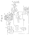
- FIG. 4 is a circuit diagram of a current supply circuit according to an embodiment of the present invention.
- reference number 31 denotes a microprocessor (MPU), 31 a digital-to-analog (D/A) convertor, 33 an operational amplifier, 34 a speed control filter, 35 a position control filter, 37 an operational amplifier, 38 a power amplifier, 39 a motor, 40 a differential amplifier, 41 a digital-to-analog (D/A) convertor, 42 an analog-to-digital convertor, 43 a buffer, and 44 a RAM.
- MPU microprocessor
- D/A digital-to-analog
- D/A digital-to-analog
- 33 an operational amplifier
- 34 a speed control filter
- 35 a position control filter
- 37 an operational amplifier
- 38 a power amplifier
- 39 a motor
- 40 a differential amplifier
- 41 a digital-to-analog (D/A) convertor
- 42 an analog-to-digital convertor
- the reel-drive motor 39 has a tachcounter for counting the rotation of the reel as shown in Fig. 9, and the radius of the tape on the reel is detected based on the values counted by the tachcounter. That is, as shown in Fig. 9, the rotation detector is provided for each motor shaft (not-shown) of the supply reel and the take-up reel.
- the rotation detector of the supply reel has N-pieces slits, and that of the take-up reel has only one slit. Accordingly, the number of the slit, i.e., the rotation speed of the reel can be counted by the tachcounter.
- R M /R F N F /N
- R M is the radius of the tape of the supply reel
- R F is the radius of the tape of the take-up reel
- N is the number of slits
- N F is the number of the pulse of the supply reel during one rotation of the take-up reel.
- the microprocessor 31 determines the current to be supplied to motor 39 based on a conversion table shown in Fig. 8, and outputs a digital command (see, following formula) to the D/A convertor 32.
- This digital command is obtained by the digital value selected from the digital values having 8 bits-256 steps in accordance with the above current as explained in detail below. In the case, one step in 256 steps corresponds to 50 mA of the supply current to the motor 39.
- the conversion table is stored in the RAM 44.
- the conversion table having a relationship between the radius R of the tape and the supply current I m to the motor is previously stored in the storage unit, because the inertial moment of the empty reel, the motor and the wound tape mainly depends on the radius of the tape so that the current to be supplied to the motor can be determined based on the following formula.
- I m I a + I T + I d
- I m I a + I T + I d
- I m the supply current to the motor
- I a is the current caused by the inertia
- I T is the current caused by the tape tension
- I d is the current caused by the friction.
- the formula (5) can be replaced as follows.
- I m (C1(R i 4 - C2)/R + J E /R + J M /R)A/K T + FR/K T + (T v + T c )/K T
- A an accereletion speed (cm/sec2)
- K T is a torque constant of the motor (kg cm/A)
- C1 is the value of ⁇ ⁇ w/2, i.e., inertia constant
- C2 is R i 4, i.e., inertia contant
- ⁇ is a tape density (g/cm3)
- w is the tape width (cm)
- J E is the inertia of the empty reel (g cm2)
- J M is the inertia of the motor (g cm2)
- F is the tape tension (g)
- R is the radius of the tape (cm)
- T V is the friction torque for the viscosity (kg cm
- one step in 256 steps corresponds to the supply current of 50 mA to the motor, the digital value (below, digital command) to the D/A convertor 32 is obtained as follows.
- digital command I m /0.05
- the digital command to the D/A convertor 32 can be obtained by the formula (7), and this digital value is input to the D/A convertor 32.
- the D/A convertor 32 converts the digital command (digital command value) into the analog command (MDAC), and this analog command is input to the speed control filter 34 and the position control filter 35 through the operational amplifier 33.
- the speed control filter 34 is a low-pass filter formed by two resistor R15, R16 and a condenser C1. This filter 34 is provided to cut-off the frequency over 200 Hz. That is, the speed control filter 34 is necessary to prevent vibration in the vicinity of 1 KHz caused by the twist resonance of the shaft between the reel and the motor during the tape transfer.
- the position control filter 35 is a differential filter formed by the resistor R17, R18 and the condenser C2.
- the resistor 18 is connected in series to the condenser C2, and these are connected in parallel to the resistor R17.
- the position control filter 35 outputs the differential value corresponding to the difference value between the target rotational speed and the actual rotation speed of the motor, and is provided for detecting the tape run/stop state.
- the output of these filters 34 and 35 are input to the switch 36.
- the connection of the switch 36 is controlled by the microprocessor 31. Accordingly, the output of the speed control filter 34 is supplied to the resistor R11 in the tape run state, and the output of the position control filter 35 is supplied to the resistor R11 in the tape stop state.
- the voltage of 10 mV is supplied to the resistor R11 (at the point D) from the speed control filter 34, and this voltage corresponds to one step of the digital command from the microprocessor 31.
- This voltage of 10 mV is supplied to the inverted terminal of the operational amplifier 37 through the resistor R11.
- the non-inverted terminal of the operational amplifier 37 is connected to the ground, and the output of the operational amplifier 37 is connected to the power amplifier 38 which functions as a constant current generating circuit.
- the output of the power amplifier 38 is supplied to the series circuit formed by the motor and the resistor R12.
- the current supplied to the motor 39 is detected by the voltage across the resistor R12 (A-B), and this voltage is supplied to the differential amplifier 40.
- the output of the differential amplifier 40 is supplied to the inverted terminal of the operational amplifier 37.
- the operational amplifier 37, the power amplifier 38, the motor 39 and the differential amplifier 40 are the same components 12 to 15 in Fig. 1. Accordingly, the detailed structure is omitted.
- the output voltage of differential amplifier 40 i.e., input voltage of resistor R13, see, point C
- the input voltage of the resistor R11 see, point D
- resistor R11, R12 and R13 there is dispersion value of elements, for example, resistor R11, R12 and R13 so that the voltage at point C does not always coincide with the voltage at the point D in the absolute value.
- the present invention solves this dispersion of the elements as follows.
- the voltage at the point C is converted into the digital value by the A/D convertor 42, and this digital value is input to the microprocessor 31 through the buffer 43.
- the microprocessor 31 previously prepares the correction table having the relationship between the digital value (i.e., the actual voltage at the point C) and the command value to the switch 36 (i.e., the corresponding voltage at the point D), and this correction table is stored in the RAM 44.
- the microprocessor 31 supplies the digital command value as a target value to the D/A convertor 32, and determines a correction command HDAC corresponding to the command value with reference to the correction table.
- the correction command HDAC corresponds to an error to be corrected as explained below.
- the D/A converter 41 converts the correction command HDAC into the analog value, and this analog value is supplied to the inverted terminal of the operational amplifier 37 through the resistor 14. Accordingly, it is possible to correct the voltage at the point C so as to become an equal voltage at the point D in the absolute value. Accordingly, it is possible to supply the current to the motor 39 in accordance with a command from the microprocessor 31 regardless of the dispersion of the value of the resistors R11, R12 and R13.
- the digital command value is previously determined from the relationship between the radius of the tape and the supply current, and stored in the conversion table. Further, the relationship between the digital command value and the actual value is previously stored in the correction table. Accordingly, the digital command value is generated from the microprocessor with reference to the conversion table, and the error between the digital command value and the actual value is corrected with reference to the correction table.
- Figure 5 is a flowchart preparing the correction table. This flowchart is performed when the power of the current supply circuit is turned ON, or when the self-diagnosis operation is performed under the control of the microprocessor 31.
- the motor is locked during the process preparing the correction table, i.e., the rotation of the motor is stopped.
- a brushless motor is used as the reel-drive motor, and this brushless motor has Hall-elements each provided for corresponding phase winding. Accordingly, the motor can be locked by stopping the switching operation for the input of the Hall-element.
- step S1 the loop-counting number N is set to "10" so that loop from the steps S2 to S7 is repeated 10 times.
- step S2 the digital command value from the microprocessor 31 is set to "N ⁇ ".
- the coefficient ⁇ is previously set to slightly smaller value than the value of 1/10 of the maximum command value.
- the actual current corresponding to the command value N ⁇ is supplied to the motor 39 through the filter, the switch, the operational amplifier, and the power amplifier. Accordingly, the voltage across the resistor R12 is detected and the feedback control is performed from the resistor R12 to the operational amplifier 40.
- step S3 after step S2, the wait time of about 3 m-sec is necessary for the next process, because a predetermined wait time is necessary for convergence of the supply current to the motor 39 in the feedback control operation.
- step 4 the voltage at point C is converted to the digital value by the A/D convertor 42, and this digital value ADC is input to the microprocessor 31.
- step 5 the microprocessor 31 stores the digital value into the RAM 44 as an actual value ADC (N).
- step 6 the microprocessor determines whether or not the counting number N-1 is "0", and when the counting number N-1 is not "0", the process moves to step 7, and when the counting number N-1 is "0", the process moves to step 8.
- step 7 the loop-counting number N is decreased, and the process is returned to the step S2 so that the steps S2 to S7 is repeated until the counting number N-1 becomes "0".
- Figure 6 is a graph explaining the error between the target value and the actual value
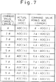
- Figure 7 shows a correction table according to the present invention.
- the ordinate denotes the actual value ADC(N) and the target value (i.e., digital command value)
- the abscissa denotes the digital command value
- the dotted line denotes the target value
- the solid line denotes the actual value.
- the error is provided by the difference between the target value and the actual value.
- each actual value ADC(N) is the value at each command value so that the each error (i.e., correction value) is determined by the difference between the command value and the actual value as shown in the table.
- the supply current to the motor is detected, and the voltage corresponding to the supply current is fed-back to the microprocessor to prepare the correction table.
- the supply current is controlled by the microprocessor based on the correction table.
- Figure 8 shows one example of a conversion table between the radius of a tape and the supply current to the motor.
- the relationship between the radius of the tape and the supply current is obtained form the formula (1) to (7), and this relationship is stored in the memory (RAM) 44 as the conversion table 1a (see, Fig. 2). That is, as is obvious from the conversion table, it is possible to easily obtain the relationship among the radius of the tape, the supply current and the digital command of the D/A convertor 32.
- the supply current I m to the motor is obtained from the formula (5) as explained above. Accordingly, the digital value to the D/A convertor 32 is obtained as "57" based on the formula (7).
- Figure 9 is a view explaining the rotation of the supply reel and the take-up reel.
- the rotation detector is provided for the supply reel and the take-up reel.
- the rotation detector of the supply reel has N-pieces slits, and the rotation detector of the take-up reel has only one slit. As is known, the rotation speed of each reel is detected by the number of the slit which the light is turned ON/OFF.
Abstract
Description
- The present invention relates to a current supply circuit and a control method for a supply current to a reel-drive motor in a magnetic apparatus.
- There is known a magnetic tape apparatus of a type that a magnetic tape is transferred from a supply reel to a take-up reel through a magnetic head, such that tape tension in the vicinity of the magnetic head is maintained at a constant value without a mechanical tape buffer which applies mechanical tension to the magnetic tape.
- In such a magnetic tape apparatus, in order to transfer the magnetic tape from the supply reel to the take-up reel at a constant tape tension and a constant tape speed, the reel-drive motor must be controlled under a torque corrected by various parameters, for example, a reference torque, a difference torque caused by a change in the radius of a magnetic tape wound on the reel (below, a radius of a tape), a friction torque caused by the reel, and an inertial moment caused by the rotation of the reel.
- A current supply circuit is provided for supplying the current to the reel-drive motor in accordance with a command that is generated in response to the radius of the tape and the actual tape speed so that it is possible to apply the corrected torque to the reel-drive motor.
- The object of the present invention is to provide a current supply circuit and a control method enabling a constant supply current to a reel drive motor in precisely response to a command from a command unit without a mechanical tension sensor and regardless of the dispersion of a value of electrical elements, particularly, resistor in the current supply circuit.
- In accordance with one aspect of the present invention, there is provided a current supply circuit for supplying a current to a reel-drive motor in a magnetic tape apparatus, including:
a conversion table storing a relationship between a radius of the magnetic tape wound on a reel and a target current to be supplied to the reel-drive motor, and the target current being converted to a digital command;
a correction table storing a relationship between the digital command and an actual current flowing in the motor when the digital command is applied to the motor, the actual current being converted to a digital value;
a command unit for outputting the digital command corresponding to the target current in accordance with the conversion table;
a supply current control unit for supplying an analog current corresponding to the digital command to the motor;
a first correction unit for applying a first correction signal to the supply current control unit in response to the actual current flowing in the motor; and
a second correction unit for supplying a second correction signal to the supply current control unit in accordance with an error to be corrected from the correction table with reference to the digital command. - In one preferred embodiment, the supply current control unit has an operational amplifier of which a non-inverted terminal (+) is connected to a ground and an inverted terminal (-) is connected to a first resistor and a second resistor, the first correction signal being input to the inverted terminal through the first resistor, and an output of the command unit being connected to the inverted terminal through the second resistor.
- In another preferred embodiment, the supply current control means further comprises two filters connected to the first resistor through a switch unit which switches between two filters, one filter being a low-pass filter for a speed control provided to cut-off over predetermined frequency, and the other filter being a differential filter for position control provided to detect the tape run/stop state.
- In another aspect of the present invention, there is provided a control method for a supply current to a reel-drive motor in a magnetic tape apparatus, the step including:
previously providing a conversion table storing a relationship between a radius of the magnetic tape wound on a reel and a target current to be supplied to the reel-drive motor, and the target current being converted to a digital command;
providing a correction table storing a relationship between the digital command and an actual current flowing the motor when the digital command is applied to the motor, the actual current being converted to a digital value;
outputting the digital command corresponding to the target current from a command unit in accordance with the conversion table;
supplying an analog current corresponding to the digital command from a supply current control unit to the motor;
applying a first correction signal from a first correction unit to the supply current control unit in response to the actual current flowing in the motor; and
supplying a second correction signal from a second correction unit to the supply current control unit in accordance with an error to be corrected from the correction table with reference to the digital command. - In the drawings:
- Fig. 1 shows a conventional current supply circuit in a magnetic tape apparatus;
- Fig. 2 is a basic block diagram of a current supply circuit in a magnetic tape apparatus according to the present invention;
- Fig. 3 is a schematic block diagram of a magnetic tape apparatus such that a magnetic tape is transferred from a supply reel to a take-up reel through a magnetic head without a mechanical tape buffer;
- Fig. 4 is a circuit diagram of a current supply circuit according to an embodiment of the present invention;
- Fig. 5 is a flowchart preparing a correction table;
- Fig. 6 is a graph explaining an error between a target value (i.e., command value) and an actual value;
- Fig. 7 shows a correction table according to the present invention;
- Fig. 8 shows one example of a conversion table between a radius of a tape and a supply current to a motor according to the present invention; and
- Fig. 9 is a view explaining the rotation of the supply reel and the take-up reel.
- Before describing the preferred embodiments, a conventional current supply circuit in a magnetic tape apparatus and its problems will be explained in detail below.
- Figure 1 shows a conventional current supply circuit in a magnetic tape apparatus. In Fig. 1, reference number 11 denotes a command circuit, 12 an operational amplifier, 13 a power amplifier, 14 a motor, 15 a differential amplifier, 16 a tension sensor, and 17 a filter. A command "a" indicating tape speed and a value "b" indicating the radius of the tape are input to the command circuit 11. The value "b" is detected by a tachometer (not shown) which is structurally coupled to the shaft of the reel-drive motor 14. Based on these values "a" and "b", the command circuit 11 supplies the voltage to the inverted terminal (-) of the
operational amplifier 12. This voltage corresponds to the current to be supplied to the reel-drive motor 14. The non-inverted terminal (+) of theoperational amplifier 12 is connected to the ground, and the output of theoperational amplifier 12 is connected to thepower amplifier 13 used as a constant current generating circuit. The output of thepower amplifier 13 is supplied to the motor 14, and the resistor R2 is connected between the motor 14 and the ground. - The amount of the current supplied to the motor 14 is detected by the voltage across the resistor R2, and the detected voltage is supplied to the
differential amplifier 15. The output of thedifferential amplifier 15 is supplied to the inverted terminal of theoperational amplifier 12 through the resistor R3. Further, the output of thetension sensor 16 is supplied to the inverted terminal of theoperational amplifier 12 through thefilter 17. - Assuming that, first, a current of 50 mA is supplied to the motor 14 for every output voltage of 10 mV from the command circuit 11, second, the feed-back resistor R2 is 0.1 Ω, third, the amplification degree of the
differential amplifier 15 is minus two times (-2 times), finally, the value of the resistor R1 is equal to that of the resistor R3, the voltage of the resistor R1 is equal to that of the resistor R3, the voltage of the resistor R1 is equal to that of the resistor R3 in an absolute value but opposite in sign so that "0" volt is always supplied to the inverted terminal of theoperational amplifier 12. - That is, since the voltage across the resistor R2 becomes 5 mV (50 mA x 0.1 Ω) so that the output of the
differential amplifier 15 becomes -10 mV, the inverted terminal of theoperational amplifier 12 becomes 0 V when the absolute value of the resistor R1 is equal to that of the resistor R3. - In this case, for example, when the current of 48 mA (note, it is not 50 mA) is supplied to the motor 14 when the output voltage of the command circuit 11 is 10 mV, the voltage across the resistor R2 becomes 4.8 mV so that the output voltage of the
differential amplifier 15 becomes -9.6 mV. - That is, since the input voltage of the resistor R1 is 10 mV (i.e., the output voltage of the command circuit 11) and the input voltage of the resistor R3 (i.e., the output voltage of the differential amplifier 15) is -9.6mV, the voltage of 0.4 mV is input to the inverted terminal of the
operational amplifier 12 when the absolute value of the resistor R1 is equal to that of the resistor R3. Accordingly, the increased current corresponding to the voltage of 0.4 mV is applied from thepower amplifier 13 to the motor 14 so that the increased voltage across the resistor R2 is fed-back to thedifferential amplifier 15 and the absolute value of the output voltage of the command circuit 11 is coincided with that of thedifferential amplifier 15. - As a result of the above feed-back control, since the absolute value of the output voltage of the command circuit 11 coincides with that of the
differential amplifier 15, the voltage of the inverted terminal of theoperational amplifier 12 again becomes the voltage 0 V so that the increment of the current from thepower amplifier 13 is stopped. As a result, the constant current precisely corresponding to the output of the command circuit 11 is supplied to the motor 14. - There are, however, problems in the above conventional circuit. That is, for resistors R1 to R3, there is large dispersion of value caused by the manufacturing process, and there is large fluctuation of value caused by change of the temperature. Accordingly, the current corresponding to the output of the command circuit is not precisely supplied to the motor so that it is very difficult to obtain precise control of the supply current to the motor in the conventional current supply circuit.
- As one countermeasure of the above problem, the resistors R1 to R3 each having small dispersion value are provided for obtaining precise control of the supply current. There is, however, a fluctuation of about 6% in the supply current as a minimum value even if high grade resistors are used. As a result, the drive torque of the motor fluctuates, and the tape tension also fluctuates.
- As another countermeasure of the above problem, the
mechanical tension sensor 16 is provided on the magnetic tape path for detecting the tape tension, and the output current from thepower amplifier 13 is corrected in accordance with a change in the tape tension. However, the structure of the mechanical tension sensor is relatively large so that it is not advantageous to miniaturize the magnetic tape apparatus. - Accordingly, the object of the present invention is to provide a,current supply circuit and a control method enabling a constant supply current to a reel-drive motor in precise response to the output of the command circuit without a tension sensor and regardless of the dispersion value of the resistors.
- Figure 2 is a basic structure of a current supply circuit according to the present invention. In Fig. 2, two reel-motors (M) 3 are provided to the supply reel and the take-up reel. The current supply circuit comprises a
command unit 1 for outputting a digital command based on a conversion table 1a which obtains a target current to be supplied to the reel-drive motor 3 from the radius of the tape, a supplycurrent control unit 2 for supplying the current to the reel-drive motor 3 in accordance with the command from thecommand unit 1, and afirst correction unit 4 for supplying a first correction signal to the supplycurrent control unit 2 in accordance with an actual current flowing in thereel drive motor 3. - Further, the current supply circuit comprises a
storage unit 5 for storing a correction table 5a formed by the voltage of a predetermined position in thefirst correction unit 4 and the correction value corresponding to the difference between the actual current and the target current, and asecond correction unit 6 for supplying a second correction signal to the supplycurrent control unit 2 in accordance with the correction value obtained from the correction table 5a based on the command of thecommand unit 1. - Further, in the above magnetic tape apparatus, a control method for supply current to the motor is as follows.
outputting a command corresponding to a target current to be supplied to thereel drive motor 3,
supplying the current from the supplycurrent control unit 2 to thereel drive motor 3 in accordance with the command,
supplying the first correction signal from thefirst correction unit 4 to the supplycurrent control unit 2 in accordance with the actual current flowing in thereel drive motor 3,
storing a correction table 5a formed by the voltage of a predetermined position in thefirst correction unit 4 and the correction value corresponding to the difference between the actual current and the target current, and
supplying a second correction signal to the supplycurrent control unit 2 in accordance with the correction value obtained from the correction table 5a based on the command of thecommand unit 1. - In the present invention, the conversion table is previously prepared based on the relationship between the radius of the tape and the supply current to the motor. Further, the correction table is also previously prepared based on the voltage of a predetermined position in the
first correction unit 4 and the correction value corresponding to the difference between the actual current and the target current. The correction value obtained from the correction table 5a is based on the command of thecommand unit 1, and the second correction signal is supplied to the supplycurrent control unit 2 in accordance with the above correction value. - Figure 3 is a schematic block diagram of a magnetic tape apparatus such that a magnetic tape is transferred from the supply reel to the take-up reel through a magnetic head without a mechanical tape buffer. In the drawing,
reference number 21 denotes a magnetic tape, 22 denotes a supply reel, 23 denotes a take-up reel, and 24 denotes a head guide having amagnetic head 241 and roller guides 242 and 243. Thereel drive motor 3 is independently provided to thesupply motor 22 and the take-upmotor 23. Themagnetic tape 21 is transferred from thesupply reel 21 to the take-up reel 23 through thehead guide 24. Further, "R" is the radius of the tape wound on the take-up reel 23. - Further, a magnetic
tape drive unit 25 and a magnetic tapedrive control unit 26 are provided as drive and control units. The current supply circuit according to the present invention is included in the magnetic tapedrive control unit 26. - As is obvious from the drawing, there are no tape buffer and mechanical tape tension sensor for adjusting the tape tension in the present invention. In the present invention, the tape tension in the vicinity of the
magnetic head 241 is maintained at a constant value without the tape buffer, and controlled by the torque of the reel-drive motor 3 so as to maintain a constant tape tension and a constant tape speed. - Figure 4 is a circuit diagram of a current supply circuit according to an embodiment of the present invention. In the drawing,
reference number 31 denotes a microprocessor (MPU), 31 a digital-to-analog (D/A) convertor, 33 an operational amplifier, 34 a speed control filter, 35 a position control filter, 37 an operational amplifier, 38 a power amplifier, 39 a motor, 40 a differential amplifier, 41 a digital-to-analog (D/A) convertor, 42 an analog-to-digital convertor, 43 a buffer, and 44 a RAM. - The reel-
drive motor 39 has a tachcounter for counting the rotation of the reel as shown in Fig. 9, and the radius of the tape on the reel is detected based on the values counted by the tachcounter. That is, as shown in Fig. 9, the rotation detector is provided for each motor shaft (not-shown) of the supply reel and the take-up reel. The rotation detector of the supply reel has N-pieces slits, and that of the take-up reel has only one slit. Accordingly, the number of the slit, i.e., the rotation speed of the reel can be counted by the tachcounter. - How to obtain the radius of the tape is explained below. That is, the relationship between the radius of the tape and the number of the slit is expressed as follows.

Where,
RM is the radius of the tape of the supply reel,
RF is the radius of the tape of the take-up reel,
N is the number of slits, and
NF is the number of the pulse of the supply reel during one rotation of the take-up reel. - Accordingly, the following formula is obtained based on the above formula (1).

Where,
Ri is the radius of the hab (i.e., emplty reel),
R₀ is the radius of the fully wound tape, and
w is the tape width. - The formula (2) can be replaced as follows.


Where, C is
- Accordingly, it is possible to obtain the radius of the tape based on the formula (3) and (4).
- When the radius of the tape is input to the
microprocessor 31, the microprocessor 31 (for example, 8 bits processor) determines the current to be supplied tomotor 39 based on a conversion table shown in Fig. 8, and outputs a digital command (see, following formula) to the D/A convertor 32. This digital command is obtained by the digital value selected from the digital values having 8 bits-256 steps in accordance with the above current as explained in detail below. In the case, one step in 256 steps corresponds to 50 mA of the supply current to themotor 39. The conversion table is stored in theRAM 44. - As shown in Fig. 8, the conversion table having a relationship between the radius R of the tape and the supply current Im to the motor is previously stored in the storage unit, because the inertial moment of the empty reel, the motor and the wound tape mainly depends on the radius of the tape so that the current to be supplied to the motor can be determined based on the following formula.

Where,
Im is the supply current to the motor,
Ia is the current caused by the inertia,
IT is the current caused by the tape tension, and
Id is the current caused by the friction. - The formula (5) can be replaced as follows.

Where,
A is an accereletion speed (cm/sec²),
KT is a torque constant of the motor (kg cm/A),
C₁ is the value of π ρ w/2, i.e., inertia constant,
C₂ isR i⁴, i.e., inertia contant,
ρ is a tape density (g/cm³),
w is the tape width (cm),
JE is the inertia of the empty reel (g cm²),
JM is the inertia of the motor (g cm²),
F is the tape tension (g),
R is the radius of the tape (cm),
TV is the friction torque for the viscosity (kg cm),
and,
Tc is the friction torque for the viscosity (kg cm). - As explained above, one step in 256 steps corresponds to the supply current of 50 mA to the motor, the digital value (below, digital command) to the D/
A convertor 32 is obtained as follows.
- Accordingly, when the supply current to the motor is determined from the radius of the tape based on the conversion table shown in Fig. 8, the digital command to the D/
A convertor 32 can be obtained by the formula (7), and this digital value is input to the D/A convertor 32. - Further, the D/
A convertor 32 converts the digital command (digital command value) into the analog command (MDAC), and this analog command is input to thespeed control filter 34 and theposition control filter 35 through theoperational amplifier 33. Thespeed control filter 34 is a low-pass filter formed by two resistor R15, R16 and a condenser C1. Thisfilter 34 is provided to cut-off the frequency over 200 Hz. That is, thespeed control filter 34 is necessary to prevent vibration in the vicinity of 1 KHz caused by the twist resonance of the shaft between the reel and the motor during the tape transfer. - The
position control filter 35 is a differential filter formed by the resistor R17, R18 and the condenser C2. The resistor 18 is connected in series to the condenser C2, and these are connected in parallel to the resistor R17. Theposition control filter 35 outputs the differential value corresponding to the difference value between the target rotational speed and the actual rotation speed of the motor, and is provided for detecting the tape run/stop state. - The output of these
filters switch 36. The connection of theswitch 36 is controlled by themicroprocessor 31. Accordingly, the output of thespeed control filter 34 is supplied to the resistor R11 in the tape run state, and the output of theposition control filter 35 is supplied to the resistor R11 in the tape stop state. - In the tape run state, the voltage of 10 mV is supplied to the resistor R11 (at the point D) from the
speed control filter 34, and this voltage corresponds to one step of the digital command from themicroprocessor 31. This voltage of 10 mV is supplied to the inverted terminal of theoperational amplifier 37 through the resistor R11. The non-inverted terminal of theoperational amplifier 37 is connected to the ground, and the output of theoperational amplifier 37 is connected to thepower amplifier 38 which functions as a constant current generating circuit. The output of thepower amplifier 38 is supplied to the series circuit formed by the motor and the resistor R12. The current supplied to themotor 39 is detected by the voltage across the resistor R12 (A-B), and this voltage is supplied to thedifferential amplifier 40. The output of thedifferential amplifier 40 is supplied to the inverted terminal of theoperational amplifier 37. - As is obvious from a comparison with Fig. 1, the
operational amplifier 37, thepower amplifier 38, themotor 39 and thedifferential amplifier 40 are thesame components 12 to 15 in Fig. 1. Accordingly, the detailed structure is omitted. - As explained above, when, first, the value of the resistor R11 is equal to the value of the resistor R13, second, the value of the resistor R12 is 0.1Ω, and third, the amplification rate of the
differential amplifier 40 is minus two times, the output voltage of differential amplifier 40 (i.e., input voltage of resistor R13, see, point C) is equal to the input voltage of the resistor R11 (see, point D) in the absolute value but opposite in sign. - As explained in Fig. 1, however, there is dispersion value of elements, for example, resistor R11, R12 and R13 so that the voltage at point C does not always coincide with the voltage at the point D in the absolute value.
- Accordingly, the present invention solves this dispersion of the elements as follows. The voltage at the point C is converted into the digital value by the A/
D convertor 42, and this digital value is input to themicroprocessor 31 through thebuffer 43. Themicroprocessor 31 previously prepares the correction table having the relationship between the digital value (i.e., the actual voltage at the point C) and the command value to the switch 36 (i.e., the corresponding voltage at the point D), and this correction table is stored in theRAM 44. - After above step, the
microprocessor 31 supplies the digital command value as a target value to the D/A convertor 32, and determines a correction command HDAC corresponding to the command value with reference to the correction table. The correction command HDAC corresponds to an error to be corrected as explained below. - Further, the D/
A converter 41 converts the correction command HDAC into the analog value, and this analog value is supplied to the inverted terminal of theoperational amplifier 37 through the resistor 14. Accordingly, it is possible to correct the voltage at the point C so as to become an equal voltage at the point D in the absolute value. Accordingly, it is possible to supply the current to themotor 39 in accordance with a command from themicroprocessor 31 regardless of the dispersion of the value of the resistors R11, R12 and R13. - Briefly, as explained above, the digital command value is previously determined from the relationship between the radius of the tape and the supply current, and stored in the conversion table. Further, the relationship between the digital command value and the actual value is previously stored in the correction table. Accordingly, the digital command value is generated from the microprocessor with reference to the conversion table, and the error between the digital command value and the actual value is corrected with reference to the correction table.
- Figure 5 is a flowchart preparing the correction table. This flowchart is performed when the power of the current supply circuit is turned ON, or when the self-diagnosis operation is performed under the control of the
microprocessor 31. - The motor is locked during the process preparing the correction table, i.e., the rotation of the motor is stopped. In general, a brushless motor is used as the reel-drive motor, and this brushless motor has Hall-elements each provided for corresponding phase winding. Accordingly, the motor can be locked by stopping the switching operation for the input of the Hall-element.
- The steps for preparing the correction table are explained in detail below.
- In step S1, the loop-counting number N is set to "10" so that loop from the steps S2 to S7 is repeated 10 times.
- In step S2, the digital command value from the
microprocessor 31 is set to "Nα". In this case, the coefficient α is previously set to slightly smaller value than the value of 1/10 of the maximum command value. The actual current corresponding to the command value Nα is supplied to themotor 39 through the filter, the switch, the operational amplifier, and the power amplifier. Accordingly, the voltage across the resistor R12 is detected and the feedback control is performed from the resistor R12 to theoperational amplifier 40. - In step S3, after step S2, the wait time of about 3 m-sec is necessary for the next process, because a predetermined wait time is necessary for convergence of the supply current to the
motor 39 in the feedback control operation. - In
step 4, the voltage at point C is converted to the digital value by the A/D convertor 42, and this digital value ADC is input to themicroprocessor 31. - In
step 5, themicroprocessor 31 stores the digital value into theRAM 44 as an actual value ADC (N). - In
step 6, the microprocessor determines whether or not the counting number N-1 is "0", and when the counting number N-1 is not "0", the process moves to step 7, and when the counting number N-1 is "0", the process moves to step 8. - In
step 7, the loop-counting number N is decreased, and the process is returned to the step S2 so that the steps S2 to S7 is repeated until the counting number N-1 becomes "0". - In
step 8, themicroprocessor 31 calculates each error in accordance with the actual value ADC (N) stored in theRAM 44 and the digital command value Nα (N = from 10 to 1) corresponding to the actual value ADC (N). - In
step 9, themicroprocessor 31 stores each error corresponding to the counting number N (= from 10 to 1) into theRAM 44 as the correction table. - Figure 6 is a graph explaining the error between the target value and the actual value, and Figure 7 shows a correction table according to the present invention. In Fig. 6, the ordinate denotes the actual value ADC(N) and the target value (i.e., digital command value), and the abscissa denotes the digital command value. Further, the dotted line denotes the target value, and the solid line denotes the actual value. As is obvious, the error is provided by the difference between the target value and the actual value.
- In Fig. 7, each actual value ADC(N) is the value at each command value so that the each error (i.e., correction value) is determined by the difference between the command value and the actual value as shown in the table.
- As explained above, the supply current to the motor is detected, and the voltage corresponding to the supply current is fed-back to the microprocessor to prepare the correction table. The supply current is controlled by the microprocessor based on the correction table.
- Figure 8 shows one example of a conversion table between the radius of a tape and the supply current to the motor. As explained above, the relationship between the radius of the tape and the supply current is obtained form the formula (1) to (7), and this relationship is stored in the memory (RAM) 44 as the conversion table 1a (see, Fig. 2). That is, as is obvious from the conversion table, it is possible to easily obtain the relationship among the radius of the tape, the supply current and the digital command of the D/
A convertor 32. - For example, when the radius R of the tape is 2.5 cm, the supply current Im to the motor is obtained from the formula (5) as explained above. Accordingly, the digital value to the D/
A convertor 32 is obtained as "57" based on the formula (7). - Figure 9 is a view explaining the rotation of the supply reel and the take-up reel. The rotation detector is provided for the supply reel and the take-up reel. The rotation detector of the supply reel has N-pieces slits, and the rotation detector of the take-up reel has only one slit. As is known, the rotation speed of each reel is detected by the number of the slit which the light is turned ON/OFF.
Claims (5)
- A current supply circuit for supplying a current to a reel-drive motor in a magnetic tape apparatus, comprising:
a conversion table (1a) storing a relationship between a radius of the magnetic tape wound on a reel and a target current to be supplied to the reel-drive motor (3), and the target current being converted to a digital command;
a correction table (5a) storing a relationship between the digital command and an actual current flowing in the motor when the digital command is applied to the motor, the actual current being converted to a digital value;
a command means (1) for outputting the digital command corresponding to the target current in accordance with the conversion table;
a supply current control means (2) for supplying an analog current corresponding to the digital command to the motor;
a first correction means (4) for applying a first correction signal to the supply current control means (2) in response to the actual current flowing in the motor; and
a second correction means (6) for supplying a second correction signal to the supply current control means (2) in accordance with an error to be corrected from the correction table (5a) with reference to the digital command. - A current supply circuit as claimed in claim 1, wherein said supply current control means comprises an operational amplifier (37) of which a non-inverted terminal (+) is connected to a ground (GND) and an inverted terminal (-) is connected to a first resistor (R11) and a second resistor (R13), the first correction signal being input to the inverted terminal through the first resistor, and an output of the command means being connected to the inverted terminal though the second resistor.
- A current supply circuit as claimed in claim 1 or 2, wherein said supply current control means further comprising two filter means (34, 35) connected to the first resistor through a switch means (36) that switches between two filters, one filter (34) being a low-pass filter for a speed control provided to cut-off a predetermined frequency, and the other filter (35) being a differential filter for position control provided to detect the tape run/stop state.
- A magnetic tape apparatus comprising:
two reel-drive motors for a supply and take-up reels;
a head guide having a magnetic head and two roller guides for transferring the magnetic tape from the supply reel to the take-up reel, and no having a mechanical tension sensor to provide a tape tension for the magnetic tape;
a magnetic tape drive unit for driving the reel-drive motors; and
a magnetic tape drive control unit comprising a current supply unit for controlling a supply current to the magnetic tape drive unit to control the tape tension through a torque of each reel-drive motor. - A control method for a supply current to a reel-drive motor in a magnetic tape apparatus, the step comprising:
previously providing a conversion table (1a) storing a relationship between a radius of the magnetic tape wound on a reel and a target current to be supplied to the reel-drive motor (3), and the target current being converted to a digital command;
providing a correction table (5a) storing a relationship between the digital command and an actual current flowing in the motor when the digital command is applied to the motor, the actual current being converted to a digital value;
outputting the digital command corresponding to the target current from a command means (1) in accordance with the conversion table;
supplying an analog current corresponding to the digital command from a supply current control means (2) to the motor;
applying a first correction signal from a first correction means (4) to the supply current control means (2) in response to the actual current flowing in the motor; and
supplying a second correction signal from a second correction means (6) to the supply current control means (2) in accordance with an error to be corrected from the correction table (5a) with reference to the digital command.
Applications Claiming Priority (2)
| Application Number | Priority Date | Filing Date | Title |
|---|---|---|---|
| JP3202910A JP2615518B2 (en) | 1991-08-13 | 1991-08-13 | Current supply circuit and current supply control method for magnetic tape device |
| JP202910/91 | 1991-08-13 |
Publications (2)
| Publication Number | Publication Date |
|---|---|
| EP0527643A2 true EP0527643A2 (en) | 1993-02-17 |
| EP0527643A3 EP0527643A3 (en) | 1994-03-02 |
Family
ID=16465203
Family Applications (1)
| Application Number | Title | Priority Date | Filing Date |
|---|---|---|---|
| EP92307384A Withdrawn EP0527643A2 (en) | 1991-08-13 | 1992-08-12 | A current supply circuit and control method for supply currrent in a magnetic tape apparatus |
Country Status (3)
| Country | Link |
|---|---|
| US (1) | US5465918A (en) |
| EP (1) | EP0527643A2 (en) |
| JP (1) | JP2615518B2 (en) |
Cited By (2)
| Publication number | Priority date | Publication date | Assignee | Title |
|---|---|---|---|---|
| WO1996010252A1 (en) * | 1994-09-26 | 1996-04-04 | Philips Electronics N.V. | Recording and/or reproducing apparatus including a servo control loop |
| EP1651145B1 (en) | 2003-07-28 | 2016-11-16 | Abbott Medical Optics Inc. | Primary and supplemental intraocular lens system |
Families Citing this family (6)
| Publication number | Priority date | Publication date | Assignee | Title |
|---|---|---|---|---|
| KR100279697B1 (en) * | 1992-11-09 | 2001-02-01 | 이데이 노부유끼 | Tape Tension Control |
| US5712539A (en) * | 1995-06-07 | 1998-01-27 | Exabyte Corporation | Digital acoustic noise reduction in electric motors driven by switching power amplifiers |
| JP2000215559A (en) * | 1999-01-25 | 2000-08-04 | Matsushita Electric Ind Co Ltd | Running device of tape-like medium |
| US6760176B2 (en) | 2001-04-17 | 2004-07-06 | International Business Machines Corporation | Method and apparatus for calibrating a tape transport servo system |
| KR20160015075A (en) * | 2014-07-30 | 2016-02-12 | 삼성전기주식회사 | Multi output power supplying apparatus, and output circuit thereof |
| US10347282B2 (en) * | 2017-06-23 | 2019-07-09 | International Business Machines Corporation | Tape transport control with suppression of time-varying tension disturbances |
Citations (8)
| Publication number | Priority date | Publication date | Assignee | Title |
|---|---|---|---|---|
| US4398227A (en) * | 1981-03-16 | 1983-08-09 | Storage Technology Corporation | Magnetic tape drive with adaptive servo |
| JPS58158068A (en) * | 1982-03-15 | 1983-09-20 | Matsushita Electric Ind Co Ltd | Tape take-up device |
| EP0186591A2 (en) * | 1984-12-21 | 1986-07-02 | Fujitsu Limited | Motor control apparatus for reel-to-reel tape drive system |
| US4628375A (en) * | 1985-06-28 | 1986-12-09 | Transamerica Delaval Inc. | Control systems for magnetic recording tapes |
| JPS62150546A (en) * | 1985-12-25 | 1987-07-04 | Hitachi Ltd | Control circuit for reel motor |
| DE3818360A1 (en) * | 1987-05-29 | 1988-12-08 | Hitachi Ltd | METHOD AND DEVICE FOR CONTROLLING A TAPE TRANSPORT FROM REEL TO REEL |
| JPH0294153A (en) * | 1988-09-30 | 1990-04-04 | Mitsumi Electric Co Ltd | Magnetic tape recording/reproducing device |
| US5012989A (en) * | 1989-11-24 | 1991-05-07 | Eastman Kodak Company | Apparatus and method for tape velocity and tension control in a capstanless magnetic tape transport |
Family Cites Families (13)
| Publication number | Priority date | Publication date | Assignee | Title |
|---|---|---|---|---|
| US4015799A (en) * | 1975-11-14 | 1977-04-05 | International Business Machines Corporation | Adaptive reel-to-reel tape control system |
| US4125881A (en) * | 1977-05-19 | 1978-11-14 | International Business Machines Corporation | Tape motion control for reel-to-reel drive |
| US4256996A (en) * | 1979-01-29 | 1981-03-17 | Spin Physics, Inc. | Web transport system |
| US4531166A (en) * | 1981-03-16 | 1985-07-23 | Storage Technology Corporation | Magnetic tape drive with adaptive servo |
| JPS5898866A (en) * | 1981-12-09 | 1983-06-11 | Hitachi Ltd | Controller for transportation of magnetic tape |
| JPS615462A (en) * | 1984-05-31 | 1986-01-11 | Fujitsu Ltd | Stop lock system |
| US4993660A (en) * | 1985-05-31 | 1991-02-19 | Canon Kabushiki Kaisha | Reel drive device |
| US4777413A (en) * | 1986-09-19 | 1988-10-11 | Pioneer Electronic Corporation | Tape speed control device |
| JPH0728598Y2 (en) * | 1986-09-25 | 1995-06-28 | ナカミチ株式会社 | Tape feed control device |
| US4977466A (en) * | 1988-07-04 | 1990-12-11 | Fuji Photo Film Co., Ltd. | Magnetic tape wind-up control method, and tape wind-up apparatus |
| JP2815155B2 (en) * | 1988-09-20 | 1998-10-27 | 株式会社日立製作所 | Control device for tape transfer device |
| JP2930593B2 (en) * | 1988-09-20 | 1999-08-03 | 株式会社日立製作所 | Control device for tape transfer device |
| US5222684A (en) * | 1990-03-19 | 1993-06-29 | Matsushita Electric Industrial Co., Ltd. | Tape driving apparatus for tape medium record reproducing apparatus |
-
1991
- 1991-08-13 JP JP3202910A patent/JP2615518B2/en not_active Expired - Fee Related
-
1992
- 1992-08-12 EP EP92307384A patent/EP0527643A2/en not_active Withdrawn
-
1994
- 1994-10-04 US US08/317,845 patent/US5465918A/en not_active Expired - Fee Related
Patent Citations (8)
| Publication number | Priority date | Publication date | Assignee | Title |
|---|---|---|---|---|
| US4398227A (en) * | 1981-03-16 | 1983-08-09 | Storage Technology Corporation | Magnetic tape drive with adaptive servo |
| JPS58158068A (en) * | 1982-03-15 | 1983-09-20 | Matsushita Electric Ind Co Ltd | Tape take-up device |
| EP0186591A2 (en) * | 1984-12-21 | 1986-07-02 | Fujitsu Limited | Motor control apparatus for reel-to-reel tape drive system |
| US4628375A (en) * | 1985-06-28 | 1986-12-09 | Transamerica Delaval Inc. | Control systems for magnetic recording tapes |
| JPS62150546A (en) * | 1985-12-25 | 1987-07-04 | Hitachi Ltd | Control circuit for reel motor |
| DE3818360A1 (en) * | 1987-05-29 | 1988-12-08 | Hitachi Ltd | METHOD AND DEVICE FOR CONTROLLING A TAPE TRANSPORT FROM REEL TO REEL |
| JPH0294153A (en) * | 1988-09-30 | 1990-04-04 | Mitsumi Electric Co Ltd | Magnetic tape recording/reproducing device |
| US5012989A (en) * | 1989-11-24 | 1991-05-07 | Eastman Kodak Company | Apparatus and method for tape velocity and tension control in a capstanless magnetic tape transport |
Non-Patent Citations (3)
| Title |
|---|
| PATENT ABSTRACTS OF JAPAN vol. 11, no. 383 (P-646)15 December 1987 & JP-A-62 150 546 (HITACHI LTD.) 4 July 1987 * |
| PATENT ABSTRACTS OF JAPAN vol. 14, no. 301 (P-1069)28 June 1990 & JP-A-02 094 153 (MITSUMI ELECTRIC CO LTD) 4 April 1990 * |
| PATENT ABSTRACTS OF JAPAN vol. 7, no. 282 (P-243)16 December 1983 & JP-A-58 158 068 (MATSUSHITA DENKI SANGYO K.K.) 20 September 1983 * |
Cited By (2)
| Publication number | Priority date | Publication date | Assignee | Title |
|---|---|---|---|---|
| WO1996010252A1 (en) * | 1994-09-26 | 1996-04-04 | Philips Electronics N.V. | Recording and/or reproducing apparatus including a servo control loop |
| EP1651145B1 (en) | 2003-07-28 | 2016-11-16 | Abbott Medical Optics Inc. | Primary and supplemental intraocular lens system |
Also Published As
| Publication number | Publication date |
|---|---|
| JPH0547077A (en) | 1993-02-26 |
| JP2615518B2 (en) | 1997-05-28 |
| EP0527643A3 (en) | 1994-03-02 |
| US5465918A (en) | 1995-11-14 |
Similar Documents
| Publication | Publication Date | Title |
|---|---|---|
| US5039027A (en) | Method for control of tape tension between the reels and apparatus therefor | |
| US4448368A (en) | Control for tape drive system | |
| US4851755A (en) | Low power stepper motor drive system and method | |
| US5259563A (en) | Magnetic recording/reproducing apparatus without capstan | |
| EP0164256B1 (en) | Motor control apparatus for reel-to-reel tape drive system | |
| US3733529A (en) | Plural motor tape drive speed control | |
| EP0527643A2 (en) | A current supply circuit and control method for supply currrent in a magnetic tape apparatus | |
| US3860187A (en) | Circuit for controlling the thread velocity in winding equipment with a traversing mechanism | |
| US5325028A (en) | System and method for magnetic tape leader block extraction | |
| EP0532238B1 (en) | Tape speed control apparatus | |
| US4743811A (en) | Adaptive control system for reel to reel web transport apparatus | |
| US5860610A (en) | Magnetic tape tension control device | |
| KR970002261B1 (en) | Speed control method and circuit of a rotor | |
| EP0938086B1 (en) | Optimized winding drive | |
| SU1720095A1 (en) | Magnetic tape linear speed stabilizer | |
| JP2663428B2 (en) | Tape diameter calculation device | |
| JP3044895B2 (en) | Magnetic recording / reproducing device | |
| JPH0757112B2 (en) | Speed control motor drive | |
| JPH02301053A (en) | Tape driving device | |
| JPH05307801A (en) | Device for taking up long size material | |
| JP3541581B2 (en) | Tape-shaped medium traveling device | |
| SU1461738A1 (en) | Apparatus for controlling the winding of continuous material | |
| JPH04155645A (en) | Tension controller | |
| JPS5930941A (en) | Control of multicolor free selecting motor | |
| JPH04195949A (en) | Motor controller |
Legal Events
| Date | Code | Title | Description |
|---|---|---|---|
| PUAI | Public reference made under article 153(3) epc to a published international application that has entered the european phase |
Free format text: ORIGINAL CODE: 0009012 |
|
| AK | Designated contracting states |
Kind code of ref document: A2 Designated state(s): DE FR GB |
|
| PUAL | Search report despatched |
Free format text: ORIGINAL CODE: 0009013 |
|
| AK | Designated contracting states |
Kind code of ref document: A3 Designated state(s): DE FR GB |
|
| 17P | Request for examination filed |
Effective date: 19940825 |
|
| 17Q | First examination report despatched |
Effective date: 19951122 |
|
| GRAG | Despatch of communication of intention to grant |
Free format text: ORIGINAL CODE: EPIDOS AGRA |
|
| GRAG | Despatch of communication of intention to grant |
Free format text: ORIGINAL CODE: EPIDOS AGRA |
|
| GRAH | Despatch of communication of intention to grant a patent |
Free format text: ORIGINAL CODE: EPIDOS IGRA |
|
| STAA | Information on the status of an ep patent application or granted ep patent |
Free format text: STATUS: THE APPLICATION HAS BEEN WITHDRAWN |
|
| GRAH | Despatch of communication of intention to grant a patent |
Free format text: ORIGINAL CODE: EPIDOS IGRA |
|
| 18W | Application withdrawn |
Withdrawal date: 19980626 |