EP0527518B1 - Self-adjusting, push to-release parking brake - Google Patents
Self-adjusting, push to-release parking brake Download PDFInfo
- Publication number
- EP0527518B1 EP0527518B1 EP92202246A EP92202246A EP0527518B1 EP 0527518 B1 EP0527518 B1 EP 0527518B1 EP 92202246 A EP92202246 A EP 92202246A EP 92202246 A EP92202246 A EP 92202246A EP 0527518 B1 EP0527518 B1 EP 0527518B1
- Authority
- EP
- European Patent Office
- Prior art keywords
- sector
- brake
- lever
- pawl
- applied position
- Prior art date
- Legal status (The legal status is an assumption and is not a legal conclusion. Google has not performed a legal analysis and makes no representation as to the accuracy of the status listed.)
- Expired - Lifetime
Links
Images


Classifications
-
- B—PERFORMING OPERATIONS; TRANSPORTING
- B60—VEHICLES IN GENERAL
- B60T—VEHICLE BRAKE CONTROL SYSTEMS OR PARTS THEREOF; BRAKE CONTROL SYSTEMS OR PARTS THEREOF, IN GENERAL; ARRANGEMENT OF BRAKING ELEMENTS ON VEHICLES IN GENERAL; PORTABLE DEVICES FOR PREVENTING UNWANTED MOVEMENT OF VEHICLES; VEHICLE MODIFICATIONS TO FACILITATE COOLING OF BRAKES
- B60T7/00—Brake-action initiating means
- B60T7/02—Brake-action initiating means for personal initiation
- B60T7/04—Brake-action initiating means for personal initiation foot actuated
- B60T7/045—Brake-action initiating means for personal initiation foot actuated with locking and release means, e.g. providing parking brake application
-
- Y—GENERAL TAGGING OF NEW TECHNOLOGICAL DEVELOPMENTS; GENERAL TAGGING OF CROSS-SECTIONAL TECHNOLOGIES SPANNING OVER SEVERAL SECTIONS OF THE IPC; TECHNICAL SUBJECTS COVERED BY FORMER USPC CROSS-REFERENCE ART COLLECTIONS [XRACs] AND DIGESTS
- Y10—TECHNICAL SUBJECTS COVERED BY FORMER USPC
- Y10T—TECHNICAL SUBJECTS COVERED BY FORMER US CLASSIFICATION
- Y10T74/00—Machine element or mechanism
- Y10T74/20—Control lever and linkage systems
- Y10T74/20576—Elements
- Y10T74/20636—Detents
- Y10T74/20672—Lever engaging rack
- Y10T74/20684—Lever carried pawl
Definitions
- This invention relates generally to apparatus for applying and releasing a vehicular parking brake.
- such apparatus includes a control with a foot-operated lever or pedal which, when depressed, acts to turn a toothed sector and apply tension to a cable in order to set the parking brake of the vehicle.
- a pawl engages and holds the sector to prevent the return springs of the brake and the brake clamp load from effecting release of the brake.
- a self-adjusting control includes an initially tightly wound torsion spring which urges the sector in a brake-applying direction.
- the sector is locked against being turned by the spring.
- the sector is unlocked and is automatically rotated by the tightly wound spring until the slack in the cable is taken up and the cable is tensioned sufficiently to preload the return of springs of the parking brake.
- the cable and the return springs are placed under a specified preload by the torsion spring once the cable has been hooked up and the sector has been released to the action of the torsion spring.
- Document US-A-5 001 942 discloses an apparatus (FIG . 1) for applying and releasing a vehicular parking brake as disclosed in the preamble of claim 1.
- This known apparatus is a hand operated brake which requires actuation of a release button.
- a push-to-release parking brake control is one which effects release of the parking brake when the foot-operated pedal is again depressed after the brake has been set. Depression of the pedal releases the pawl from the sector and allows release of the brake.
- the general aim of the present invention is to provide a new and improved self-adjusting, push-to-release brake control that is lighter in weight and lower in cost than prior controls of the same general type.
- the invention provides an apparatus for applying and releasing a vehicular parking brake in accordance with claim 1.
- the self-adjusting, push-to-release parking brake control according to the present invention produces a mechanical advantage of variable ratio to reduce the manual effort required to fully set the brake.
- a parking brake control in which the sector which holds the parking brake set is free to rotate relative to the pedal and effect self-adjustment once the control has been installed and the sector has been released to the action of the torsion spring.
- a control in which the pawl is uniquely controlled to effect push-to-release, and a control in which the cam for applying force to the cable is carried by the pedal and is of variable ratio.
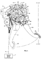
- the invention has been shown in the drawings as incorporated in control apparatus 10 for setting and releasing the parking brake of an automobile or other vehicle.
- the parking brake itself has been shown schematically by the box 11 in FIG. 1 and includes rear braking elements which are forced into engagement with drums or rotors when force is applied to the braking elements via a flexible cable 13 which is connected to the control 10.
- Return springs are associated with the braking elements and release the latter when the tensile force applied to the cable by the control is relieved.
- the parking brake control 10 includes a main supporting bracket 15 which is adapted to be attached by fasteners 16 (FIG. 2) to a fixed frame member 17 beneath the instrument panel of the vehicle.
- a cover 18 is attached to and spaced laterally from the bracket and coacts with the latter to define a housing for several components of the control.
- an actuating lever 20 which herein is in the form of a foot-operated pedal having an elongated arm 21 with a rubber pad 22 on the lower end thereof.
- a rivet 23 (FIG.3) extends through the bracket 15, a generally circular mounting plate 24 of the pedal 20, and the cover 18 and supports the pedal to turn about a laterally extending horizontal axis.
- a contractile spring 25 Connected between the bracket and the plate 24 of the pedal is a contractile spring 25 which urges the pedal to turn counterclockwise about the rivet 23 and to a brake-released position shown in solid lines of Fig.1.
- the pedal is in its released position, the upper side of the arm 21 engages and is stopped by a rubber bumper 26 on the cover 18.
- Clockwise turning of the pedal 20 to a brake-applied position shown in phantom lines in FIG. 1 effects clockwise turning of a toothed sector 30 which pulls on the cable 13 to apply the brake 11.
- the sector 30 is supported to turn about the rivet 23 and is in the form of a flat plate having an edge concentric with the rivet and formed with angularly spaced ratched teeth 31 (FIGS. 5 and 6).
- a rod-like connector 32 on the end of the cable 13 fits within a forked bracket 34 (FIG.5) which is secured rigidly to and projects from one side of the sector, the cable thus being fastened to the sector.
- Drive means connect the pedal 20 to the sector 30 and effect clockwise turning of the sector to a brake-applied position when the pedal is depressed clockwise to its brake-applied position.
- the drive means includes a toothed pawl 35 (FIG.6) which is supported to turn about a rivet 36 on the arm 21 of the pedal.
- the pawl is moved into engagement with one of the teeth 31 of the sector 30 and acts to drive the sector clockwise during further clockwise turning of the pedal.
- the brake 11 is released, the sector and the pedal turn counterclockwise in unison and the pawl remains in engagement with the sector until the pedal reaches its brake-released position. At that time, the pawl is kicked out of engagement with the sector.
- a kicker plate 38 (FIG. 6) which also is supported to turn about the rivet 36.
- a torsion spring 39 is connected between the pedal 20 and a tab 40 on the kicker plate and urges the pawl and the kicker plate clockwise thereby tending to place the pawl in engagement with the sector.
- a second tab 41 on the kicker plate engages a lug 42 on the bracket 15 and forces the kicker plate and the pawl counterclockwise about the rivet 36 to hold the pawl out of engagement with the sector.
- the tab 41 moves away from the lug 42 to allow the spring 39 to pivot the pawl clockwise into driving engagement with the sector and thereby cause the sector to turn clockwise with the pedal.
- the sector rotates past the pawl as the sector is turned counterclockwise by the brake return springs acting through the cable 13 and as the pedal is turned counterclockwise by the contractile spring 25.
- the tab 41 of the kicker plate 38 engages the lug 42 of the braket 15 to pivot the pawl out of engagement with the sector and release the sector from the pedal.
- the sector 30 As the sector 30 is turned clockwise toward its brake-applied position, it ratchets past a second pawl 45 (FIG. 5) which engages the sector and holds the sector in its brake-applied position once clockwise turning of the sector is stopped and the brake 11 is set.
- the holding pawl 45 is released automatically from the sector 30 when the pedal 20 is next pushed toward its brake-applied position and thus the control 10 is of the so-called push-to-release type.
- the holding pawl 45 of the push-to-release control 10 is located out of engagement with the sector 30 when the sector and the pedal are in their brake-released positions.
- the push-to-release control 10 with its single toothed sector 30 is also self-adjusting following installation of the control in the vehicle in that, once the cable 13 has been hooked to the sector, the sector automatically moves to a position to take up slack in the cable and place the cable and the return springs of the brake 11 under a specified preload.
- a heavy spirally wound torsion spring 47 (FIGS. 4and 5) acts against the sector and tends to urge the sector to turn clockwise toward its brake-applied position.
- the sector is locked against being turned by the spring. Once the cable 13 has been hooked to the sector, the latter is released to the action of the torsion spring 47 and is turned clockwise until the forces exerted on the cable by the torsion spring and the return springs of the brake 11 are equalized.
- the spring 47 is made of flat spring steel wound into a spiral and sandwiched between the sector 30 and the generally circular plate 24 which forms part of the pedal 20.
- One bent end 48 (FIG.6) of the spring is hooked around a tab 49 which is struck form the plate 24.
- the other bent end 50 of the spring is hooked around a pin 51 extending laterally fom the bracket 34 on the sector.
- the spring is wound in a direction urging the sector toward its brake-applied position and urging the pedal toward its brake-released position.
- the spring 47 Once the spring 47 has been wound and attached to the pedal 20 and the sector 30, it is temporarily prevented from rotating the sector toward its brake applied position.
- a pin 53 (FIG. 4) with a generally C-shaped head 54 is inserted through holes in the cover 18, the sector 30 and the bracket 15. As a result, the pin prevents the sector from rotating under the force of the spring 47.
- the torsion spring 47 acts together with the contractile spring 25 to urge the pedal 20 to its brake-released position with the arm 21 of the pedal in engagement with the bumper 26.
- the pin 53 remains in place during shipping and installation of the control 10. After attachment of the bracket 15 to the frame 17 and after connection of the cable 13 to the sector 30, the pin is removed as shown in phantom lines in FIG. 4. This releases the sector for turning to its brake-applied position under the force of the spring 47. Since both the driving pawl 35 and holding pawl 45 are out of engagement with the sector when the pedal 20 is in its released position, such pawls do not interfere with turning of the sector by the spring 47 and relative to the pedal.
- the spring drives the sector until all slack in the cable 13 has been taken up and until further turning of the sector is stopped by the return springs of the brake 11. The cable and the return springs thus are preloaded to an extent determinated by the preload placed in the spring 47.
- the released pawls 35 and 45 permit the sector to be turned counterclockwise to a position allowing the pin 53 to be re-inserted so as to hold the sector during such servicing.
- the holding pawl 45 includes a single tooth 55 and is formed with an elongated slot 56 which enables the pawl to slide and pivot on a rivet 57 secured to the bracket 15 and the cover 18. Also supported by the rivet 57 and disposed in side-by-side relation with the pawl 45 is a toggle lever 60 which is formed with an elongated slot 61 for receiving the rivet.
- the slot 61 is curved about the axis of a pin 63 (FIG. 6) extending laterally from the bracket 15 and pivotally supporting the toggle lever.
- Connected to the lever 60 is one leg of a toggle spring 65 whose other leg is connected to the holding pawl 45.
- the spring 65 urges the lever clockwise about the pivot 63 and, at the same time, urges the pawl 45 counterclockwise about the rivet 57 and tends to move the pawl tooth 55 out of engagement with the sector 30.
- the spring 65 toggles overcenter and urges the pawl 45 clockwise about the rivet 57 so as to force the pawl tooth 55 toward the sector.
- the spring 65 toggles whenever the point of connection of the spring to the lever 60 passes across a line extending between the rivet 57 and the point of connection of the spring to the pawl 45.
- a leg 67 Formed integrally with and extending downwardly and laterally from the lever 60 is a leg 67 which coacts with a toggle reset lever 70 (FIGS. 5 and 6) to cause the lever 60 to swing counterclockwise about the pivot 63 from the position shown in FIG. 6 to the position shown in FIG. 7 when the pedal 20 is first depressed toward its brake-applied position.
- the toggle reset lever 70 is pivotally supported by a rivet 71 (FIG. 6) on the cover 18, the rivet being received in a slightly elongated slot in the reset lever so as to enable limited sliding movement of the reset lever in a direction extending transversely of the rivet.
- a torsion spring 72 on the rivet engages the reset lever and a tab 73 on the cover 18 and urges the reset lever counterclockwise about the rivet and into engagement with another tab 74 on the cover.
- the components of the control are positioned as shown in FIG. 6 when the parking brake 11 is released and the pedal 20 and the sector 30 are in their brake-released positions.
- the reset lever 70 is held against counterclockwise turning by the tab 74.
- the right end of the slot 61 in the toggle lever 60 engages the rivet 57 to hold that lever against being pivoted clockwise by the toggle spring 65.
- the toggle spring urges the holding pawl 45 counterclockwise about the rivet 57 and against a stop tab 75 on the cover 18 and keeps the pawl tooth 55 out of engagement with the sector 30, the pawl being positioned such that the left end of the slot 56 bears against the shank of the rivet.
- the toggle spring 65 holds the pawl out of engagement with the sector when the pedal 20 is in its released position, and because the driving pawl 35 also is released from the sector, the sector is, as discussed previously, free to turn relative to the pedal when the pin 53 is pulled and releases the sector to the action of the spiral spring 47.
- the pawl tooth 55 engages the sector 30 and ratchets across the teeth 31 of the sector as the latter is driven to its brake-applied position by the pedal 20.
- the pawl tooth 55 engages one of the ratchet teeth 31.
- the tension in the cable 13 tends to turn the sector counterclockwise and, as a result of such turning, the sector tooth 31 acts against the pawl tooth 55 to slide the pawl 45 from right-to-left along the rivet 57 until the right end of the slot 56 in the pawl bottoms against the rivet.
- the pawl and the sector thus are stopped with the pawl serving to hold the sector in its brake-applied position.
- the pawl 45 As the pawl 45 is slid from right-to-left on the rivet 57 by the sector tooth 31, the ear 80 on the pawl engages the tab 79 on the lever 60 and causes the lever to rock clockwise about the pin 63. As a result, the spring 65 toggles in the reverse direction as shown in FIG. 9 and tends to urge the pawl 45 away from the sector 30.
- the pawl tooth 55 remains in holding engagement with the sector tooth 31 by virtue of the counterclockwise force exerted on the pawl tooth by the sector tooth. As a result, the sector is held in its brake-applied position even though the toggle spring 65 is urging the pawl counterclockwise towards its released position.
- a variable ratio cam 90 (FIG.6) is utilized to create a varying mechanical advantage and reduce the manual force required to be exerted on the pedal as the brake 11 is fully applied.
- the cam is a curved member which engages the cable 13 adjacent the connector 32 and which is integral with a mounting plate 91 secured rigidly to the pedal.
- the cable wraps around the cam to provide a mechanical advantage amplifying the force applied to the pedal and lowering the manual effort required to set the brake 11.
- the tension in the cable acts against the cam to hold the pedal in its brake-applied position until the sector 30 is released to relieve the tension.
- the cam 90 Since the cam 90 is carried by the pedal, it may be of variable ratio so as to produce a mechanical advantage which becomes progressively greater as the pedal is pushed progressively further toward its brake-applied position.
- the radial distance between the active surface of the cam and the pivot axis 23 of the pedal is relatively large at the point where the cable 13 first engages the cam when the brake is released and becomes progressively smaller as the cam surface proceeds in a counterclockwise direction. Accordingly, when the pedal is first depressed and the clamp load of the brake 11 is relatively small, the mechanical advantage is relatively small, and movement of the pedal through a given distance produces substantial movement of the cable.
- the cam 90 causes the cable travel to decrease for a given movement of the pedal and thus causes the mechanical advantage to increase. In this way, the pedal may be moved through its entire range with increasing mechanical advantage rather than requiring significantly greater effort as the brake becomes more fully set and the clamp load increases.
- the present invention brings to the art a new and improved parking brake control 10 having but a single sector 30 but having both self-adjust and push-to-release capability.
- the cam 90 being carried by the pedal 20 rather than by the sector, a progressively increasing mechanical advantage is obtained by the self-adjusting control as the brake 11 is progressively applied.
Landscapes
- Engineering & Computer Science (AREA)
- Transportation (AREA)
- Mechanical Engineering (AREA)
- Braking Elements And Transmission Devices (AREA)
- Mechanical Control Devices (AREA)
Description
- This invention relates generally to apparatus for applying and releasing a vehicular parking brake. Typically, such apparatus includes a control with a foot-operated lever or pedal which, when depressed, acts to turn a toothed sector and apply tension to a cable in order to set the parking brake of the vehicle. Once the brakes have been set, a pawl engages and holds the sector to prevent the return springs of the brake and the brake clamp load from effecting release of the brake.
- More specifically, the invention relates to a self-adjusting, push-to-release parking brake control. A self-adjusting control includes an initially tightly wound torsion spring which urges the sector in a brake-applying direction. When the control is being installed in a vehicle, the sector is locked against being turned by the spring. After the control has been installed and the brake cable has been connected to the sector, the sector is unlocked and is automatically rotated by the tightly wound spring until the slack in the cable is taken up and the cable is tensioned sufficiently to preload the return of springs of the parking brake. In this way, the cable and the return springs are placed under a specified preload by the torsion spring once the cable has been hooked up and the sector has been released to the action of the torsion spring.
- Document US-A-5 001 942 discloses an apparatus (FIG . 1) for applying and releasing a vehicular parking brake as disclosed in the preamble of claim 1. This known apparatus is a hand operated brake which requires actuation of a release button.
- Another hand-operated brake is disclosed in document EP-A-0 164 231. This known brake also requires a release lever.
- A push-to-release parking brake control is one which effects release of the parking brake when the foot-operated pedal is again depressed after the brake has been set. Depression of the pedal releases the pawl from the sector and allows release of the brake.
- Self-adjusting, push-to-release parking brake controls are known (see US
patent 4 841 798). One such control requires two sectors. One of the sectors coacts with a pawl to perform the holding and push-to-release functions while the other sector is required to enable the control to self-adjust. - Significant input force is required to set the brake. In order to generate such force with relatively low manual effort, the control is equipped with a curved cam which acts against the cable to produce a mechanical advantage. In the two sector control discussed above, the cam is carried by one of the sectors and produces a mechanical advantage of fixed ratio. That is to say, the mechanical advantage is constant throughout the entire operating range of the control. As a result, relatively loweffort is required to set the brake lightly but significantly greater effort is required to set the brake to its fully applied condition.
- The general aim of the present invention is to provide a new and improved self-adjusting, push-to-release brake control that is lighter in weight and lower in cost than prior controls of the same general type.
- In order to achieve these objectives, the invention provides an apparatus for applying and releasing a vehicular parking brake in accordance with claim 1. The self-adjusting, push-to-release parking brake control according to the present invention produces a mechanical advantage of variable ratio to reduce the manual effort required to fully set the brake.
- There is provided a parking brake control in which the sector which holds the parking brake set is free to rotate relative to the pedal and effect self-adjustment once the control has been installed and the sector has been released to the action of the torsion spring. There is also provided a control in which the pawl is uniquely controlled to effect push-to-release, and a control in which the cam for applying force to the cable is carried by the pedal and is of variable ratio.
- Further embodiments and features of the invention are recited in the sub-claims and will become more apparent from the following detailed description when taken in conjunction with the accompanying drawings wherein :
- FIGURE 1 is a side elevational view of a new and improved parking brake control incorporating the unique features of the present invention and shows the control with the parking brake in a fully released condition.
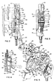
- FIGURE 2 is an elevational view as seen along the line 2-2 of FIG.1.
- FIGS. 3 and 4 are fragmentary cross-sections taken substantially along the lines 3-3 and 4-4, respectively, of FIG. 1
- FIG. 5 is an exploded perspective view of the primary components of the control.
- FIG. 6 is an enlarged view of certain components illustrated in FIG.1 and shows such components as positioned when the parking brake is in a fully released position.
- FIG. 7 is a view similar to FIG. 6 but shows the components as positioned when the pedal is initially depressed to apply the brake.
- FIG. 8 also is a view similar to FIG. 6 but shows the components as positioned during further application of the brake.
- FIG. 9 is another view similar to FIG. 6 but shows the components as positioned after the brake has been applied.
- For purposes of illustration, the invention has been shown in the drawings as incorporated in
control apparatus 10 for setting and releasing the parking brake of an automobile or other vehicle. The parking brake itself has been shown schematically by thebox 11 in FIG. 1 and includes rear braking elements which are forced into engagement with drums or rotors when force is applied to the braking elements via aflexible cable 13 which is connected to thecontrol 10. Return springs are associated with the braking elements and release the latter when the tensile force applied to the cable by the control is relieved. - The
parking brake control 10 includes a main supportingbracket 15 which is adapted to be attached by fasteners 16 (FIG. 2) to a fixedframe member 17 beneath the instrument panel of the vehicle. Acover 18 is attached to and spaced laterally from the bracket and coacts with the latter to define a housing for several components of the control. - Setting of the
parking brake 11 is effected in response to clockwise pivoting of an actuatinglever 20 which herein is in the form of a foot-operated pedal having anelongated arm 21 with arubber pad 22 on the lower end thereof. A rivet 23 (FIG.3) extends through thebracket 15, a generallycircular mounting plate 24 of thepedal 20, and thecover 18 and supports the pedal to turn about a laterally extending horizontal axis. Connected between the bracket and theplate 24 of the pedal is acontractile spring 25 which urges the pedal to turn counterclockwise about therivet 23 and to a brake-released position shown in solid lines of Fig.1. When the pedal is in its released position, the upper side of thearm 21 engages and is stopped by arubber bumper 26 on thecover 18. - Clockwise turning of the
pedal 20 to a brake-applied position shown in phantom lines in FIG. 1 effects clockwise turning of atoothed sector 30 which pulls on thecable 13 to apply thebrake 11. Thesector 30 is supported to turn about therivet 23 and is in the form of a flat plate having an edge concentric with the rivet and formed with angularly spaced ratched teeth 31 (FIGS. 5 and 6). A rod-like connector 32 on the end of thecable 13 fits within a forked bracket 34 (FIG.5) which is secured rigidly to and projects from one side of the sector, the cable thus being fastened to the sector. - Drive means connect the
pedal 20 to thesector 30 and effect clockwise turning of the sector to a brake-applied position when the pedal is depressed clockwise to its brake-applied position. Herein, the drive means includes a toothed pawl 35 (FIG.6) which is supported to turn about arivet 36 on thearm 21 of the pedal. When thepedal 20 is first turned to its brake-applied position, the pawl is moved into engagement with one of theteeth 31 of thesector 30 and acts to drive the sector clockwise during further clockwise turning of the pedal. When thebrake 11 is released, the sector and the pedal turn counterclockwise in unison and the pawl remains in engagement with the sector until the pedal reaches its brake-released position. At that time, the pawl is kicked out of engagement with the sector. - To move the
pawl 35 into and out of engagement with thesector 30, the pawl is carried by a kicker plate 38 (FIG. 6) which also is supported to turn about therivet 36. Atorsion spring 39 is connected between thepedal 20 and atab 40 on the kicker plate and urges the pawl and the kicker plate clockwise thereby tending to place the pawl in engagement with the sector. When the pedal is in its fully released position, asecond tab 41 on the kicker plate engages alug 42 on thebracket 15 and forces the kicker plate and the pawl counterclockwise about therivet 36 to hold the pawl out of engagement with the sector. When the pedal is first turned toward its brake-applied position, thetab 41 moves away from thelug 42 to allow thespring 39 to pivot the pawl clockwise into driving engagement with the sector and thereby cause the sector to turn clockwise with the pedal. Upon release of thebrake 11, the sector rotates past the pawl as the sector is turned counterclockwise by the brake return springs acting through thecable 13 and as the pedal is turned counterclockwise by thecontractile spring 25. When the pedal reaches its released position, thetab 41 of thekicker plate 38 engages thelug 42 of thebraket 15 to pivot the pawl out of engagement with the sector and release the sector from the pedal. - As the
sector 30 is turned clockwise toward its brake-applied position, it ratchets past a second pawl 45 (FIG. 5) which engages the sector and holds the sector in its brake-applied position once clockwise turning of the sector is stopped and thebrake 11 is set. As will become apparent subsequently, theholding pawl 45 is released automatically from thesector 30 when thepedal 20 is next pushed toward its brake-applied position and thus thecontrol 10 is of the so-called push-to-release type. As also will become apparent subsequently, theholding pawl 45 of the push-to-release control 10 is located out of engagement with thesector 30 when the sector and the pedal are in their brake-released positions. - In accordance with one aspect of the present invention, the push-to-
release control 10 with itssingle toothed sector 30 is also self-adjusting following installation of the control in the vehicle in that, once thecable 13 has been hooked to the sector, the sector automatically moves to a position to take up slack in the cable and place the cable and the return springs of thebrake 11 under a specified preload. For this purpose,a heavy spirally wound torsion spring 47 (FIGS. 4and 5) acts against the sector and tends to urge the sector to turn clockwise toward its brake-applied position. During installation of the control, however, the sector is locked against being turned by the spring. Once thecable 13 has been hooked to the sector, the latter is released to the action of thetorsion spring 47 and is turned clockwise until the forces exerted on the cable by the torsion spring and the return springs of thebrake 11 are equalized. - More specifically, the
spring 47 is made of flat spring steel wound into a spiral and sandwiched between thesector 30 and the generallycircular plate 24 which forms part of thepedal 20. One bent end 48 (FIG.6) of the spring is hooked around atab 49 which is struck form theplate 24. The otherbent end 50 of the spring is hooked around apin 51 extending laterally fom thebracket 34 on the sector. The spring is wound in a direction urging the sector toward its brake-applied position and urging the pedal toward its brake-released position. - Once the
spring 47 has been wound and attached to thepedal 20 and thesector 30, it is temporarily prevented from rotating the sector toward its brake applied position. For this purpose, a pin 53 (FIG. 4) with a generally C-shapedhead 54 is inserted through holes in thecover 18, thesector 30 and thebracket 15. As a result, the pin prevents the sector from rotating under the force of thespring 47. Initially, thetorsion spring 47 acts together with thecontractile spring 25 to urge the pedal 20 to its brake-released position with thearm 21 of the pedal in engagement with thebumper 26. - The
pin 53 remains in place during shipping and installation of thecontrol 10. After attachment of thebracket 15 to theframe 17 and after connection of thecable 13 to thesector 30, the pin is removed as shown in phantom lines in FIG. 4. This releases the sector for turning to its brake-applied position under the force of thespring 47. Since both the drivingpawl 35 and holdingpawl 45 are out of engagement with the sector when thepedal 20 is in its released position, such pawls do not interfere with turning of the sector by thespring 47 and relative to the pedal. The spring drives the sector until all slack in thecable 13 has been taken up and until further turning of the sector is stopped by the return springs of thebrake 11. The cable and the return springs thus are preloaded to an extent determinated by the preload placed in thespring 47. - If the
brake 11 or thecable 13 requires servicing, the released pawls 35 and 45 permit the sector to be turned counterclockwise to a position allowing thepin 53 to be re-inserted so as to hold the sector during such servicing. - As shown most clearly in FIG. 5, the holding
pawl 45 includes asingle tooth 55 and is formed with anelongated slot 56 which enables the pawl to slide and pivot on arivet 57 secured to thebracket 15 and thecover 18. Also supported by therivet 57 and disposed in side-by-side relation with thepawl 45 is atoggle lever 60 which is formed with anelongated slot 61 for receiving the rivet. Theslot 61 is curved about the axis of a pin 63 (FIG. 6) extending laterally from thebracket 15 and pivotally supporting the toggle lever. Connected to thelever 60 is one leg of atoggle spring 65 whose other leg is connected to the holdingpawl 45. When thelever 60 is positioned as shown in FIG. 6, thespring 65 urges the lever clockwise about thepivot 63 and, at the same time, urges thepawl 45 counterclockwise about therivet 57 and tends to move thepawl tooth 55 out of engagement with thesector 30. When thelever 60 is pivoted counterclockwise to the position shown in FIG. 7, thespring 65 toggles overcenter and urges thepawl 45 clockwise about therivet 57 so as to force thepawl tooth 55 toward the sector. Thespring 65 toggles whenever the point of connection of the spring to thelever 60 passes across a line extending between therivet 57 and the point of connection of the spring to thepawl 45. - Formed integrally with and extending downwardly and laterally from the
lever 60 is aleg 67 which coacts with a toggle reset lever 70 (FIGS. 5 and 6) to cause thelever 60 to swing counterclockwise about thepivot 63 from the position shown in FIG. 6 to the position shown in FIG. 7 when thepedal 20 is first depressed toward its brake-applied position. The toggle resetlever 70 is pivotally supported by a rivet 71 (FIG. 6) on thecover 18, the rivet being received in a slightly elongated slot in the reset lever so as to enable limited sliding movement of the reset lever in a direction extending transversely of the rivet. Atorsion spring 72 on the rivet engages the reset lever and atab 73 on thecover 18 and urges the reset lever counterclockwise about the rivet and into engagement with anothertab 74 on the cover. - After the
control 10 has been installed and thepin 53 has been pulled, the components of the control are positioned as shown in FIG. 6 when theparking brake 11 is released and thepedal 20 and thesector 30 are in their brake-released positions. As shown, thereset lever 70 is held against counterclockwise turning by thetab 74. The right end of theslot 61 in thetoggle lever 60 engages therivet 57 to hold that lever against being pivoted clockwise by thetoggle spring 65. The toggle spring urges the holdingpawl 45 counterclockwise about therivet 57 and against astop tab 75 on thecover 18 and keeps thepawl tooth 55 out of engagement with thesector 30, the pawl being positioned such that the left end of theslot 56 bears against the shank of the rivet. Because thetoggle spring 65 holds the pawl out of engagement with the sector when thepedal 20 is in its released position, and because the drivingpawl 35 also is released from the sector, the sector is, as discussed previously, free to turn relative to the pedal when thepin 53 is pulled and releases the sector to the action of thespiral spring 47. - When the
pedal 20 is first depressed to engage thebrake 11, alug 77 on the pedal moves into engagement with anear 78 on thereset lever 70 as shown in FIG.7 and pivots the reset lever clockwise about therivet 71. As a result, the rest lever acts against theleg 67 of thetoggle lever 60 to pivot the latter counterclockwise about thepin 63 and cause thespring 65 to toggle overcenter. To promote the overcenter action, atab 79 on thelever 60 engages anear 80 on thepawl 45 and rocks the pawl clockwise about therivet 57. Once the spring toggles, it urges thepawl 45 clockwise about therivet 57 and forces thepawl tooth 55 toward thesector 30. At about the same time that thespring 65 toggles overcenter, thelug 77 of the pedal clears theear 78 of thereset lever 60 to allow thespring 72 to return that lever to its original position against thetab 74. - By virtue of the
pawl 45 being urged clockwise about therivet 57 by the toggled-overspring 65, thepawl tooth 55 engages thesector 30 and ratchets across theteeth 31 of the sector as the latter is driven to its brake-applied position by thepedal 20. When the pushing force on the pedal is stopped, thepawl tooth 55 engages one of theratchet teeth 31. The tension in thecable 13 tends to turn the sector counterclockwise and, as a result of such turning, thesector tooth 31 acts against thepawl tooth 55 to slide thepawl 45 from right-to-left along therivet 57 until the right end of theslot 56 in the pawl bottoms against the rivet. The pawl and the sector thus are stopped with the pawl serving to hold the sector in its brake-applied position. - As the
pawl 45 is slid from right-to-left on therivet 57 by thesector tooth 31, theear 80 on the pawl engages thetab 79 on thelever 60 and causes the lever to rock clockwise about thepin 63. As a result, thespring 65 toggles in the reverse direction as shown in FIG. 9 and tends to urge thepawl 45 away from thesector 30. Thepawl tooth 55, however, remains in holding engagement with thesector tooth 31 by virtue of the counterclockwise force exerted on the pawl tooth by the sector tooth. As a result, the sector is held in its brake-applied position even though thetoggle spring 65 is urging the pawl counterclockwise towards its released position. - When it is desired to release the
brake 11, thepedal 20 is pushed further in the brake-applying direction. This turns thesector 30 clockwise to release the counterclockwise pressure exerted by thesector tooth 31 against thepawl tooth 55. As a result, thetoggle spring 65 pivots thepawl 45 to its released position shown in FIG. 6 to allow the sector and the pedal to return to their released positions. As the pedal returns, thelug 77 of the pedal cams against theear 78 of thereset lever 70 and the latter slides a slight distance on therivet 71 to enable the lug to clear the ear and return to the position of FIG.1. - Advantageously, a variable ratio cam 90 (FIG.6) is utilized to create a varying mechanical advantage and reduce the manual force required to be exerted on the pedal as the
brake 11 is fully applied. In this instance, the cam is a curved member which engages thecable 13 adjacent theconnector 32 and which is integral with a mountingplate 91 secured rigidly to the pedal. As the pedal is turned to its brake-applied position, the cable wraps around the cam to provide a mechanical advantage amplifying the force applied to the pedal and lowering the manual effort required to set thebrake 11. The tension in the cable acts against the cam to hold the pedal in its brake-applied position until thesector 30 is released to relieve the tension. - Since the
cam 90 is carried by the pedal, it may be of variable ratio so as to produce a mechanical advantage which becomes progressively greater as the pedal is pushed progressively further toward its brake-applied position. Thus, the radial distance between the active surface of the cam and thepivot axis 23 of the pedal is relatively large at the point where thecable 13 first engages the cam when the brake is released and becomes progressively smaller as the cam surface proceeds in a counterclockwise direction. Accordingly, when the pedal is first depressed and the clamp load of thebrake 11 is relatively small, the mechanical advantage is relatively small, and movement of the pedal through a given distance produces substantial movement of the cable. As the pedal is depressed further and the clamp load becomes higher, thecam 90 causes the cable travel to decrease for a given movement of the pedal and thus causes the mechanical advantage to increase. In this way, the pedal may be moved through its entire range with increasing mechanical advantage rather than requiring significantly greater effort as the brake becomes more fully set and the clamp load increases. - From the foregoing, it will be apparent that the present invention brings to the art a new and improved
parking brake control 10 having but asingle sector 30 but having both self-adjust and push-to-release capability. In addition, with thecam 90 being carried by the pedal 20 rather than by the sector, a progressively increasing mechanical advantage is obtained by the self-adjusting control as thebrake 11 is progressively applied.
Claims (2)
- Apparatus (10) for applying and releasing a vehicular parking brake (11) having an operating cable (13), said apparatus (10) comprising a mounting bracket (15), a toothed sector (30) adapted for connection to said cable (13), an operating lever (20), said sector (30) and said lever (20) being supported on said bracket (15) to turn about a predetermined axis (23) between brake-released positions and brake-applied positions, drive means (31, 35) for turning said sector (30) towards its brake-applied position when said lever (20) is turned toward its brake-applied position, a pawl (45) movably supported on said bracket (15) and having a tooth (55) selectively engageable with said sector (30) to hold said sector (30) in its brake-applied position, said tooth (55) being movable out of engagement with said sector (30) to free said sector (30) and said lever (20) for movement to said brake-released positions, said drive means (31, 35) and said pawl (45) permitting said sector (30) to turn relative to said lever (20) and toward its brake-applied position when said lever (20) is in its brake-released position, a torsion spring (47) connected to said sector (30) and urging said sector (30) toward its brake-applied position, means (60, 65, 70, 77) acting on said pawl (45) for (A) holding said tooth (55) out of engagement with said sector (30) when said lever (20) is in its brake-released position, (B) releasing said tooth (55) for movement into engagement with said sector (30) as an incident to initial movement of said lever (20) toward its brake-applied position, (C) urging said tooth (55) into ratcheting engagement with said sector (30) during continued movement of said lever (20) toward its brake-applied position and (D) urging said tooth (55) toward a position out of engagement with said sector (30) after movement of said lever (20) toward its brake-applied position is stopped whereby said tooth (55) moves out of engagement with said sector (30) as an incident to the next movement of said lever (20) toward its brake-applied position, means (53) temporarily fixing said sector (30) against rotation when said lever (20) is in its brake-released position and preventing said spring (47) from turning said sector (30) relative to said lever (20) and toward its brake-applied position, said fixing means (53) being releasable after connection of said cable (13) to said sector (30) thereby to enable said spring (47) to turn said sector (30) relative to said lever (20) and toward its brake-applied position to apply a tensioning force to said cable (13), said apparatus (10) being characterized in that said sector (30) is the only toothed sector of said apparatus (10) and in that said fixing means (53) comprise a removable pin connected between said sector (30) and said bracket (15) and preventing rotation of said sector (30) relative to said bracket (15).
- Apparatus (10) as claimed in claim 1 further including cam means (90) on said lever (20) and having a surface engageable with said cable (13) when said lever (20) is turned toward said brake-applied position, said cam surface being curved about said axis (23) and having a progressively changing radius.
Applications Claiming Priority (2)
| Application Number | Priority Date | Filing Date | Title |
|---|---|---|---|
| US743270 | 1991-08-09 | ||
| US07/743,270 US5217094A (en) | 1991-08-09 | 1991-08-09 | Self-adjusting, push-to-release parking brake control |
Publications (2)
| Publication Number | Publication Date |
|---|---|
| EP0527518A1 EP0527518A1 (en) | 1993-02-17 |
| EP0527518B1 true EP0527518B1 (en) | 1995-05-24 |
Family
ID=24988151
Family Applications (1)
| Application Number | Title | Priority Date | Filing Date |
|---|---|---|---|
| EP92202246A Expired - Lifetime EP0527518B1 (en) | 1991-08-09 | 1992-07-22 | Self-adjusting, push to-release parking brake |
Country Status (4)
| Country | Link |
|---|---|
| US (1) | US5217094A (en) |
| EP (1) | EP0527518B1 (en) |
| DE (1) | DE69202646T2 (en) |
| MX (1) | MX9204444A (en) |
Families Citing this family (37)
| Publication number | Priority date | Publication date | Assignee | Title |
|---|---|---|---|---|
| US5385068A (en) * | 1992-12-18 | 1995-01-31 | Cts Corporation | Electronic accelerator pedal assembly with pedal force sensor |
| US5477746A (en) * | 1994-03-21 | 1995-12-26 | Dura Automotive Systems, Inc. | Parking brake lever mechanism with lobe motion amplifying means |
| JP3669009B2 (en) * | 1995-07-20 | 2005-07-06 | アイシン精機株式会社 | Vehicle foot-operated parking brake control device |
| US5832784A (en) * | 1997-03-18 | 1998-11-10 | Dura Automotive Systems, Inc. | Variable ratio parking brake control with enhanced cable take-up |
| SE518099C2 (en) | 1997-11-21 | 2002-08-27 | Claes Johansson Automotive Ab | Adjustable pedal rack for a vehicle |
| JP3015349B1 (en) | 1998-09-04 | 2000-03-06 | ヒルタ工業株式会社 | Foot-operated parking brake pedal |
| US6237731B1 (en) | 1998-10-09 | 2001-05-29 | Ventra Group Inc. | Parking brake actuating assembly with brake cable positioning bracket |
| US6286389B1 (en) | 1999-01-21 | 2001-09-11 | Ventra Group Inc. | Parking brake actuating assembly with improved lockout structure |
| JP2001071875A (en) | 1999-06-28 | 2001-03-21 | Kuroishi Tekko Kk | Parking brake device for vehicle |
| US6282980B1 (en) | 1999-09-23 | 2001-09-04 | Ventra Group Inc. | Self-adjusting parking brake actuator |
| US6415681B1 (en) | 1999-11-17 | 2002-07-09 | Orscheln Products Llc | Pedal assembly |
| JP2001233188A (en) | 2000-02-25 | 2001-08-28 | Kuroishi Tekko Kk | Parking brake device for vehicle |
| JP3772666B2 (en) * | 2000-11-21 | 2006-05-10 | アイシン精機株式会社 | Vehicle foot-operated parking brake device |
| DE10101363C1 (en) * | 2001-01-13 | 2002-10-02 | Zf Sachs Ag | Parking lock actuation device for a parking lock device of a motor vehicle |
| KR100395329B1 (en) * | 2001-08-16 | 2003-08-21 | 기아자동차주식회사 | Brake System of Vehicles |
| US6609595B2 (en) | 2001-10-09 | 2003-08-26 | Dura Global Technologies, Inc. | Electric parking brake with direct tension feedback |
| DE10151475B4 (en) | 2001-10-18 | 2006-03-02 | Fico Cables, S.A., Rubi | Device for actuating vehicle brakes |
| DE10217471B4 (en) * | 2002-04-19 | 2006-02-02 | Daimlerchrysler Ag | Device for automatic adjustment of the cable tension of a cable |
| US7090602B2 (en) * | 2002-07-05 | 2006-08-15 | Shimano, Inc. | Assisting apparatus for changing speeds in a bicycle transmission |
| US6868752B2 (en) * | 2002-07-05 | 2005-03-22 | Shimano, Inc. | Assisting apparatus for changing speeds in a bicycle transmission |
| FR2853293A1 (en) * | 2003-04-02 | 2004-10-08 | Bowden | Mechanical parking brake control handle for use in vehicle, has latch of lever blocking mechanism movable between active and inactive blocking positions of lever by application force by parking brake on lever |
| US8048688B2 (en) * | 2006-10-24 | 2011-11-01 | Samsung Electronics Co., Ltd. | Method and apparatus for evaluation and improvement of mechanical and thermal properties of CNT/CNF arrays |
| US7477527B2 (en) * | 2005-03-21 | 2009-01-13 | Nanoconduction, Inc. | Apparatus for attaching a cooling structure to an integrated circuit |
| US7732918B2 (en) * | 2003-08-25 | 2010-06-08 | Nanoconduction, Inc. | Vapor chamber heat sink having a carbon nanotube fluid interface |
| US20070114658A1 (en) * | 2004-08-24 | 2007-05-24 | Carlos Dangelo | Integrated Circuit Micro-Cooler with Double-Sided Tubes of a CNT Array |
| US7538422B2 (en) * | 2003-08-25 | 2009-05-26 | Nanoconduction Inc. | Integrated circuit micro-cooler having multi-layers of tubes of a CNT array |
| US7109581B2 (en) * | 2003-08-25 | 2006-09-19 | Nanoconduction, Inc. | System and method using self-assembled nano structures in the design and fabrication of an integrated circuit micro-cooler |
| JP4391795B2 (en) * | 2003-10-10 | 2009-12-24 | 本田技研工業株式会社 | Arrangement structure of parking lever for two-wheeled vehicle and three-wheeled vehicle |
| KR100461609B1 (en) * | 2003-10-30 | 2004-12-13 | 경창산업주식회사 | Parking Brake Comprising Mechanism for Adjusting Brake Cable Tension |
| US7051614B2 (en) * | 2003-11-25 | 2006-05-30 | Intier Automotive Closures Inc. | Quiet apply push to release parking brake pedal |
| JP4152344B2 (en) * | 2004-05-12 | 2008-09-17 | 本田技研工業株式会社 | Manual brake device |
| US7472624B2 (en) * | 2004-07-07 | 2009-01-06 | Ventra Group Inc. | Push to release brake actuating assembly for a vehicle |
| JP4590230B2 (en) * | 2004-08-24 | 2010-12-01 | 本田技研工業株式会社 | Stepping parking brake device |
| US20070097648A1 (en) * | 2005-11-01 | 2007-05-03 | Kevin Xu | Method and apparatus for establishing optimal thermal contact between opposing surfaces |
| US20070227288A1 (en) * | 2006-03-14 | 2007-10-04 | Ferenc Anthony S | Push-to-release foot brake with eccentric torsion-lock self adjust mechanism |
| KR101480609B1 (en) * | 2013-05-14 | 2015-01-08 | 현대자동차주식회사 | Parking Pedal Assembly With Variable Pedal Ratio |
| US9845083B2 (en) | 2015-07-01 | 2017-12-19 | Dura Operating, Llc | Park brake control assembly |
Family Cites Families (6)
| Publication number | Priority date | Publication date | Assignee | Title |
|---|---|---|---|---|
| US3875820A (en) * | 1974-01-21 | 1975-04-08 | Gen Motors Corp | Vehicle parkings brake power operator |
| JPS5647339A (en) * | 1979-09-20 | 1981-04-30 | Nissan Motor Co Ltd | Pedal type parking brake device |
| US4570508A (en) * | 1984-06-08 | 1986-02-18 | General Motors Corporation | Multi-stroke parking brake variable ratio apply and release mechanism |
| US4872368A (en) * | 1988-07-28 | 1989-10-10 | Orscheln Co. | Push-to-release cable operating apparatus |
| US4841798A (en) * | 1988-08-30 | 1989-06-27 | Orscheln Co. | Foot-operated self-adjusting parking brake apparatus with controlled flyback |
| US5001942A (en) * | 1990-02-27 | 1991-03-26 | Orscheln Co. | Cable operating apparatus including a pocketed pawl |
-
1991
- 1991-08-09 US US07/743,270 patent/US5217094A/en not_active Expired - Fee Related
-
1992
- 1992-07-22 EP EP92202246A patent/EP0527518B1/en not_active Expired - Lifetime
- 1992-07-22 DE DE69202646T patent/DE69202646T2/en not_active Expired - Fee Related
- 1992-07-30 MX MX9204444A patent/MX9204444A/en not_active IP Right Cessation
Also Published As
| Publication number | Publication date |
|---|---|
| EP0527518A1 (en) | 1993-02-17 |
| MX9204444A (en) | 1993-02-01 |
| US5217094A (en) | 1993-06-08 |
| DE69202646T2 (en) | 1995-10-19 |
| DE69202646D1 (en) | 1995-06-29 |
Similar Documents
| Publication | Publication Date | Title |
|---|---|---|
| US5217094A (en) | Self-adjusting, push-to-release parking brake control | |
| US4819501A (en) | Self-adjusting brake mechanism | |
| US5211072A (en) | Variable ratio park brake with slack adjust | |
| US4854187A (en) | Hand brake assembly for a vehicle | |
| US4864886A (en) | Console integrated pull to release parking brake actuator | |
| US5467666A (en) | Non-jamming self-adjust pawl and ratchet mechanism | |
| KR970705490A (en) | CABLE SLACK ADJUSTER | |
| GB2072776A (en) | Parking brake cable adjusting device | |
| EP0351131B1 (en) | Automobile cable brake mechanism | |
| US6282980B1 (en) | Self-adjusting parking brake actuator | |
| US5816111A (en) | Actuator for a hand brake of a motor vehicle | |
| KR100461609B1 (en) | Parking Brake Comprising Mechanism for Adjusting Brake Cable Tension | |
| EP0164231B1 (en) | Parking brake mechanism | |
| CA2377009A1 (en) | Parking brake device for vehicle | |
| EP1752347B1 (en) | Ratchet type parking brake having quiet operation | |
| US5054333A (en) | Movable pedal lever stop | |
| US5528956A (en) | Vehicular parking brake control with stored energy assist for applying the brake | |
| US6880426B2 (en) | Parking brake for a motor vehicle | |
| CA2488604C (en) | Quiet apply push to release parking brake pedal | |
| US2899838A (en) | Delayed action brake release s | |
| US3648541A (en) | Emergency brake with toggle lock pawl | |
| US6736025B2 (en) | Vehicular foot-operated parking brake control apparatus | |
| US3077790A (en) | Cable brake for trucks | |
| US20070227288A1 (en) | Push-to-release foot brake with eccentric torsion-lock self adjust mechanism | |
| KR200167752Y1 (en) | Automated tension control device of parking brake cable |
Legal Events
| Date | Code | Title | Description |
|---|---|---|---|
| PUAI | Public reference made under article 153(3) epc to a published international application that has entered the european phase |
Free format text: ORIGINAL CODE: 0009012 |
|
| AK | Designated contracting states |
Kind code of ref document: A1 Designated state(s): DE FR GB IT |
|
| 17P | Request for examination filed |
Effective date: 19930803 |
|
| 17Q | First examination report despatched |
Effective date: 19940614 |
|
| GRAA | (expected) grant |
Free format text: ORIGINAL CODE: 0009210 |
|
| AK | Designated contracting states |
Kind code of ref document: B1 Designated state(s): DE FR GB IT |
|
| ITF | It: translation for a ep patent filed | ||
| REF | Corresponds to: |
Ref document number: 69202646 Country of ref document: DE Date of ref document: 19950629 |
|
| ET | Fr: translation filed | ||
| PLBE | No opposition filed within time limit |
Free format text: ORIGINAL CODE: 0009261 |
|
| 26N | No opposition filed | ||
| PGFP | Annual fee paid to national office [announced via postgrant information from national office to epo] |
Ref country code: FR Payment date: 19980709 Year of fee payment: 7 |
|
| PGFP | Annual fee paid to national office [announced via postgrant information from national office to epo] |
Ref country code: GB Payment date: 19980713 Year of fee payment: 7 |
|
| PGFP | Annual fee paid to national office [announced via postgrant information from national office to epo] |
Ref country code: DE Payment date: 19980803 Year of fee payment: 7 |
|
| PG25 | Lapsed in a contracting state [announced via postgrant information from national office to epo] |
Ref country code: GB Free format text: LAPSE BECAUSE OF NON-PAYMENT OF DUE FEES Effective date: 19990722 |
|
| PG25 | Lapsed in a contracting state [announced via postgrant information from national office to epo] |
Ref country code: FR Free format text: THE PATENT HAS BEEN ANNULLED BY A DECISION OF A NATIONAL AUTHORITY Effective date: 19990731 |
|
| GBPC | Gb: european patent ceased through non-payment of renewal fee |
Effective date: 19990722 |
|
| PG25 | Lapsed in a contracting state [announced via postgrant information from national office to epo] |
Ref country code: DE Free format text: LAPSE BECAUSE OF NON-PAYMENT OF DUE FEES Effective date: 20000503 |
|
| REG | Reference to a national code |
Ref country code: FR Ref legal event code: ST |
|
| PG25 | Lapsed in a contracting state [announced via postgrant information from national office to epo] |
Ref country code: IT Free format text: LAPSE BECAUSE OF NON-PAYMENT OF DUE FEES;WARNING: LAPSES OF ITALIAN PATENTS WITH EFFECTIVE DATE BEFORE 2007 MAY HAVE OCCURRED AT ANY TIME BEFORE 2007. THE CORRECT EFFECTIVE DATE MAY BE DIFFERENT FROM THE ONE RECORDED. Effective date: 20050722 |