EP0527361B1 - Hydraulically damping dual-chamber engine mount - Google Patents
Hydraulically damping dual-chamber engine mount Download PDFInfo
- Publication number
- EP0527361B1 EP0527361B1 EP92112447A EP92112447A EP0527361B1 EP 0527361 B1 EP0527361 B1 EP 0527361B1 EP 92112447 A EP92112447 A EP 92112447A EP 92112447 A EP92112447 A EP 92112447A EP 0527361 B1 EP0527361 B1 EP 0527361B1
- Authority
- EP
- European Patent Office
- Prior art keywords
- engine mount
- dual
- chamber engine
- duct
- mount according
- Prior art date
- Legal status (The legal status is an assumption and is not a legal conclusion. Google has not performed a legal analysis and makes no representation as to the accuracy of the status listed.)
- Expired - Lifetime
Links
Images
Classifications
-
- F—MECHANICAL ENGINEERING; LIGHTING; HEATING; WEAPONS; BLASTING
- F16—ENGINEERING ELEMENTS AND UNITS; GENERAL MEASURES FOR PRODUCING AND MAINTAINING EFFECTIVE FUNCTIONING OF MACHINES OR INSTALLATIONS; THERMAL INSULATION IN GENERAL
- F16F—SPRINGS; SHOCK-ABSORBERS; MEANS FOR DAMPING VIBRATION
- F16F13/00—Units comprising springs of the non-fluid type as well as vibration-dampers, shock-absorbers, or fluid springs
- F16F13/04—Units comprising springs of the non-fluid type as well as vibration-dampers, shock-absorbers, or fluid springs comprising both a plastics spring and a damper, e.g. a friction damper
- F16F13/06—Units comprising springs of the non-fluid type as well as vibration-dampers, shock-absorbers, or fluid springs comprising both a plastics spring and a damper, e.g. a friction damper the damper being a fluid damper, e.g. the plastics spring not forming a part of the wall of the fluid chamber of the damper
- F16F13/08—Units comprising springs of the non-fluid type as well as vibration-dampers, shock-absorbers, or fluid springs comprising both a plastics spring and a damper, e.g. a friction damper the damper being a fluid damper, e.g. the plastics spring not forming a part of the wall of the fluid chamber of the damper the plastics spring forming at least a part of the wall of the fluid chamber of the damper
- F16F13/10—Units comprising springs of the non-fluid type as well as vibration-dampers, shock-absorbers, or fluid springs comprising both a plastics spring and a damper, e.g. a friction damper the damper being a fluid damper, e.g. the plastics spring not forming a part of the wall of the fluid chamber of the damper the plastics spring forming at least a part of the wall of the fluid chamber of the damper the wall being at least in part formed by a flexible membrane or the like
- F16F13/105—Units comprising springs of the non-fluid type as well as vibration-dampers, shock-absorbers, or fluid springs comprising both a plastics spring and a damper, e.g. a friction damper the damper being a fluid damper, e.g. the plastics spring not forming a part of the wall of the fluid chamber of the damper the plastics spring forming at least a part of the wall of the fluid chamber of the damper the wall being at least in part formed by a flexible membrane or the like characterised by features of partitions between two working chambers
Definitions
- the invention relates to a hydraulically damping two-chamber engine mount, the two chambers are rubber-elastic edged and between which a rigid intermediate plate with an overflow channel and a central, rigid membrane with a predetermined vertical clearance is arranged for decoupling high-frequency vibrations of small amplitudes.
- a bearing is intended in particular to dampen low-frequency vibrations and to isolate high-frequency vibrations, in particular acoustic vibrations.
- the requirements with regard to the damping and insulation properties of such a bearing consist, among other things, in that the damping effect and the insulating effect achieved can be optimized independently of one another and that the damping and insulating effect depend on the amplitude of the vibration introduced.
- this required effect is achieved by connecting a low-frequency tuned channel in parallel as a connection opening between the working and compensation chamber and the high-frequency tuned connection opening is closed by a membrane with a limited free path and thus the fluid exchange via this connection opening to a certain volume, which is down to zero can go limited.
- a translationally movable but rigid membrane of a hydraulic damping two-chamber engine mount according to the preamble of claim 1 is known from US-A-4,756,513.
- the rigid membrane is encased on the outer circumference by a rubber ring which is slidably supported in a corresponding recess in the rigid intermediate plate surrounding the membrane.
- the present invention has for its object to provide a membrane with limited clearance, which is simple in construction and in which an almost force-free movement is possible, i.e. a movement that can only freely follow the vibrations that have been initiated with very little external influence.
- an annular channel open to the chambers with a reduced cross-section on the top and bottom to limit the free path is provided by means of stops in which the rigid membrane rolls on at least one element of circular cross section on the respective opposite channel wall.
- This rolling mounting of the membrane creates a free mobility of the membrane, which is only subjected to very low frictional forces.
- the structure itself is very simple and the individual components can be manufactured using inexpensive manufacturing processes, since the required tolerances are within the usual range.
- the rolling element consists of an elastic ring which is inserted into the channel. This allows the membrane to roll easily on the ring, the free path of the membrane being limited by the reduced width of the channel on the top and bottom.
- the rolling elements can also consist of elastic ring segments, cylindrical rollers or balls.
- the channel has parallel walls that are tapered on the top and bottom.
- the channel walls are arched to each other.
- the radius of curvature of the channel walls should be at least twice as large as the radius of the elements used.
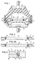
- Figure 1 shows a longitudinal section through a two-chamber engine mount, in which the working chamber 1 is bordered in a conventional manner by a truncated cone-shaped support spring 2, which supports the bearing plate 3 on the upper side with a bolt 4 for supporting the engine.
- a truncated cone-shaped support spring 2 which supports the bearing plate 3 on the upper side with a bolt 4 for supporting the engine.
- the compensation chamber 6 which is bounded by a flexible wall 7 below.
- Support spring 2 intermediate plate 5 and compensation chamber 7 are held together with the lower cup-shaped end plate 8, which is fixed to the body via a bolt 9, via an annular flange 10 as the outer wall.
- the intermediate plate 5 has in its outer circumferential area the overflow channel 11, which forms a connection between the working chamber 1 and the compensating chamber 6 via overflow openings, not shown, and is tuned for damping low-frequency vibrations of large amplitude.
- a rolling membrane 12 is now centrally mounted in the intermediate plate 5, the design and arrangement of which can be seen in detail and on an enlarged scale from FIG. 2.
- a channel 15 is left between the rigid membrane 12 and the intermediate plate 5, the channel walls 16 and 17 of which run parallel to one another in the central region and narrow conically at the upper and lower ends at a predetermined angle.
- An elastic ring 18 is now inserted in this channel 15, the diameter of which corresponds to the width of the channel 15 or can also be made slightly larger.
- the diaphragm plate 12 When vibrations are introduced, the diaphragm plate 12 can now be freely deflected up and down, the ring 18 rolling up and down on the channel walls 16 and 17, so that a lower end position of the diaphragm 12 can result, as can be seen in FIG it is shown in Figure 2a.
- the runway ie the channel walls 16 and 17 is designed in terms of its geometry such that the rolling path and thus the free path of the membrane 12 is limited.
- the ring 18 takes over the rolling function, seals the membrane 12 against the intermediate plate 5, can compensate for manufacturing tolerances and ensures a softer stop of the membrane 12 in its end positions.
- the intermediate plate 12 is formed in two parts and consists of a lower ring part 20 and an upper ring part 21, this horizontal division not necessarily having to take place in the center, as can also be seen from FIG. 2. This division also greatly facilitates assembly, since the ring 18 is first drawn onto the membrane 12 and then the parts 20 and 21 of the intermediate plate are placed on the outside.
- FIG. 3 Another possibility of designing the channel 15 is shown in FIG. 3.
- the channel walls 23 and 24 are arched to each other and expediently with a radius R that is at least twice as large as the radius of the ring 18.
- the rolling behavior of the ring 18 and the stop behavior of the membrane 12 can be further enhanced by such a design to be influenced.
Landscapes
- Engineering & Computer Science (AREA)
- General Engineering & Computer Science (AREA)
- Mechanical Engineering (AREA)
- Combined Devices Of Dampers And Springs (AREA)
- Arrangement Or Mounting Of Propulsion Units For Vehicles (AREA)
Description
Die Erfindung bezieht sich auf ein hydraulisch dämpfendes Zweikammer-Motorlager, dessen beide Kammern gummielastisch berandet sind und zwischen denen eine starre Zwischenplatte mit einem Überströmkanal und einer zentralen, starren Membran mit vorgegebenem vertikalem Freiweg zur Entkopplung hochfrequenter Schwingungen kleiner Amplituden angeordnet ist.
Mit einem solchen Lager sollen insbesondere niederfrequente Schwingungen gedämpft und hochfrequente Schwingungen, insbesondere akustische Schwingungen isoliert werden. Die Anforderungen bezüglich der Dämpfungs- und Isolationseigenschaften eines solchen Lagers bestehen u.a. darin, daß die erzielte Dämpfungswirkung und die erzielte Isolierwirkung unabhängig von einander optimiert werden können und daß die Dämpfungs- und Isolierwirkung von der Amplitude der eingeleiteten Schwingung abhängen.The invention relates to a hydraulically damping two-chamber engine mount, the two chambers are rubber-elastic edged and between which a rigid intermediate plate with an overflow channel and a central, rigid membrane with a predetermined vertical clearance is arranged for decoupling high-frequency vibrations of small amplitudes.
Such a bearing is intended in particular to dampen low-frequency vibrations and to isolate high-frequency vibrations, in particular acoustic vibrations. The requirements with regard to the damping and insulation properties of such a bearing consist, among other things, in that the damping effect and the insulating effect achieved can be optimized independently of one another and that the damping and insulating effect depend on the amplitude of the vibration introduced.
Im Grundprinzip wird diese geforderte Wirkung durch das Parallelschalten von einem niederfrequent abgestimmten Kanal als Verbindungsöffnung zwischen Arbeits- und Ausgleichskammer erreicht und die hochfrequent abgestimmte Verbindungsöffnung durch eine Membran mit begrenztem Freiweg verschlossen und somit der Flüssigkeitsaustausch über diese Verbindungsöffnung auf ein bestimmtes Volumen, das bis zu null gehen kann, beschränkt.In the basic principle, this required effect is achieved by connecting a low-frequency tuned channel in parallel as a connection opening between the working and compensation chamber and the high-frequency tuned connection opening is closed by a membrane with a limited free path and thus the fluid exchange via this connection opening to a certain volume, which is down to zero can go limited.
Nach dem Stande der Technik wurde das Problem, eine Membran mit begrenztem Freiweg zu schaffen, auf unterschiedliche Weise gelöst, wie das beispielsweise in der EP 0040290 B 1 der DE 3024089 C 2 oder der DE 3246587 C 2 beschrieben ist. Dabei haben sich im wesentlichen zwei Lösungen herausgebildet, die wie folgt zusammengefasst werden können. Einmal auf Biegung beanspruchte Membranen, die sich durch ihre Geometrie in ihrer Federkennlinie progressiv verhalten oder durch Anschläge wie zum Beispiel einen Membrankäfig, in ihrem Freiweg begrenzt sind. Dazu zählen auch starre Membranplatten, die durch eine biegeweiches Gelenk aufgehängt sind. Bei dieser Art der Membranen ist die Amplitudentrennung zwischen hochfrequenten und niederfrequenten Schwingungen oftmals unzureichend, da bei größeren Amplituden, d.h. höheren Differenzdrücken zwischen den Flüssigkeitskammern die Durchbiegung dieser Membran ebenfalls zunimmt. Darüber hinaus sind bei einer Freiwegbegrenzung enge Fertigungstoleranzen erforderlich, die im Bereich von zehntel Milimetern liegen. Eine Freiwegbegrenzung durch Anschläge kann darüberhinaus zu Geräuschentwicklungen führen.According to the prior art, the problem of creating a membrane with limited free travel has been solved in different ways, as is described, for example, in EP 0040290 B1 of DE 3024089 C2 or DE 3246587 C2. Essentially two solutions have emerged, which can be summarized as follows. Diaphragms that are once subjected to bending, have a progressive behavior due to their geometry in their spring characteristic or are limited in their free travel by stops such as a membrane cage. This also includes rigid membrane plates that are suspended by a flexible joint. With this type of membrane, the amplitude separation between high-frequency and low-frequency vibrations is often inadequate, since with larger amplitudes, i.e. higher differential pressures between the liquid chambers, the deflection of this membrane also increases. In addition, narrow manufacturing tolerances in the range of tenths of a millimeter are required for a free path limitation. A free path limitation by stops can also lead to noise.
Eine weiter Möglichkeit der Gestaltung dieser Membran besteht im translatorisch bewegten Membranplatten, die freifliegend zwischen zwei Anschlägen eingefaßt sind. Bei derartigen Membranen sind die Fertigungstoleranzen noch kritischer, da zusätzlich zur Freiwegtoleranz noch die Durchmessertoleranz der Membran und des Membrankäfigs genau eingehalten werden muß. Außerdem ist durch Reibungseffekte eine Art Loslöseffekt zu beobachten, eine Kraft, die erst überwunden werden muß, bevor sich die Membran in ihrem Käfig frei bewegen kann.Another possibility for the design of this membrane is in the translationally moved membrane plates, which are framed freely between two stops. In the case of such membranes, the manufacturing tolerances are even more critical since, in addition to the free travel tolerance, the diameter tolerance of the membrane and the membrane cage must also be strictly observed. In addition, a kind of detachment effect can be observed through friction effects, a force that must first be overcome before the membrane can move freely in its cage.
Eine translatorisch bewegbare, aber starre Membran eines hydraulisch dämpfenden Zweikammer-Motorlagers gemäß Oberbegriff des Anspruchs 1 ist aus der US-A-4 756 513 bekannt. Dabei ist die starre Membran jedoch am Außenumfang von einem Gummiring ummantelt, der in einer entsprechenden Ausnehmung der die Membran umgebenden starren Zwischenplatte verschieblich gehaltert ist. Mit einer solchen Ausgestaltung der Membran werden zwar Klappergeräusche beim Anschlagen an die obere und die untere Begrenzung vermieden, bei einer entsprechend dichten Führung sind jedoch auch hier erhebliche Reibungskräfte zu überwinden, so daß diese Membran nur eine unzureichende leichte Beweglichkeit aufweist.A translationally movable but rigid membrane of a hydraulic damping two-chamber engine mount according to the preamble of
Ausgehend von dem vorstehend genannten Stand der Technik liegt der vorliegenden Erfindung die Aufgabe zugrunde, eine Membran mit begrenztem Freiweg zu schaffen, die einfach aufgebaut ist und bei der eine nahezu kraftfreie Bewegung möglich ist, d.h. eine Bewegung, die nur mit äußerst geringen äußeren Einwirkungen frei den eingeleiteten Schwingungen folgen kann.Starting from the above-mentioned prior art, the present invention has for its object to provide a membrane with limited clearance, which is simple in construction and in which an almost force-free movement is possible, i.e. a movement that can only freely follow the vibrations that have been initiated with very little external influence.
Zur Lösung dieser Aufgabe ist erfindungsgemäß vorgesehen, daß zwischen der starren Membran und der diese ringfömrig umgebenden, starren Zwischenplatte ein ringförmiger, zu den Kammern hin offener Kanal mit ober- und unterseitig vermindertem Querschnitt zur Freiwegbegrenzung mittels Anschlägen vorgesehen ist, in dem auf der jeweiligen gegenüberliegenden Kanalwand die starre Membran auf mindestens einem Element kreisförmigen Querschnittes abrollt.To achieve this object, it is provided according to the invention that between the rigid membrane and the rigid intermediate plate surrounding it in the form of a ring, an annular channel open to the chambers with a reduced cross-section on the top and bottom to limit the free path is provided by means of stops in which the rigid membrane rolls on at least one element of circular cross section on the respective opposite channel wall.
Durch diese rollende Lagerung der Membran wird eine freie Beweglichkeit derselben geschaffen, die nur sehr geringen Reibungskräften unterworfen ist. Der Aufbau selbst ist sehr einfach und die einzelnen Bauteile können durch günstige Fertigungsverfahren hergestellt werden, da die geforderten Toleranzen im üblichen Rahmen liegen.This rolling mounting of the membrane creates a free mobility of the membrane, which is only subjected to very low frictional forces. The structure itself is very simple and the individual components can be manufactured using inexpensive manufacturing processes, since the required tolerances are within the usual range.
Als besonders zweckmäßig hat es sich erwiesen, wenn das abrollende Elemente aus einem elastischen Ring besteht, der in den Kanal eingesetzt ist. Damit kann die Membran leicht auf dem Ring abrollen, wobei durch die verminderte Breite des Kanals ober- und unterseitig der Freiweg der Membran begrenzt ist.It has proven particularly expedient if the rolling element consists of an elastic ring which is inserted into the channel. This allows the membrane to roll easily on the ring, the free path of the membrane being limited by the reduced width of the channel on the top and bottom.
Die abrollenden Elemente können aber auch aus elastischen Ringsegmenten, Zylinderrollen oder Kugeln bestehen.The rolling elements can also consist of elastic ring segments, cylindrical rollers or balls.
Zweckmäßig ist es, wenn der Kanal parallele Wandungen aufweist, die ober- und unterseitig konisch zulaufend ausgebildet sind.It is expedient if the channel has parallel walls that are tapered on the top and bottom.
Es ist aber auch möglich, daß die Kanalwandungen gewölbt zueinander verlaufen. Dabei sollte der Krümmungsradius der Kanalwandungen mindestens doppelt so groß sein, wie der Radius der eingesetzten Elemente.But it is also possible that the channel walls are arched to each other. The radius of curvature of the channel walls should be at least twice as large as the radius of the elements used.
Insbesondere zur Erleichterung der Montage ist es zweckmäßig, wenn die Zwischenplatte horizontal geteilt ist. An Hand ein schematischen Zeichnung sind Aufbau und Funktionsweise eines Ausführungsbeispiels nach der Erfindung näher erläutert. Dabei zeigen
- Fig. 1
- einen Querschnitt durch ein Motorlager mit Rollmembran
- Fig. 2
- einen vergrößerten Auschnitt der Zwischenplatte mit der Rollmembran und
- Fig. 3
- eine spezielle Gestaltung des Abrollkanals.
- Fig. 1
- a cross section through an engine mount with a rolling membrane
- Fig. 2
- an enlarged section of the intermediate plate with the rolling membrane and
- Fig. 3
- a special design of the rolling channel.
Figur 1 zeigt einen Längsschnitt durch ein Zweikammer-Motorlager, bei dem in herkömmlicher Weise die Arbeitskammer 1 von einer kegelstumpfförmigen Tragfeder 2 berandet ist, die oberseitig die Lagerplatte 3 mit einem Bolzen 4 zur Abstützung des Motors trägt. Unterhalb der Zwischenplatte 5 liegt die Ausgleichskammer 6, die von einer flexiblen Wandung 7 nach unter begrenzt ist. Tragfeder 2, Zwischenplatte 5 und Ausgleichskammer 7 werden zusammen mit der unteren topfförmigen Abschlußplatte 8, die über einen Bolzen 9 an der Karosserie festgelegt ist über einen Ringflansch 10 als Außenwandung zusammengehalten.Figure 1 shows a longitudinal section through a two-chamber engine mount, in which the
Die Zwischenplatte 5 weist in ihrem äußerem Umfangsbereich den Überstromkanal 11 auf, der über nicht dargestellte Überströmöffnungen eine Verbindung zwischen der Arbeitskammer 1 und der Ausgleichskammer 6 bildet und zur Dämpfung niederfrequenter Schwingungen großer Amplitude abgestimmt ist.The
Zentral in der Zwischenplatte 5 ist nunmehr eine Rollmembran 12 gelagert, deren Ausbildung und Anordnung im Einzelnen und im vergrößerten Maßstab aus Figur 2 ersichtlich ist.A
Zwischen der starren Membran 12 und der Zwischenplatte 5 ist ein Kanal 15 freigelassen, dessen Kanalwandungen 16 und 17 im mittleren Bereich parallel zueinander verlaufen und sich am oberen und unteren Ende unter einem vorgegeben Winkel alpha konisch verengen. In diesem Kanal 15 ist nunmehr ein elastischer Ring 18 eingesetzt, dessen Durchmesser der Breite des Kanals 15 entspricht oder aber auch geringfügig größer ausgebildet sein kann.A
Bei der Einleitung von Schwingungen kann nunmehr die Membranplatte 12 frei nach oben und unten ausgelenkt werden, wobei der Ring 18 auf den Kanalwänden 16 und 17 nach oben bzw. nach unten rollt, sodaß sich in etwa eine untere Endstellung der Membran 12 ergeben kann, wie sie in Figur 2a dargestellt ist.When vibrations are introduced, the
Wie sich aus der Zeichnung ergibt, ist die Rollbahn, d.h. die Kanalwandungen 16 und 17 von ihrer Geometrie her so ausgebildet, daß der Abrollweg und damit der Freiweg der Membran 12 begrenzt ist. Der Ring 18 übernimmt dabei die Abrollfunktion, dichtet die Membran 12 gegen die Zwischenplatte 5 ab, kann Fertigungstoleranzen ausgleichen und sorgt für einen weicheren Anschlag der Membran 12 in ihren Endstellungen.As can be seen from the drawing, the runway, ie the
Zweckmäßig ist es ferner, wenn die Zwischenplatte 12 zweiteilig ausgebildet ist und aus einem unterem Ringteil 20 und einem oberen Ringteil 21 besteht, wobei diese horizontale Teilung nicht unbedingt mittig erfolgen muß, wie man das auch aus Figur 2 ersieht. Durch diese Teilung wird auch die Montage wesentlich erleichtert, da zunächst auf die Membran 12 der Ring 18 aufgezogen und anschließend die Teile 20 und 21 der Zwischenplatte außen aufgesetzt werden.It is also expedient if the
Eine weitere Möglichkeit der Gestaltung des Kanals 15 ist in Figur 3 gezeigt. Dabei sind die Kanalwandungen 23 und 24 zueinander gewölbt ausgeführt und zwar zweckmäßigerweise mit einem Radius R, der mindestens doppelt so groß ist, wie der Radius des Ringes 18. Durch eine solche Gestaltung kann das Abrollverhalten des Ringes 18 und das Anschlagsverhalten der Membran 12 noch weiter beeinflußt werden.Another possibility of designing the
Mit der beschriebenen Gestaltung ergibt sich also ein Zweikammer-Motorlager mit einer Membran zur Isolierung hochfrequenter Schwingungen kleiner Amplitude, wobei die Membran praktisch kraftfrei den eingeleiteten Schwingungen folgen kann und damit eine optimale Dämpfung bewirkt.The design described thus results in a two-chamber engine mount with a membrane for isolating high-frequency vibrations of small amplitude, the membrane being able to follow the vibrations introduced with practically no force and thus effecting optimal damping.
Claims (9)
- Hydraulically damping dual-chamber engine mount, whose two chambers are rubber-elastically edged and comprise between them a rigid intermediate plate with an overflow duct and a central, rigid diaphragm with a given vertical freedom of movement for decoupling high frequency vibrations of low amplitude, characterised in that an annular duct (15) is provided between the rigid diaphragm (11) and the rigid intermediate plate (5) annularly surrounding the rigid diaphragm, which annular duct (15) opens into the chambers (1, 6) and has a reduced cross section on its upper and lower sides to limit the freedom of movement by means of stops, the rigid diaphragm (11) rolling during its vertical movement upon at least one element (18) having a circular cross section in the duct (15) on the duct wall (17; 24) provided on the intermediate plate (5).
- Dual-chamber engine mount according to claim 1, characterised in that the rolling element is formed by an elastic ring (18).
- Dual-chamber engine mount according to claim 1, characterised in that the elements are made of elastic annular segments.
- Dual-chamber engine mount according to claim 1, characterised in that the elements are formed by cylindrical rollers.
- Dual-chamber engine mount according to claim 1, characterised in that the elements are formed by balls.
- Dual-chamber engine mount according to claim 1, characterised in that the duct (15) comprises parallel walls (16, 17), which converge conically on the upper and lower sides.
- Dual-chamber engine mount according to claim 1, characterised in that the duct walls (23, 24) converge in an arc.
- Dual-chamber engine mount according to claim 7, characterised in that the radius of curvature of the duct walls (23, 24) is at least twice as great as the radius of the elements (18) used.
- Dual-chamber engine mount according to one or more of claims 1 to 8, characterised in that the intermediate plate (5) is divided horizontally.
Applications Claiming Priority (2)
| Application Number | Priority Date | Filing Date | Title |
|---|---|---|---|
| DE4126769 | 1991-08-13 | ||
| DE4126769A DE4126769C1 (en) | 1991-08-13 | 1991-08-13 |
Publications (2)
| Publication Number | Publication Date |
|---|---|
| EP0527361A1 EP0527361A1 (en) | 1993-02-17 |
| EP0527361B1 true EP0527361B1 (en) | 1994-10-05 |
Family
ID=6438221
Family Applications (1)
| Application Number | Title | Priority Date | Filing Date |
|---|---|---|---|
| EP92112447A Expired - Lifetime EP0527361B1 (en) | 1991-08-13 | 1992-07-21 | Hydraulically damping dual-chamber engine mount |
Country Status (5)
| Country | Link |
|---|---|
| US (1) | US5295672A (en) |
| EP (1) | EP0527361B1 (en) |
| JP (1) | JPH05202978A (en) |
| DE (2) | DE4126769C1 (en) |
| ES (1) | ES2062855T3 (en) |
Families Citing this family (10)
| Publication number | Priority date | Publication date | Assignee | Title |
|---|---|---|---|---|
| FR2714947B1 (en) * | 1994-01-11 | 1996-03-29 | Hutchinson | Improvements to hydraulic anti-vibration devices. |
| US5704598A (en) * | 1995-09-12 | 1998-01-06 | Bridgestone Corporation | Vibration isolating apparatus |
| US6412761B1 (en) * | 2001-04-25 | 2002-07-02 | Delphi Technologies, Inc. | Hybrid hydraulic mount with magnetorheological fluid chamber |
| DE10215237A1 (en) * | 2002-04-06 | 2003-10-16 | Stihl Maschf Andreas | Hand-held motor-driven work tool |
| JP3989482B2 (en) * | 2004-11-04 | 2007-10-10 | 本田技研工業株式会社 | Vibration isolator |
| JP4060309B2 (en) * | 2004-11-04 | 2008-03-12 | 本田技研工業株式会社 | Vibration isolator for vehicle |
| KR101424700B1 (en) * | 2012-12-11 | 2014-08-01 | 안영공 | Mount using Negative Spring |
| JP6300404B2 (en) * | 2014-04-09 | 2018-03-28 | 株式会社ブリヂストン | Vibration isolator |
| JP6395660B2 (en) * | 2015-04-27 | 2018-09-26 | 株式会社ブリヂストン | Vibration isolator |
| US9809953B2 (en) * | 2015-10-29 | 2017-11-07 | Komatsu Ltd. | Controller assembly and work vehicle |
Family Cites Families (10)
| Publication number | Priority date | Publication date | Assignee | Title |
|---|---|---|---|---|
| DE2727244C2 (en) * | 1976-06-30 | 1990-06-21 | Automobiles Peugeot, 75116 Paris | Rubber spring with liquid filling |
| DE3019337C2 (en) * | 1980-05-21 | 1986-07-31 | Fa. Carl Freudenberg, 6940 Weinheim | Elastic rubber mount |
| DE3024089C3 (en) * | 1980-06-27 | 1992-10-08 | Boge Gmbh | Hydraulically damping bearing |
| DE3246587C2 (en) * | 1982-12-16 | 1986-09-25 | Boge Gmbh, 5208 Eitorf | Hydraulically damping rubber mount |
| FR2605694B1 (en) * | 1986-10-27 | 1989-06-16 | Hutchinson | IMPROVEMENTS IN HYDRAULIC ANTI-VIBRATION DEVICES |
| JPS63120937A (en) * | 1986-11-10 | 1988-05-25 | Mazda Motor Corp | Power unit mounting device |
| US4756513A (en) * | 1986-11-10 | 1988-07-12 | General Motors Corporation | Variable hydraulic-elastomeric mount assembly |
| DE3805763A1 (en) * | 1988-02-24 | 1989-09-07 | Daimler Benz Ag | HYDRAULIC DAMPING RUBBER BEARING |
| JPH02236036A (en) * | 1989-03-09 | 1990-09-18 | Bridgestone Corp | Vibration isolator |
| GB2237354A (en) * | 1989-10-27 | 1991-05-01 | Draftex Ind Ltd | A hydroelastic support |
-
1991
- 1991-08-13 DE DE4126769A patent/DE4126769C1/de not_active Expired - Fee Related
-
1992
- 1992-07-21 DE DE59200591T patent/DE59200591D1/en not_active Expired - Fee Related
- 1992-07-21 ES ES92112447T patent/ES2062855T3/en not_active Expired - Lifetime
- 1992-07-21 EP EP92112447A patent/EP0527361B1/en not_active Expired - Lifetime
- 1992-08-10 JP JP4234185A patent/JPH05202978A/en active Pending
- 1992-08-13 US US07/929,256 patent/US5295672A/en not_active Expired - Fee Related
Also Published As
| Publication number | Publication date |
|---|---|
| JPH05202978A (en) | 1993-08-10 |
| DE4126769C1 (en) | 1992-09-24 |
| US5295672A (en) | 1994-03-22 |
| DE59200591D1 (en) | 1994-11-10 |
| ES2062855T3 (en) | 1994-12-16 |
| EP0527361A1 (en) | 1993-02-17 |
Similar Documents
| Publication | Publication Date | Title |
|---|---|---|
| EP0209883B1 (en) | Hydraulically damped engine mount having two chambers | |
| DE2727244C2 (en) | Rubber spring with liquid filling | |
| DE3024089C3 (en) | Hydraulically damping bearing | |
| EP0527361B1 (en) | Hydraulically damping dual-chamber engine mount | |
| EP0534124B1 (en) | Elastic engine support | |
| EP0307741A2 (en) | Hydraulically damping two-chamber engine mounting | |
| EP0199240B2 (en) | Prestressable mounting unit with hydraulic damping | |
| DE3528213C2 (en) | ||
| EP0335005B1 (en) | Rubber mount with hydraulic damping | |
| EP0332901B1 (en) | Elastic and hydraulically damped sleeve | |
| EP0183251B1 (en) | Elastic engine mounting with hydraulic damping | |
| DE3612436C2 (en) | ||
| EP0042909B1 (en) | Mounting with a single hydraulic damping chamber | |
| DE19807949B4 (en) | Hydraulically damped storage facility | |
| EP3589861B1 (en) | Membrane and hydraulically damping bearing | |
| EP3440379B1 (en) | Hydraulic bearing | |
| DE3432768C2 (en) | ||
| WO2003081080A1 (en) | Switchable assembly bearing with hydraulic damping | |
| EP3277977B1 (en) | Axial damper | |
| EP1069338B1 (en) | Hydraulically dampened support | |
| DE102005016933A1 (en) | Strut with a stabilizer bearing | |
| DE4128761C2 (en) | Elastic bearing, in particular motor bearings for motor vehicles | |
| EP0556704B1 (en) | Hydraulically-damped, two-chamber engine mount | |
| EP2129931B1 (en) | Elastic bearing bush | |
| EP0129780A2 (en) | Separator membrane for a twin chamber engine bearing |
Legal Events
| Date | Code | Title | Description |
|---|---|---|---|
| PUAI | Public reference made under article 153(3) epc to a published international application that has entered the european phase |
Free format text: ORIGINAL CODE: 0009012 |
|
| AK | Designated contracting states |
Kind code of ref document: A1 Designated state(s): DE ES FR GB IT SE |
|
| 17P | Request for examination filed |
Effective date: 19930226 |
|
| 17Q | First examination report despatched |
Effective date: 19940314 |
|
| GRAA | (expected) grant |
Free format text: ORIGINAL CODE: 0009210 |
|
| AK | Designated contracting states |
Kind code of ref document: B1 Designated state(s): DE ES FR GB IT SE |
|
| REF | Corresponds to: |
Ref document number: 59200591 Country of ref document: DE Date of ref document: 19941110 |
|
| ITF | It: translation for a ep patent filed |
Owner name: ING. C. GREGORJ S.P.A. |
|
| GBT | Gb: translation of ep patent filed (gb section 77(6)(a)/1977) |
Effective date: 19941101 |
|
| REG | Reference to a national code |
Ref country code: ES Ref legal event code: FG2A Ref document number: 2062855 Country of ref document: ES Kind code of ref document: T3 |
|
| EAL | Se: european patent in force in sweden |
Ref document number: 92112447.5 |
|
| ET | Fr: translation filed | ||
| PG25 | Lapsed in a contracting state [announced via postgrant information from national office to epo] |
Ref country code: SE Effective date: 19950722 Ref country code: ES Free format text: LAPSE BECAUSE OF NON-PAYMENT OF DUE FEES Effective date: 19950722 |
|
| PLBE | No opposition filed within time limit |
Free format text: ORIGINAL CODE: 0009261 |
|
| STAA | Information on the status of an ep patent application or granted ep patent |
Free format text: STATUS: NO OPPOSITION FILED WITHIN TIME LIMIT |
|
| 26N | No opposition filed | ||
| PG25 | Lapsed in a contracting state [announced via postgrant information from national office to epo] |
Ref country code: DE Effective date: 19960402 |
|
| EUG | Se: european patent has lapsed |
Ref document number: 92112447.5 |
|
| PG25 | Lapsed in a contracting state [announced via postgrant information from national office to epo] |
Ref country code: FR Effective date: 19960430 |
|
| REG | Reference to a national code |
Ref country code: FR Ref legal event code: ST |
|
| REG | Reference to a national code |
Ref country code: FR Ref legal event code: ST |
|
| REG | Reference to a national code |
Ref country code: FR Ref legal event code: ST |
|
| PG25 | Lapsed in a contracting state [announced via postgrant information from national office to epo] |
Ref country code: GB Effective date: 19960721 |
|
| GBPC | Gb: european patent ceased through non-payment of renewal fee |
Effective date: 19960721 |
|
| REG | Reference to a national code |
Ref country code: ES Ref legal event code: FD2A Effective date: 19960810 |
|
| PG25 | Lapsed in a contracting state [announced via postgrant information from national office to epo] |
Ref country code: IT Free format text: LAPSE BECAUSE OF NON-PAYMENT OF DUE FEES Effective date: 20050721 |