EP0199240B2 - Prestressable mounting unit with hydraulic damping - Google Patents
Prestressable mounting unit with hydraulic damping Download PDFInfo
- Publication number
- EP0199240B2 EP0199240B2 EP86105098A EP86105098A EP0199240B2 EP 0199240 B2 EP0199240 B2 EP 0199240B2 EP 86105098 A EP86105098 A EP 86105098A EP 86105098 A EP86105098 A EP 86105098A EP 0199240 B2 EP0199240 B2 EP 0199240B2
- Authority
- EP
- European Patent Office
- Prior art keywords
- bearing element
- caps
- chambers
- channel
- element according
- Prior art date
- Legal status (The legal status is an assumption and is not a legal conclusion. Google has not performed a legal analysis and makes no representation as to the accuracy of the status listed.)
- Expired - Lifetime
Links
Images
Classifications
-
- F—MECHANICAL ENGINEERING; LIGHTING; HEATING; WEAPONS; BLASTING
- F16—ENGINEERING ELEMENTS AND UNITS; GENERAL MEASURES FOR PRODUCING AND MAINTAINING EFFECTIVE FUNCTIONING OF MACHINES OR INSTALLATIONS; THERMAL INSULATION IN GENERAL
- F16F—SPRINGS; SHOCK-ABSORBERS; MEANS FOR DAMPING VIBRATION
- F16F13/00—Units comprising springs of the non-fluid type as well as vibration-dampers, shock-absorbers, or fluid springs
- F16F13/04—Units comprising springs of the non-fluid type as well as vibration-dampers, shock-absorbers, or fluid springs comprising both a plastics spring and a damper, e.g. a friction damper
- F16F13/06—Units comprising springs of the non-fluid type as well as vibration-dampers, shock-absorbers, or fluid springs comprising both a plastics spring and a damper, e.g. a friction damper the damper being a fluid damper, e.g. the plastics spring not forming a part of the wall of the fluid chamber of the damper
- F16F13/08—Units comprising springs of the non-fluid type as well as vibration-dampers, shock-absorbers, or fluid springs comprising both a plastics spring and a damper, e.g. a friction damper the damper being a fluid damper, e.g. the plastics spring not forming a part of the wall of the fluid chamber of the damper the plastics spring forming at least a part of the wall of the fluid chamber of the damper
- F16F13/14—Units of the bushing type, i.e. loaded predominantly radially
Definitions
- the invention relates to a pretensionable and hydraulically damped bearing element with an outer bearing sleeve and an inner part held by an elastomer body inside, the elastomer body running approximately radially to both sides from the inner part having chambers above and below the inner part as a mechanical suspension space, which with are filled with a hydraulic fluid and are connected to one another via a channel, and the bearing element has end caps made of elastically deformable, elastomeric material.
- Such a bearing element is known from JP-A-56 143 830.
- the two liquid-filled chambers are connected to one another via a channel running on the circumference of a radial elastomer body, this channel being closed off at the side by a rubber sealing ring.
- This overflow channel between the two liquid-filled chambers makes it possible to dampen vibrations that occur due to the friction of the overflowing liquid on the channel wall. Because of the constant cross-section of this overflow channel, which changes only insignificantly even with strong vibrations and the resulting deformations of the elastomer body, a change in the damping behavior is also possible only within very small limits, so that the damping is largely independent of the amplitudes that occur.
- the object of the present invention is to create an additionally hydraulically damped bearing element, the damping of which can be set at different levels depending on the amplitude occurring in each case.
- a broadband reduction in the dynamic stiffness in the acoustic frequency range should be made possible.
- the invention provides that the caps form the channel exclusively between themselves and the elastomer body at least on one end face, the cross section of the channel being variable by load-dependent deformation of the caps.
- This configuration of the caps placed on the end face made of an elastically deformable material causes the wall parts of the caps to bulge differently depending on the deflection of the bearing element or the size of the amplitudes that occur, so that this results in a different channel cross-section to the internal elastomer body.
- axially extending chambers can also be arranged on both sides of the inner part of the elastomer body, which are open towards at least one of the end channels.
- the caps expediently have an outer and an inner ring made of rigid material, between which an annular wall part made of elastomeric material is vulcanized.
- the elastomeric wall part has a different cross section over its circumference. It is particularly expedient if the wall part in the area of the lower chamber has a smaller wall thickness than in the rest of the peripheral area.
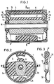
- the bearing element consists of a bearing sleeve 1, into which an elastomer body 2 is vulcanized.
- This elastomer body 2 consists of obliquely radially supporting rubber webs 2 a and 2 b, which carry an inner bearing bush 3 in the middle.
- the bearing bush 3 has an approximately trapezoidal outer cross section, but it can also consist of a smooth tube.
- An upper cavity 4 and a lower cavity 5 are delimited within the bearing sleeve 1 by the rubber webs 2 a and 2 b.
- a stop 6 can be vulcanized to the bearing sleeve 1 with a corresponding counterpart 7 on the bearing bush 3 and in the lower cavity 5 a further stop 8 made of elastomeric material.
- This bearing element is shown in a preloaded, installed state; in the non-prestressed state, the attachment 7 would be in contact with the stop 6.
- This initially conventional bearing element which can also have a different configuration - but based on the same basic principle - is now provided with a cap 10 and 11 on each of its faces for configuration as a hydraulically damped bearing, which have a cap according to the longitudinal section according to FIG. 3 have outer ring 12 and an inner ring 13 concentric therewith, between which an annular wall part 14 made of elastomeric material is vulcanized.
- These two caps 10 and 11 are placed laterally on the bearing element and clamped in a liquid-tight manner to the actual bearing element via an outer ring 15 and a tubular inner bushing 16.
- the cavities 4 and 5 now form externally closed chambers which are filled with a hydraulic fluid and are connected to one another via an annular channel 17 and 18 between the caps 10 and 11 and the actual bearing element.
- the liquid With a corresponding load on the bearing element or due to the vibrations introduced into it, the liquid is displaced from the upper chamber 4 into the lower chamber 5 and vice versa via the channels 17 and 18, with additional damping being brought about by the flow resistance of the overflow channels 17 and 18 becomes.
- the walls 19 and 20 bulge differently or only hen when loading or unloading the bearing or in accordance with the occurring vibration amplitudes, the cross section of the overflow channels 17 and 18 is increased or decreased depending on the amplitude.
- the damping of the bearing can thus be made smaller for certain amplitudes and larger for others.
- a variety of options are provided by special designs of the caps 10 and 11.
- the elastomeric wall parts 19 and 20 can have different cross sections over their circumference, as can be seen from the longitudinal sections according to FIGS. 1 and 3 and FIG. 4.
- these wall parts will also be able to bulge more easily when pressure builds up in the chamber 5.
- This design enables a broadband reduction in the dynamic stiffness of the bearing in the acoustic frequency range. B. with a thinner wall a reduction in the dynamic rigidity to lower frequencies occurs.
- overflow channels 18 can only be formed on one end face, or only one flow channel 17 remains open on one end face, while the cap material lies fully against the inner elastomer body by appropriate design of the wall, for example at point 21.
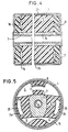
- an axially extending chamber 25 is additionally embedded in the rubber web 2a and a likewise axially extending chamber 26 in the rubber web 2b.
- These chambers 25 and 26 can be designed in the form of circular ring sections or else kidney-shaped.
- a hydraulic connection of the vertically superimposed chambers 4 and 5 and the two horizontally lying chambers 25 and 26 is thus formed via the annular channels 17 and 18 by the caps 10 and 11 placed on the end face.
- liquid can be displaced from chamber 25 into chamber 26 and vice versa via these channels 17 and 18.
Description
Die Erfindung bezieht sich auf ein vorspannbares und hydraulisch gedämpftes Lagerelement mit einer äußeren Lagerhülse und einem, von einem Elastomerkörper im Innern gehaltenen Innenteil, wobei der vom Innenteil angenähert radial nach beiden Seiten verlaufende Elastomerkörper oberhalb und unterhalb des Innenteils Kammern als mechanischen Federungsraum aufweist, die mit einer hydraulischen Flüssigkeit gefüllt sind und über einen Kanal miteinander in Verbindung stehen, und das Lagerelement stirnseitige Kappen aus elastisch verformbaren, elastomeren Material aufweist.The invention relates to a pretensionable and hydraulically damped bearing element with an outer bearing sleeve and an inner part held by an elastomer body inside, the elastomer body running approximately radially to both sides from the inner part having chambers above and below the inner part as a mechanical suspension space, which with are filled with a hydraulic fluid and are connected to one another via a channel, and the bearing element has end caps made of elastically deformable, elastomeric material.
Ein derartiges Lagerelement ist aus der JP-A-56 143 830 bekannt. Dabei stehen die beiden flüssigkeitsgefüllten Kammern über einen am Umfang des einen radialen Elastomerkörpers verlaufenden Kanal miteinander in Verbindung, wobei dieser Kanal seitlich durch einen Dichtring aus Gummi abgeschlossen ist.Such a bearing element is known from JP-A-56 143 830. The two liquid-filled chambers are connected to one another via a channel running on the circumference of a radial elastomer body, this channel being closed off at the side by a rubber sealing ring.
Durch diesen Überströmkanal zwischen den beiden flüssigkeitsgefüllten Kammern ist eine Dämpfung auftretender Schwingungen durch die Reibung der überströmenden Flüssigkeit an der Kanalwandung möglich. Wegen des konstanten Querschnittes dieses Überströmkanals, der sich auch bei starken Schwingungen und dadurch bedingten Verformungen des Elastomerkörpers nur unwesentlich ändert, ist auch eine Änderung des Dämpfungsverhaltens auch nur in sehr geringen Grenzen möglich, so daß die Dämpfung weitgehend unabhängig von jeweils auftretenden Amplituden ist.This overflow channel between the two liquid-filled chambers makes it possible to dampen vibrations that occur due to the friction of the overflowing liquid on the channel wall. Because of the constant cross-section of this overflow channel, which changes only insignificantly even with strong vibrations and the resulting deformations of the elastomer body, a change in the damping behavior is also possible only within very small limits, so that the damping is largely independent of the amplitudes that occur.
Demgegenüber liegt der vorliegenden Erfindung die Aufgabe zugrunde, ein zusätzlich hydraulisch gedämpftes Lagerelement zu schaffen, dessen Dämpfung abhängig von der jeweils auftretenden Amplitude unterschiedlich hoch eingestellt werden kann. Außerdem soll eine breitbandige Absenkung der dynamischen Steifigkeit im akustischen Frequenzbereich ermöglicht werden.In contrast, the object of the present invention is to create an additionally hydraulically damped bearing element, the damping of which can be set at different levels depending on the amplitude occurring in each case. In addition, a broadband reduction in the dynamic stiffness in the acoustic frequency range should be made possible.
Zur Lösung dieser Aufgabe ist ausgehend vom eingangs genannten Stand der Technik erfindungsgemäß vorgesehen, daß die Kappen ausschließlich zwischen sich und dem Elastomerkörper mindestens auf einer Stirnseite den Kanal bilden, wobei der Querschnitt des Kanals durch lastabhängige Verformung der Kappen veränderlich ist.To achieve this object, starting from the prior art mentioned at the outset, the invention provides that the caps form the channel exclusively between themselves and the elastomer body at least on one end face, the cross section of the channel being variable by load-dependent deformation of the caps.
Durch diese Ausbildung der stirnseitig aufgesetzten Kappen aus einem elastisch verformbaren Material werden sich die Wandungsteile der Kappen je nach Einfederung des Lagerelementes bzw. je nach Größe der auftretenden Amplituden unterschiedlich auswölben, so daß sich dadurch ein jeweils unterschiedlicher Kanalquerschnitt zu dem innenliegenden Elastomerkörper ergibt.This configuration of the caps placed on the end face made of an elastically deformable material causes the wall parts of the caps to bulge differently depending on the deflection of the bearing element or the size of the amplitudes that occur, so that this results in a different channel cross-section to the internal elastomer body.
Um auch eine lastabhängige Dämpfung in horizontaler Richtung zu erreichen, können zusätzlich beiderseits des Innenteils der Elastomerkörper ebenfalls axial verlaufende Kammern angeordnet sein, die mindestens zu einem der stirnseitigen Kanäle hin offen sind.In order to also achieve load-dependent damping in the horizontal direction, axially extending chambers can also be arranged on both sides of the inner part of the elastomer body, which are open towards at least one of the end channels.
Zweckmäßigerweise weisen die Kappen einen äußeren und einen inneren Ring aus starrem Material auf, zwischen denen ein ringförmiges Wandungsteil aus elastomerem Material einvulkanisiert ist.The caps expediently have an outer and an inner ring made of rigid material, between which an annular wall part made of elastomeric material is vulcanized.
Zur Erreichung einer unterschiedlichen Dämpfung ist es dabei ferner von Vorteil, wenn der elastomere Wandungsteil über seinen Umfang unterschiedlichen Querschnitt aufweist. Dabei ist es besonders zweckmäßig, wenn der Wandungsteil im Bereich der unteren Kammer eine geringere Wandstärke als im übrigen Umfangsbereich aufweist.To achieve a different damping, it is also advantageous if the elastomeric wall part has a different cross section over its circumference. It is particularly expedient if the wall part in the area of the lower chamber has a smaller wall thickness than in the rest of the peripheral area.
Anhand einer schematischen Zeichnung sind Aufbau und Wirkungsweise eines Ausführungsbeispiels nach der Erfindung näher erläutert.The structure and mode of operation of an exemplary embodiment according to the invention are explained in more detail with reference to a schematic drawing.
Dabei zeigen:
- Fig. 1 einen Längsschnitt in vertikaler Richtung durch das Lagerelement,
- Fig. 2 einen Querschnitt durch das Lagerelement entsprechend der Schnittlinie 11-11 nach Fig. 1,
- Fig. 3 einen Längsschnitt durch eine der stirnseitigen Kappen entsprechend dem Schnitt nach Fig. 1,
- Fig. 4 einen Längsschnitt durch ein Lagerelement in horizontaler Richtung entsprechend der Schnittlinie IV-IV nach Fig. 2 und
- Fig. 5 einen Querschnitt durch das Lagerelement mit zusätzlichen, bei horizontal wirkenden Kräften beaufschlagten Kammern.
- 1 shows a longitudinal section in the vertical direction through the bearing element,
- 2 shows a cross section through the bearing element along the section line 11-11 of FIG. 1,
- 3 shows a longitudinal section through one of the end caps corresponding to the section according to FIG. 1,
- Fig. 4 shows a longitudinal section through a bearing element in the horizontal direction according to the section line IV-IV of Fig. 2 and
- Fig. 5 shows a cross section through the bearing element with additional, acted upon by horizontally acting forces.
Wie zunächst aus Fig. 1, 2 und 4 ersichtlich ist, besteht das Lagerelement aus einer Lagerhülse 1, in die ein Elastomerkörper 2 einvulkanisiert ist. Dieser Elastomerkörper 2 besteht aus schräg radial tragenden Gummistegen 2 a und 2 b, die in ihrer Mitte eine innere Lagerbuchse 3 tragen. In dem dargestellten Ausführungsbeispiel weist die Lagerbuchse 3 einen etwa trapezförmigen äußeren Querschnitt auf, sie kann jedoch ebenso aus einem glatten Rohr bestehen. Durch die Gummistege 2 a und 2 b werden innerhalb der Lagerhülse 1 ein oberer Hohlraum 4 und ein unterer Hohlraum 5 begrenzt. Im oberen Hohlraum 4 kann dabei an die Lagerhülse 1 ein Anschlag 6 mit einem entsprechenden Gegenstück 7 auf der Lagerbuchse 3 und im unteren Hohlraum 5 ein weiterer Anschlag 8 aus elastomerem Material anvulkanisiert sein.As can first be seen from FIGS. 1, 2 and 4, the bearing element consists of a bearing sleeve 1, into which an elastomer body 2 is vulcanized. This elastomer body 2 consists of obliquely radially supporting
Dieses Lagerelement ist dabei in vorgespanntem, eingebautem Zustand gezeigt ; im nichtvorgespannten Zustand würde der Aufsatz 7 mit dem Anschlag 6 in Berührung stehen.This bearing element is shown in a preloaded, installed state; in the non-prestressed state, the attachment 7 would be in contact with the
Dieses zunächst herkömmliche Lagerelement, das auch eine andere Konfiguration - jedoch basierend auf dem gleichen Grundprinzip - aufweisen kann, ist nun zur Ausgestaltung als hydraulisch gedämpftes Lager an seinen Stirnseiten mit je einer Kappe 10 und 11 versehen, die entsprechend dem Längsschnitt nach Fig. 3 einen äußeren Ring 12 und einen dazu konzentrischen inneren Ring 13 aufweisen, zwischen denen ein ringförmiges Wandungsteil 14 aus elastomerem Material einvulkanisiert ist. Diese beiden Kappen 10 und 11 werden seitlich auf das Lagerelement aufgesetzt und über einen außenliegenden Ring 15 und eine rohrförmige Innenbuchse 16 mit dem eigentlichen Lagerelement flüssigkeitsdicht verspannt.This initially conventional bearing element, which can also have a different configuration - but based on the same basic principle - is now provided with a
Die Hohlräume 4 und 5 bilden jetzt nach außen abgeschlossene Kammern, die mit einer Hydraulikflüssigkeit gefüllt sind und über je einen ringförmigen Kanal 17 und 18 zwischen den Kappen 10 und 11 und dem eigentlichen Lagerelement miteinander in Verbindung stehen.The
Bei entsprechender Belastung des Lagerelementes bzw. durch die in diese eingeleiteten Schwingungen wird die Flüssigkeit von der oberen Kammer 4 in die untere Kammer 5 und umgekehrt über die Kanäle 17 bzw. 18 verdrängt, wobei durch den Strömungswiderstand der Überströmkanäle 17 und 18 eine zusätzliche Dämpfung bewirkt wird. Dadurch, daß bei einer Be- oder Entlastung des Lagers oder entsprechend den auftretenden Schwingungsamplituden sich die Wandungen 19 und 20 unterschiedlich auswölben oder einzig hen, wird der Querschnitt der Überströmkanäle 17 und 18 amplitudenabhängig vergrößert oder verkleinert. Somit kann die Dämpfung des Lagers für bestimmte Amplituden kleiner und für andere größer gestaltet werden. Dabei sind durch spezielle Ausbildungen der Kappen 10 und 11 die unterschiedlichste Möglichkeiten gegeben. So können die elastomeren Wandungsteile 19 bzw. 20 über ihren Umfang unterschiedlichen Querschnitt aufweisen, wie sich das aus den Längsschnitten nach Fig. 1 und 3 sowie Fig. 4 ergibt. Bei der dargestellten Ausführungsform, bei der die die Kammer 5 begrenzenden Wandungsteile 19 und 20 dünner ausgeführt sind als im oberen Bereich, werden diese Wandungsteile bei einem Druckaufbau in der Kammer 5 sich auch leichter auswölben können. Durch diese Gestaltung wird eine breitbandige Absenkung der dynamischen Steifigkeit des Lagers-im akustischen Frequenzbereich möglich, wobei z. B. bei einer dünneren Wandung eine Absenkung der dynamischen Steifigkeit zu niedrigeren Frequenzen auftritt.With a corresponding load on the bearing element or due to the vibrations introduced into it, the liquid is displaced from the
Eine weitere Möglichkeit zur Beeinflussung der Dämpfung besteht darin, daß man nur bestimmte Überströmkanäle offenläßt, wie sich das aus dem Längsschnitt nach Fig. 4 ergibt. So können beispielsweise Überströmkanäle 18 nur auf einer Stirnseite gebildet sein, oder aber auf einer Stirnseite bleibt nur ein Strömungskanal 17 offen, während durch entsprechende Gestaltung der Wandung, beispielsweise an der Stelle 21, das Kappenmaterial voll an den inneren Elastomerkörper anliegt.A further possibility for influencing the damping consists in leaving only certain overflow channels open, as can be seen from the longitudinal section according to FIG. 4. For example,
Nach dem in Fig. 5 dargestellten Ausführungsbeispiel sind zusätzlich in den Gummisteg 2a eine axial verlaufende Kammer 25 und in den Gummisteg 2b eine ebenfalls axial verlaufende Kammer 26 eingelassen. Diese Kammern 25 und 26 können in Form von Kreisringabschnitten oder aber auch nierenförmig ausgebildet sein.According to the exemplary embodiment shown in FIG. 5, an axially extending
Durch die stirnseitig aufgesetzten Kappen 10 und 11 wird über die ringförmigen Kanäle 17 und 18 somit eine hydraulische Verbindung der vertikal übereinander liegenden Kammern 4 und 5 sowie der beiden horizontal zueinander liegenden Kammern 25 und 26 gebildet.A hydraulic connection of the vertically superimposed
Damit kann bei einer horizontalen Belastung und entsprechenden Schwingungen über diese Kanäle 17 und 18 Flüssigkeit von der Kammer 25 in die Kammer 26 und umgedreht verdrängt werden.Thus, with a horizontal load and corresponding vibrations, liquid can be displaced from
Mit der zuletzt beschriebenen Ausbildung des Lagerelementes ist es also möglich, sowohl vertikale als auch horizontale Schwingungen gezielt zu dämpfen.With the configuration of the bearing element described last, it is thus possible to specifically dampen both vertical and horizontal vibrations.
Insgesamt ergibt sich also ein hydraulisch gedämpftes, buchsenförmiges Lagerelement mit einem amplitudenabhängigen Kanalquerschnitt und frequenzentkoppelnden Seitenwänden, das durch einfache Gestaltungselemente eine große Variationsbreite bezüglich zu erreichender Dämpfung und einer breitbandigen Absenkung der dynamischen Steifigkeit aufweist.All in all, this results in a hydraulically damped, bush-shaped bearing element with an amplitude-dependent channel cross section and frequency-decoupling side walls, which, due to simple design elements, has a wide range in terms of damping to be achieved and a broadband reduction in dynamic rigidity.
Claims (5)
Applications Claiming Priority (4)
| Application Number | Priority Date | Filing Date | Title |
|---|---|---|---|
| DE19853514268 DE3514268A1 (en) | 1985-04-19 | 1985-04-19 | PRELVETABLE AND HYDRAULIC DAMPED BEARING ELEMENT |
| DE3514268 | 1985-04-19 | ||
| DE19863605305 DE3605305A1 (en) | 1986-02-19 | 1986-02-19 | PRELVETABLE AND HYDRAULICALLY DAMPED BEARING ELEMENT |
| DE3605305 | 1986-02-19 |
Publications (4)
| Publication Number | Publication Date |
|---|---|
| EP0199240A2 EP0199240A2 (en) | 1986-10-29 |
| EP0199240A3 EP0199240A3 (en) | 1987-01-07 |
| EP0199240B1 EP0199240B1 (en) | 1988-10-19 |
| EP0199240B2 true EP0199240B2 (en) | 1994-10-12 |
Family
ID=25831541
Family Applications (1)
| Application Number | Title | Priority Date | Filing Date |
|---|---|---|---|
| EP86105098A Expired - Lifetime EP0199240B2 (en) | 1985-04-19 | 1986-04-14 | Prestressable mounting unit with hydraulic damping |
Country Status (4)
| Country | Link |
|---|---|
| EP (1) | EP0199240B2 (en) |
| BR (1) | BR8601748A (en) |
| DE (1) | DE3660972D1 (en) |
| ES (1) | ES293603Y (en) |
Families Citing this family (19)
| Publication number | Priority date | Publication date | Assignee | Title |
|---|---|---|---|---|
| DE3724432A1 (en) * | 1987-07-23 | 1989-02-02 | Freudenberg Carl Fa | SLEEVE RUBBER SPRING |
| DE8714241U1 (en) * | 1987-10-26 | 1987-12-10 | Fa. Carl Freudenberg, 6940 Weinheim, De | |
| DE3824272A1 (en) * | 1988-07-16 | 1990-03-29 | Joern Gmbh | JOINT BEARINGS, ESPECIALLY FOR A JOURNAL OF A MOTOR VEHICLE |
| FR2636391B1 (en) * | 1988-09-13 | 1993-02-19 | Hutchinson | IMPROVEMENTS TO HYDRAULIC ANTI-VIBRATION SLEEVES |
| DE3840176A1 (en) * | 1988-11-29 | 1990-05-31 | Freudenberg Carl Fa | SLEEVE RUBBER SPRING |
| JP2538464B2 (en) * | 1990-12-13 | 1996-09-25 | 東海ゴム工業株式会社 | Fluid filled cylinder mount |
| DE4140854C2 (en) * | 1990-12-13 | 1995-12-07 | Tokai Rubber Ind Ltd | Cylindrical, elastic bearing with a fluid filling |
| US5344126A (en) * | 1991-03-15 | 1994-09-06 | Bridgestone Corporation | Vibration isolation apparatus |
| DE19618688C2 (en) * | 1996-05-09 | 1999-03-25 | Freudenberg Carl Fa | Hydraulic bushing |
| JP3753471B2 (en) * | 1996-07-01 | 2006-03-08 | 倉敷化工株式会社 | Liquid-filled cylindrical mount |
| FR2766771B1 (en) * | 1997-07-30 | 1999-10-15 | Hutchinson | TORQUE RECOVERY LINK FOR INTERNAL COMBUSTION ENGINE |
| FR2794503B1 (en) * | 1999-06-03 | 2001-09-21 | Hutchinson | ANTIVIBRATORY CONNECTING ROD |
| DE10024536B4 (en) | 2000-05-18 | 2006-06-01 | Trelleborg Automotive Technical Centre Gmbh | Hydraulically damping bush |
| FR2853369B1 (en) * | 2003-04-03 | 2006-04-28 | Cf Gomma Spa | TORQUE RETRACTING ROD AND METHOD FOR MANUFACTURING THE SAME |
| DE102007028041B4 (en) * | 2007-06-14 | 2016-10-06 | Carl Freudenberg Kg | Elastomeric bearings especially for chassis bushes |
| DE102008040548B4 (en) * | 2008-07-18 | 2013-01-17 | Zf Friedrichshafen Ag | Hydraulically damping bush bearing |
| FR2948740B1 (en) * | 2009-08-03 | 2011-07-29 | Hutchinson | ANTI - VIBRATION BONDING DEVICE FOR VEHICLE AND VEHICLE COMPRISING SUCH A DEVICE. |
| DE102016215735A1 (en) | 2016-08-23 | 2018-03-01 | Contitech Vibration Control Gmbh | Rifle |
| DE102022113154A1 (en) | 2022-05-24 | 2023-11-30 | Vibracoustic Se | Elastomer bearing with protective cap |
Family Cites Families (4)
| Publication number | Priority date | Publication date | Assignee | Title |
|---|---|---|---|---|
| DE2755117C2 (en) * | 1977-12-10 | 1985-01-31 | Metzeler Kautschuk GmbH, 8000 München | Prestressable bearing element |
| JPS56143830A (en) * | 1980-04-10 | 1981-11-09 | Bridgestone Corp | Vibration proofing bush and manufacture thereof |
| DE3130830A1 (en) * | 1981-08-04 | 1983-02-24 | WOCO Franz-Josef Wolf & Co, 6483 Bad Soden-Salmünster | SPRING ELEMENT AND ITS USE |
| DE3441806A1 (en) * | 1984-11-15 | 1986-05-15 | Phoenix Ag, 2100 Hamburg | Elastic bush |
-
1986
- 1986-04-14 EP EP86105098A patent/EP0199240B2/en not_active Expired - Lifetime
- 1986-04-14 DE DE8686105098T patent/DE3660972D1/en not_active Expired
- 1986-04-15 ES ES1986293603U patent/ES293603Y/en not_active Expired
- 1986-04-18 BR BR8601748A patent/BR8601748A/en not_active IP Right Cessation
Also Published As
| Publication number | Publication date |
|---|---|
| DE3660972D1 (en) | 1988-11-24 |
| BR8601748A (en) | 1986-12-23 |
| EP0199240A3 (en) | 1987-01-07 |
| ES293603Y (en) | 1987-05-01 |
| EP0199240B1 (en) | 1988-10-19 |
| ES293603U (en) | 1986-08-16 |
| EP0199240A2 (en) | 1986-10-29 |
Similar Documents
| Publication | Publication Date | Title |
|---|---|---|
| EP0199240B2 (en) | Prestressable mounting unit with hydraulic damping | |
| DE3514268A1 (en) | PRELVETABLE AND HYDRAULIC DAMPED BEARING ELEMENT | |
| DE3125907C2 (en) | ||
| DE2841505C2 (en) | Hydraulically damping rubber mount | |
| DE3927715C2 (en) | Elastic suspension with a fluid filling | |
| EP0907844B1 (en) | Hydraulically damping elastomer bearing | |
| DE3342300C2 (en) | ||
| DE3605305A1 (en) | PRELVETABLE AND HYDRAULICALLY DAMPED BEARING ELEMENT | |
| DE10040201B4 (en) | Hydraulically damping bearing | |
| EP0332901B1 (en) | Elastic and hydraulically damped sleeve | |
| WO2019137645A1 (en) | Hydraulic bearing bush | |
| EP1707842B1 (en) | Hydraulically damped bush with axial sealing | |
| DE4137977A1 (en) | MULTI-CHAMBER HYDRO SOCKET | |
| DE4036538A1 (en) | Aggregate bearing for vehicles with two spring parts - acts independently of amplitude or frequency | |
| EP3158217A1 (en) | Hydraulic mount and motor vehicle having such a hydraulic mount | |
| DE102006032633A1 (en) | Bush bearing used in the vehicle industry comprises a sealing lip which is structured so that is oscillates corresponding to the damping volume displaced by deflecting a bearing body in the radial direction | |
| EP3737875A1 (en) | Hydraulic bearing bush | |
| DE19807949B4 (en) | Hydraulically damped storage facility | |
| EP1181465B1 (en) | Rubber bearing with graduated damping behavior | |
| DE60302837T2 (en) | Hydraulically damped elastic bearing | |
| DE2659844C3 (en) | Rubber mount with hydraulic damping | |
| EP1069338B1 (en) | Hydraulically dampened support | |
| DE102013105326A1 (en) | Hydraulic bush | |
| EP0389839B1 (en) | Elastic bearing element with hydraulic damping | |
| DE19932582C2 (en) | Hydraulically damping bearing |
Legal Events
| Date | Code | Title | Description |
|---|---|---|---|
| PUAI | Public reference made under article 153(3) epc to a published international application that has entered the european phase |
Free format text: ORIGINAL CODE: 0009012 |
|
| 17P | Request for examination filed |
Effective date: 19860414 |
|
| AK | Designated contracting states |
Kind code of ref document: A2 Designated state(s): DE FR GB IT SE |
|
| PUAL | Search report despatched |
Free format text: ORIGINAL CODE: 0009013 |
|
| AK | Designated contracting states |
Kind code of ref document: A3 Designated state(s): DE FR GB IT SE |
|
| 17Q | First examination report despatched |
Effective date: 19880314 |
|
| RAP1 | Party data changed (applicant data changed or rights of an application transferred) |
Owner name: METZELER GESELLSCHAFT MIT BESCHRAENKTER HAFTUNG |
|
| RAP3 | Party data changed (applicant data changed or rights of an application transferred) |
Owner name: METZELER GESELLSCHAFT MIT BESCHRAENKTER HAFTUNG |
|
| GRAA | (expected) grant |
Free format text: ORIGINAL CODE: 0009210 |
|
| AK | Designated contracting states |
Kind code of ref document: B1 Designated state(s): DE FR GB IT SE |
|
| ITF | It: translation for a ep patent filed |
Owner name: ING. C. GREGORJ S.P.A. |
|
| REF | Corresponds to: |
Ref document number: 3660972 Country of ref document: DE Date of ref document: 19881124 |
|
| ET | Fr: translation filed | ||
| GBT | Gb: translation of ep patent filed (gb section 77(6)(a)/1977) | ||
| PLBI | Opposition filed |
Free format text: ORIGINAL CODE: 0009260 |
|
| 26 | Opposition filed |
Opponent name: BOGE AG Effective date: 19890712 |
|
| ITTA | It: last paid annual fee | ||
| ITPR | It: changes in ownership of a european patent |
Owner name: CAMBIO RAGIONE SOCIALE;METZELER AUTOMOTIVE PROFILE |
|
| ITPR | It: changes in ownership of a european patent |
Owner name: CESSIONE;METZELER GIMETALL AG |
|
| REG | Reference to a national code |
Ref country code: GB Ref legal event code: 732E |
|
| PLAB | Opposition data, opponent's data or that of the opponent's representative modified |
Free format text: ORIGINAL CODE: 0009299OPPO |
|
| REG | Reference to a national code |
Ref country code: FR Ref legal event code: TP Ref country code: FR Ref legal event code: CD Ref country code: FR Ref legal event code: CA |
|
| R26 | Opposition filed (corrected) |
Opponent name: FICHTEL & SACHS AG Effective date: 19890712 |
|
| PGFP | Annual fee paid to national office [announced via postgrant information from national office to epo] |
Ref country code: SE Payment date: 19940415 Year of fee payment: 9 |
|
| PUAH | Patent maintained in amended form |
Free format text: ORIGINAL CODE: 0009272 |
|
| STAA | Information on the status of an ep patent application or granted ep patent |
Free format text: STATUS: PATENT MAINTAINED AS AMENDED |
|
| 27A | Patent maintained in amended form |
Effective date: 19941012 |
|
| AK | Designated contracting states |
Kind code of ref document: B2 Designated state(s): DE FR GB IT SE |
|
| ITF | It: translation for a ep patent filed |
Owner name: ING. C. GREGORJ S.P.A. |
|
| GBTA | Gb: translation of amended ep patent filed (gb section 77(6)(b)/1977) |
Effective date: 19941116 |
|
| EAL | Se: european patent in force in sweden |
Ref document number: 86105098.7 |
|
| ET3 | Fr: translation filed ** decision concerning opposition | ||
| PG25 | Lapsed in a contracting state [announced via postgrant information from national office to epo] |
Ref country code: SE Effective date: 19950415 |
|
| PGFP | Annual fee paid to national office [announced via postgrant information from national office to epo] |
Ref country code: GB Payment date: 19950504 Year of fee payment: 10 |
|
| PGFP | Annual fee paid to national office [announced via postgrant information from national office to epo] |
Ref country code: FR Payment date: 19950510 Year of fee payment: 10 |
|
| EUG | Se: european patent has lapsed |
Ref document number: 86105098.7 |
|
| PG25 | Lapsed in a contracting state [announced via postgrant information from national office to epo] |
Ref country code: GB Effective date: 19960414 |
|
| PGFP | Annual fee paid to national office [announced via postgrant information from national office to epo] |
Ref country code: DE Payment date: 19960418 Year of fee payment: 11 |
|
| GBPC | Gb: european patent ceased through non-payment of renewal fee |
Effective date: 19960414 |
|
| PG25 | Lapsed in a contracting state [announced via postgrant information from national office to epo] |
Ref country code: FR Effective date: 19961227 |
|
| REG | Reference to a national code |
Ref country code: FR Ref legal event code: ST |
|
| PG25 | Lapsed in a contracting state [announced via postgrant information from national office to epo] |
Ref country code: DE Free format text: LAPSE BECAUSE OF NON-PAYMENT OF DUE FEES Effective date: 19980101 |
|
| PG25 | Lapsed in a contracting state [announced via postgrant information from national office to epo] |
Ref country code: IT Free format text: LAPSE BECAUSE OF NON-PAYMENT OF DUE FEES;WARNING: LAPSES OF ITALIAN PATENTS WITH EFFECTIVE DATE BEFORE 2007 MAY HAVE OCCURRED AT ANY TIME BEFORE 2007. THE CORRECT EFFECTIVE DATE MAY BE DIFFERENT FROM THE ONE RECORDED. Effective date: 20050414 |
|
| APAH | Appeal reference modified |
Free format text: ORIGINAL CODE: EPIDOSCREFNO |