EP0526151A1 - Oil lubrication system for horizontal rotary scroll machine - Google Patents
Oil lubrication system for horizontal rotary scroll machine Download PDFInfo
- Publication number
- EP0526151A1 EP0526151A1 EP92306853A EP92306853A EP0526151A1 EP 0526151 A1 EP0526151 A1 EP 0526151A1 EP 92306853 A EP92306853 A EP 92306853A EP 92306853 A EP92306853 A EP 92306853A EP 0526151 A1 EP0526151 A1 EP 0526151A1
- Authority
- EP
- European Patent Office
- Prior art keywords
- drive shaft
- housing
- hollow space
- rotary machine
- circular plate
- Prior art date
- Legal status (The legal status is an assumption and is not a legal conclusion. Google has not performed a legal analysis and makes no representation as to the accuracy of the status listed.)
- Granted
Links
Images


Classifications
-
- F—MECHANICAL ENGINEERING; LIGHTING; HEATING; WEAPONS; BLASTING
- F04—POSITIVE - DISPLACEMENT MACHINES FOR LIQUIDS; PUMPS FOR LIQUIDS OR ELASTIC FLUIDS
- F04C—ROTARY-PISTON, OR OSCILLATING-PISTON, POSITIVE-DISPLACEMENT MACHINES FOR LIQUIDS; ROTARY-PISTON, OR OSCILLATING-PISTON, POSITIVE-DISPLACEMENT PUMPS
- F04C29/00—Component parts, details or accessories of pumps or pumping installations, not provided for in groups F04C18/00 - F04C28/00
- F04C29/02—Lubrication; Lubricant separation
- F04C29/025—Lubrication; Lubricant separation using a lubricant pump
-
- F—MECHANICAL ENGINEERING; LIGHTING; HEATING; WEAPONS; BLASTING
- F04—POSITIVE - DISPLACEMENT MACHINES FOR LIQUIDS; PUMPS FOR LIQUIDS OR ELASTIC FLUIDS
- F04C—ROTARY-PISTON, OR OSCILLATING-PISTON, POSITIVE-DISPLACEMENT MACHINES FOR LIQUIDS; ROTARY-PISTON, OR OSCILLATING-PISTON, POSITIVE-DISPLACEMENT PUMPS
- F04C18/00—Rotary-piston pumps specially adapted for elastic fluids
- F04C18/02—Rotary-piston pumps specially adapted for elastic fluids of arcuate-engagement type, i.e. with circular translatory movement of co-operating members, each member having the same number of teeth or tooth-equivalents
-
- F—MECHANICAL ENGINEERING; LIGHTING; HEATING; WEAPONS; BLASTING
- F04—POSITIVE - DISPLACEMENT MACHINES FOR LIQUIDS; PUMPS FOR LIQUIDS OR ELASTIC FLUIDS
- F04C—ROTARY-PISTON, OR OSCILLATING-PISTON, POSITIVE-DISPLACEMENT MACHINES FOR LIQUIDS; ROTARY-PISTON, OR OSCILLATING-PISTON, POSITIVE-DISPLACEMENT PUMPS
- F04C29/00—Component parts, details or accessories of pumps or pumping installations, not provided for in groups F04C18/00 - F04C28/00
- F04C29/02—Lubrication; Lubricant separation
- F04C29/028—Means for improving or restricting lubricant flow
-
- F—MECHANICAL ENGINEERING; LIGHTING; HEATING; WEAPONS; BLASTING
- F16—ENGINEERING ELEMENTS AND UNITS; GENERAL MEASURES FOR PRODUCING AND MAINTAINING EFFECTIVE FUNCTIONING OF MACHINES OR INSTALLATIONS; THERMAL INSULATION IN GENERAL
- F16N—LUBRICATING
- F16N7/00—Arrangements for supplying oil or unspecified lubricant from a stationary reservoir or the equivalent in or on the machine or member to be lubricated
- F16N7/38—Arrangements for supplying oil or unspecified lubricant from a stationary reservoir or the equivalent in or on the machine or member to be lubricated with a separate pump; Central lubrication systems
- F16N7/40—Arrangements for supplying oil or unspecified lubricant from a stationary reservoir or the equivalent in or on the machine or member to be lubricated with a separate pump; Central lubrication systems in a closed circulation system
-
- F—MECHANICAL ENGINEERING; LIGHTING; HEATING; WEAPONS; BLASTING
- F16—ENGINEERING ELEMENTS AND UNITS; GENERAL MEASURES FOR PRODUCING AND MAINTAINING EFFECTIVE FUNCTIONING OF MACHINES OR INSTALLATIONS; THERMAL INSULATION IN GENERAL
- F16N—LUBRICATING
- F16N13/00—Lubricating-pumps
- F16N13/20—Rotary pumps
-
- F—MECHANICAL ENGINEERING; LIGHTING; HEATING; WEAPONS; BLASTING
- F16—ENGINEERING ELEMENTS AND UNITS; GENERAL MEASURES FOR PRODUCING AND MAINTAINING EFFECTIVE FUNCTIONING OF MACHINES OR INSTALLATIONS; THERMAL INSULATION IN GENERAL
- F16N—LUBRICATING
- F16N7/00—Arrangements for supplying oil or unspecified lubricant from a stationary reservoir or the equivalent in or on the machine or member to be lubricated
- F16N7/36—Arrangements for supplying oil or unspecified lubricant from a stationary reservoir or the equivalent in or on the machine or member to be lubricated with feed by pumping action of the member to be lubricated or of a shaft of the machine; Centrifugal lubrication
Definitions
- the present invention relates to a rotary machine, more particularly, to a horizontally oriented rotary machine having an internal lubrication oil pump.
- a rotary machine such as a scroll type refrigerant compressor which is horizontally oriented is disclosed in U.S. Patent No. 4,917,582 issued to Fraser, Jr. et. al..
- the horizontally oriented scroll type refrigerant compressor includes an internal lubrication oil pump which functions to supply a lubrication oil in an oil sump of a compressor casing to the frictional surfaces of the internal component parts of the compressor.
- the oil pump operates by virtue of the reciprocating motion of one component part of an Oldham coupling mechanism which is used for preventing the rotation of an orbiting scroll member.
- the oil pump disclosed in the above U.S. '582 patent can not be applied to the scroll type refrigerant compressors having a non-Oldham coupling type rotation preventing mechanism, such as a ball coupling type rotation preventing mechanism because that the oil pump can only operates by virtue of the reciprocating motion of one component part of the Oldham coupling mechanism.
- one member rotatable with a drive shaft such as a balancing weight which is fixedly connected to the drive shaft may pass through the lubrication oil in oil sump located at an inner bottom portion of the compressor casing when a level of the lubrication oil in oil sump is excessively increased. This causes a defective torque fluctuation and useless operation of the drive shaft due to oil viscous drag.
- an object of the present invention to provide an internal lubrication oil pump which can be used for the various types of a horizontally oriented rotary machine.
- a rotary machine includes a housing, an inner block fixedly disposed within the housing so as to divide an inner hollow space of the housing into first and second portions, a drive shaft extending substantially in the horizontal direction, and driven mechanism driven by the drive shaft.
- the drive shaft is rotatably supported by the inner block and one part of the housing.
- the driven mechanism is disposed within the second portion of the inner hollow space of the housing and is operatively connected to one end of the drive shaft.
- the rotary machine further includes a pumping mechanism which pumps a lubrication liquid in a lower region of the first portion of the inner hollow space of the housing.
- the pumping mechanism is associated with the drive shaft so as to be operated by virtue of a rotational motion of the drive shaft.
- the rotary machine still further includes a shielding element which held between the inner block and one part of the housing in order to shield the drive shaft from the lubrication liquid in the lower region of the first portion of the inner hollow space of the casing.
- Figure 1 illustrates an overall construction of a horizontally oriented scroll type refrigerant compressor.
- the left side of the Figure will be referenced as the forward end or front and the right side of the Figure will be referenced as the rearward end.
- horizontally oriented scroll type refrigerant compressor 10 includes compressor casing 11 having first cup-shaped portion 12, second cup-shaped portion 13 and cylindrical portion 14 disposed between first and second cup-shaped portions 12 and 13.
- An opening end of first cup-shaped portion 12 is fixedly attached to an opening end of second cup-shaped portion 13 by a plurality of bolts 110 through cylindrical portion 14.
- Annular gasket 111 is sandwiched between the opening end of first cup-shaped portion 12 and the front end of cylindrical portion 14 so as to seal the mating surfaces of first cup-shaped portion 12 and cylindrical portion 14.
- annular gaskets 112 between which an outer peripheral portion of annular member 113 of an elastic material, for example, spring steel are sandwiched between the opening end of second cup-shaped portion 13 and the rear end of cylindrical portion 14 so as to seal the mating surfaces of cylindrical portion 14, annular elastic member 113 and second cup-shaped portion 13.
- an elastic material for example, spring steel
- First cup-shaped portion 12 includes hole 121 a centrally formed at a bottom region 121 thereof.
- Drive shaft 20 penetrates through hole 121 a, and is rotatably supported by plain bearing 21 fixedly disposed within hole 121a.
- Annular projection 122 forwardly extends from bottom region 121 of first cup-shaped portion 12, and surrounds an outer end portion of drive shaft 20.
- Electromagnetic clutch 200 through which the rotating motion of an external driving source (not shown) is intermittently transmitted to drive shaft 20 is mounted on annular projection 122.
- Shaft seal cavity 122a is defined in annular projection 122 for disposing shaft seal mechanism 123 therewithin.
- First cup-shaped portion 12 is provided with inlet port 121 formed at a side wall thereof. Inlet port 121b links an inner hollow space of compressor casing 11 to an external element of a refrigeration circuit, for example, an evaporator (not shown) through a pipe member (not shown).
- Inner block 141 is integral with and radially inwardly extends from a front end region of cylindrical portion 14.
- Cylindrical projection 142 is centrally formed at inner block 141, and includes opening 142a.
- An inner end of drive shaft 20 is rotatably supported by plain bearing 22 which is fixedly disposed within opening 142a.
- First cup-shaped portion 12 and inner block 141 define first inner hollow space 11 a.
- Second cup-shaped portion 13 and inner block 141 define second inner hollow space 11 b.
- Hole 143 is formed through an upper portion of inner block 141 so as to link first inner hollow apace 11 a to second inner hollow space 11 b.
- Fixed and orbiting scroll members 30 and 40 are disposed within second inner hollow space 11 b of compressor casing 11.
- Fixed scroll member 30 includes first circular end plate 31 and first spiral element or wrap 32 extending from a front end surface of first circular end plate 31.
- Orbiting scroll member 40 includes second circular end plate 41 and second spiral element or cap 42 extending from a rear end surface of second circular end plate 41.
- First and second spiral elements 32 and 42 interfit with each other with an angular and radial offset.
- Second cup-shaped portion 13 is provided with outlet port 131 a centrally formed at a bottom region 131 thereof.
- Axial annular projection 132 spacedly surrounding outlet port 131 a is formed at an inner surface of bottom region 131 of second cup-shaped portion 13.
- Circular depression 311 is centrally formed at a rear end surface of first circular end plate 31 of fixed scroll member 30 so as to face outlet port 131 a.
- Valved discharge port 31 a is formed through first circular end plate 31 so as to link circular depression 311 to a central sealed-off fluid pocket 50 defined by the central region of fixed and orbiting scroll members 30 and 40.
- Annular depression 312 spacedly surrounding circular depression 311 is formed at the rear end surface of first circular end plate 31 so as to receive axial annular projection 132 of second cup-shaped portion 13 therewithin.
- First annular rubber member 320 is compressedly disposed between the inner side surface of annular depression 312 and the inner peripheral surface of axial annular projection 132.
- Second annular rubber member 321 is compressedly disposed between the outer side surface of annular depression 312 and the outer peripheral surface of axial annular projection 132.
- First and second annular rubber members 320 and 321 seal the mating surfaces of annular depression 312 and axial annular projection 132 so that circular depression 311 is defined as a discharge chamber which is sealingly isolated from second inner hollow, space 11 b of compressor housing 11.
- Outlet port 131 a links discharge chamber 311 to an external element of a refrigeration circuit, for example, a condenser (not shown) through a pipe member (not shown).
- Annular wall 33 is formed at an outer peripheral portion of first circular end plate 31 so as to surround first and second spiral elements 32 and 42.
- Annular flange 331 radially extends from an outer surface of a front end portion of annular wall 33, and is fixedly attached to an inner peripheral portion of annular elastic member 113 by a plurality of bolts (not shown). According to the above-mentioned construction, fixed scroll member 30 is allowed to resiliently move in the axial direction within a small distance.
- Front circular depression 23 is centrally formed at the front end surfaces of cylindrical projection 142.
- the axis of front circular depression 23 is radially offset with the axis of opening 142a in horizontal direction.
- Front circular depression 23 includes large diameter section 23a and small diameter section 23b rear to large diameter section 23a.
- Rear circular depression 24 is centrally formed at the rear end surface of inner block 141.
- First balancing weight 60 is disposed within rear circular depression 24 and is fixedly connected to a front portion of pin member 25 which is integral with an axially extends from the inner end surface of drive shaft 20.
- the axis of pin member 25 is radially offset with the axis of drive shaft 20.
- Boss 43 is centrally formed at a front end surface of second circular end plate 41 opposite to second spiral element 42, and rotatably receives disc-shaped rotor 44 therewithin through plain bearing 26.
- Disc-shaped rotor 44 is connected to pin member 25. Accordingly, orbiting scroll member 40 is operatively connected to drive shaft 20 through pin member 25, disc-shaped rotor 44 and plain bearing 26.
- Oldham coupling mechanism 70 is interposed between inner block 141 and second circular end plate 41 of orbiting scroll meter 40. Oldham coupling mechanism 70 allows orbiting scroll 40 only to orbit during rotation of drive shaft 20.
- Second balancing weight 27 is fixedly connected to drive shaft 20 by bolt 271 at a location between bottom region 121 of first cup-shaped portion 12 and inner block 141.
- circular plate 81 is fitly disposed within small diameter section 23b of front circular depression 23, and includes hole 81 a centrally formed therethrough.
- An inner periphery of hole 81 a is generally sine curved, thereby forming a plurality of teeth 81 b.
- Cavity 142b having a irregular curve-shaped cross section is formed at cylindrical projection 142, and is liked to hole 81 a of circular plate 81.
- Annular plate 82 fixedly mounted on drive shaft 20 by key-groove mechanism 83 is loosely disposed within hole 81 a.
- An outer periphery of annular plate 82 is generally sine curved, thereby forming a plurality of teeth 82b.
- the number of teeth 81 b of circular plate 81 is greater than the number of teeth 82b of annular plate 82 by one.
- the number of teeth 81 b of circular plate 81 is eight and the number of teeth 82b of annular plate 82 is seven.
- Circular side plate 84 is fixedly disposed within large diameter section 23a of front circular depression 23 by a plurality of securing bolts (not shown), and includes hole 84a through which drive shaft 20 closely passes. Depression 841 having a irregular curve-shaped cross section is formed at a rear end surface of circular side plate 84. A lower part of depression 841 is linked to an upper part of hole 84a. Circular side plate 84 prevents the axial movement of circular plate 81 and annular plate 82. Circular plate 81 and annular plate 82, substantially form trochoid type pump mechanism 80. Circular plate 81 and annular plate 82 function as an outer and inner rotors of trochoid type pump mechanism 80, respectively.
- Axial hole 20a is axially formed through drive shaft 20.
- Axial hole 20a extends from the inner end surface of drive shaft 20 to a position rear to shaft seal mechanism 123 mounted about a front end portion of drive shaft 20.
- First, second, third and fourth radial holes 20b, 20c, 20d and 20e are radially formed through drive shaft 20.
- First radial hole 20b links a front end portion of axial hole 20a to shaft seal cavity 122a.
- Second radial hole 20c links axial hole 20a to depression 841 formed at the rear end surface of circular side plate 84.
- Third and fourth radial holes 20d and 20e links axial hole 20a to a gap created between plain bearing 22 and drive shaft 20.
- First conduit 121c is formed in bottom region 121 of first cup-shaped portion 12 and plain bearing 21 so as to link a gap created between plain bearing 21 and drive shaft 20 to first inner hollow space 11 a.
- Second conduit 142c is formed in the lower region of inner block 141 so as to link cavity 142b to oil sump 11 a which positions at a lower portion of first inner hollow space 11 c.
- Annular cylindrical member 90 as shown in Figure 2 is fixedly and hermetically held between bottom region 121 of first cup-shaped portion 12 and cylindrical projection 142 of inner block 141, and spacedly surrounds an intermediate portion of drive shaft 20 and second balancing weight 27.
- second balancing weight 27 rotates with drive shaft 20 without passing through the oil sump even when a level of the lubrication oil in oil sump 11 c is excessively increased. Accordingly, drive shaft 20 can rotates without a defective torque fluctuation and useless operation thereof.
- semi-annular cylindrical member 90' may be fixedly held between bottom region 121 of first cup-shaped portion 12 and cylindrical projection 142 of inner block 141 with allowing an inner hollow space thereof to open upwardly, if an amount of the lubrication oil in the refrigeration circuit is determined to be able to avoid the overflowing of the lubrication oil into the inner hollow space of semi-annular cylindrical member 90' in any operational condition of the refrigeration circuit.
- Rectangular plate 91 is fixedly connected to the upper front end surface of cylindrical projection 142 of inner block 141 by a plurality of bolts 91 a.
- the refrigerant gas flowing from the evaporator (not shown) is flows into first inner hollow space 11 a through inlet port 121 b, and further flows to second inner hollow space 11 through hole 143.
- Rectangular plate 91 locates on a flow path of the refrigerant gas from first inner hollow space 11 a to hole 143 so that the suspended lubrication oil mist in the refrigerant gas is effectively separated therefrom due to a collision with rectangular plate 91.
- the refrigerant gas flowing into second inner hollow space 11 is taken into the outermost located sealed-off fluid pockets between scroll members 30 and 40 via Oldham coupling mechanism 70, then moves toward the center of spiral elements 32 and 42 during the orbital motion of orbiting scroll 40 with a resultant volume reduction and compression, and is discharged to discharge chamber 311 through valved discharge port 31a.
- the discharged refrigerant gas in discharge chamber 311 then flows to the condenser (not shown) through outlet port 131 a.
- trochoid type pump mechanism 80 Operation of trochoid type pump mechanism 80 is as follows. With reference to Figures 4-7 in addition to Figure 1, when inner rotor 82 rotates with drive shaft 20 in clockwise as shown by arrow "A" in Figure 5, outer rotor 81 dependently rotates in also clockwise due to an engagement between a part of teeth 82b of inner rotor 82 with a part of teeth 81 b of outer rotor 81. With paying attention to the arrows in Figure 1, by virtue of the rotational motion of both inner and outer rotors 82 and 81, the lubrication oil is continuously pumped from oil sump 11 via second conduit 142c and cavity 142b, and is continuously discharged to depression 841 of circular side plate 84.
- the lubrication oil in depression 841 radially inwardly flows through second radial hole 20c with overcoming the centrifugal force generated by the rotational motion of drive shaft 20, and then flows into axial hole 20a.
- the lubrication oil flowing into axial hole 20a further flows through axial hole 20a in both the forward and rearward directions.
- the lubrication oil flowing through axial hole 20a in the forward direction further flows into shaft seal cavity 122a through first radial hole 20b so as to lubricate the frictional surfaces of drive shaft 20 and shaft seal mechanism 123.
- the lubrication oil in shaft seal cavity 122a flows into the gap created between drive shaft 20 and plain bearing 21 so as to lubricate the frictional surfaces of drive shaft 20 and plain bearing 21, and further flows to the lower portion of first inner hollow space 11 a through first conduit 121c so as to be joined to the lubrication oil in oil sump 11 c.
- the lubrication oil flowing through axial hole 20a in the rearward direction further flows into the gap created between the inner end portion of drive shaft 20 and plain bearing 22 through third and fourth radial holes 20d and 20e so as to lubricate the frictional surfaces of drive shaft 20 and plain bearing 22, and then flows out rear circular depression 24.
- axial hole 20a may be extended to a rear end surface of disc-shaped rotor 44 in order to more effectively lubricate the frictional surfaces of plain bearing 26 and disc-shaped rotor 44.
- the internal lubrication oil pump is formed by the elements which are associated with the drive shaft, and operates by virtue of the rotational motion of the drive shaft. According to the construction and operational manner, the internal lubrication oil pump can be used for the various types of the horizontally oriented rotary machine.
Abstract
Description
- The present invention relates to a rotary machine, more particularly, to a horizontally oriented rotary machine having an internal lubrication oil pump.
- A rotary machine, such as a scroll type refrigerant compressor which is horizontally oriented is disclosed in U.S. Patent No. 4,917,582 issued to Fraser, Jr. et. al.. In U.S. '582 patent, the horizontally oriented scroll type refrigerant compressor includes an internal lubrication oil pump which functions to supply a lubrication oil in an oil sump of a compressor casing to the frictional surfaces of the internal component parts of the compressor. The oil pump operates by virtue of the reciprocating motion of one component part of an Oldham coupling mechanism which is used for preventing the rotation of an orbiting scroll member.
- In comparison with a vertically oriented scroll type refrigerant compressor having an internal lubrication oil pump as disclosed in Japanese Patent Application Publication No. 63-36076, the above U.S. '582 patent can downsize the compressor. Especially, the height of the compressor can be remarkably reduced.
- However, the oil pump disclosed in the above U.S. '582 patent can not be applied to the scroll type refrigerant compressors having a non-Oldham coupling type rotation preventing mechanism, such as a ball coupling type rotation preventing mechanism because that the oil pump can only operates by virtue of the reciprocating motion of one component part of the Oldham coupling mechanism.
- Furthermore, in U.S. '582 patent, one member rotatable with a drive shaft, such as a balancing weight which is fixedly connected to the drive shaft may pass through the lubrication oil in oil sump located at an inner bottom portion of the compressor casing when a level of the lubrication oil in oil sump is excessively increased. This causes a defective torque fluctuation and useless operation of the drive shaft due to oil viscous drag.
- Accordingly, it is an object of the present invention to provide an internal lubrication oil pump which can be used for the various types of a horizontally oriented rotary machine.
- It is another object of the present invention to provide a horizontally oriented rotary machine in which a drive shaft can rotate without receiving oil viscous drag.
- According to the present invention, a rotary machine includes a housing, an inner block fixedly disposed within the housing so as to divide an inner hollow space of the housing into first and second portions, a drive shaft extending substantially in the horizontal direction, and driven mechanism driven by the drive shaft. The drive shaft is rotatably supported by the inner block and one part of the housing. The driven mechanism is disposed within the second portion of the inner hollow space of the housing and is operatively connected to one end of the drive shaft.
- The rotary machine further includes a pumping mechanism which pumps a lubrication liquid in a lower region of the first portion of the inner hollow space of the housing. The pumping mechanism is associated with the drive shaft so as to be operated by virtue of a rotational motion of the drive shaft.
- The rotary machine still further includes a shielding element which held between the inner block and one part of the housing in order to shield the drive shaft from the lubrication liquid in the lower region of the first portion of the inner hollow space of the casing.
- In the accompanying drawings:-
- Figure 1 is a longitudinal sectional view of a scroll type refrigerant compressor in accordance with one embodiment of the present invention.
- Figure 2 is a perspective view of an annular cylindrical pipe member spacedly surrounding a drive shaft of the scroll type refrigerant compressor shown in Figure 1.
- Figure 3 is a perspective view of a semi-annular cylindrical pipe member which may be replaced with the cylindrical pipe member shown in Figure 2.
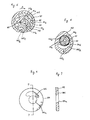
- Figure 4 is an enlarged cross-sectional view taken on line 4-4 of Figure 1.
- Figure 5 is an enlarged cross-sectional view taken on line 5-5 of Figure 1.
- Figure 6 is an enlarged side view of an annular plate which forms a part of a trochoid type pump mechanism shown in Figure 1.
- Figure 7 is a cross-sectional view taken on line 7-7 of Figure 6.
- Figure 1 illustrates an overall construction of a horizontally oriented scroll type refrigerant compressor. For purposes of explanation only, the left side of the Figure will be referenced as the forward end or front and the right side of the Figure will be referenced as the rearward end.
- With reference to Figure 1, horizontally oriented scroll
type refrigerant compressor 10 includes compressor casing 11 having first cup-shaped portion 12, second cup-shaped portion 13 and cylindrical portion 14 disposed between first and second cup-shaped portions shaped portion 12 is fixedly attached to an opening end of second cup-shaped portion 13 by a plurality ofbolts 110 through cylindrical portion 14.Annular gasket 111 is sandwiched between the opening end of first cup-shaped portion 12 and the front end of cylindrical portion 14 so as to seal the mating surfaces of first cup-shaped portion 12 and cylindrical portion 14. A pair ofannular gaskets 112 between which an outer peripheral portion ofannular member 113 of an elastic material, for example, spring steel are sandwiched between the opening end of second cup-shaped portion 13 and the rear end of cylindrical portion 14 so as to seal the mating surfaces of cylindrical portion 14, annularelastic member 113 and second cup-shaped portion 13. - First cup-
shaped portion 12 includeshole 121 a centrally formed at abottom region 121 thereof.Drive shaft 20 penetrates throughhole 121 a, and is rotatably supported by plain bearing 21 fixedly disposed withinhole 121a.Annular projection 122 forwardly extends frombottom region 121 of first cup-shaped portion 12, and surrounds an outer end portion ofdrive shaft 20.Electromagnetic clutch 200 through which the rotating motion of an external driving source (not shown) is intermittently transmitted to driveshaft 20 is mounted onannular projection 122.Shaft seal cavity 122a is defined inannular projection 122 for disposingshaft seal mechanism 123 therewithin. First cup-shaped portion 12 is provided withinlet port 121 formed at a side wall thereof.Inlet port 121b links an inner hollow space of compressor casing 11 to an external element of a refrigeration circuit, for example, an evaporator (not shown) through a pipe member (not shown). -
Inner block 141 is integral with and radially inwardly extends from a front end region of cylindrical portion 14.Cylindrical projection 142 is centrally formed atinner block 141, and includes opening 142a. An inner end ofdrive shaft 20 is rotatably supported by plain bearing 22 which is fixedly disposed within opening 142a. First cup-shaped portion 12 andinner block 141 define first inner hollow space 11 a. Second cup-shaped portion 13 andinner block 141 define second inner hollow space 11 b.Hole 143 is formed through an upper portion ofinner block 141 so as to link first inner hollow apace 11 a to second inner hollow space 11 b. - Fixed and orbiting
scroll members scroll member 30 includes firstcircular end plate 31 and first spiral element or wrap 32 extending from a front end surface of firstcircular end plate 31.Orbiting scroll member 40 includes secondcircular end plate 41 and second spiral element orcap 42 extending from a rear end surface of secondcircular end plate 41. First and secondspiral elements 32 and 42 interfit with each other with an angular and radial offset. - Second cup-
shaped portion 13 is provided with outlet port 131 a centrally formed at abottom region 131 thereof. Axialannular projection 132 spacedly surrounding outlet port 131 a is formed at an inner surface ofbottom region 131 of second cup-shaped portion 13. Circular depression 311 is centrally formed at a rear end surface of firstcircular end plate 31 of fixedscroll member 30 so as to face outlet port 131 a.Valved discharge port 31 a is formed through firstcircular end plate 31 so as to link circular depression 311 to a central sealed-offfluid pocket 50 defined by the central region of fixed and orbitingscroll members Annular depression 312 spacedly surrounding circular depression 311 is formed at the rear end surface of firstcircular end plate 31 so as to receive axialannular projection 132 of second cup-shaped portion 13 therewithin. - First
annular rubber member 320 is compressedly disposed between the inner side surface ofannular depression 312 and the inner peripheral surface of axialannular projection 132. Secondannular rubber member 321 is compressedly disposed between the outer side surface ofannular depression 312 and the outer peripheral surface of axialannular projection 132. First and secondannular rubber members annular depression 312 and axialannular projection 132 so that circular depression 311 is defined as a discharge chamber which is sealingly isolated from second inner hollow, space 11 b of compressor housing 11. Outlet port 131 a links discharge chamber 311 to an external element of a refrigeration circuit, for example, a condenser (not shown) through a pipe member (not shown). -
Annular wall 33 is formed at an outer peripheral portion of firstcircular end plate 31 so as to surround first and secondspiral elements 32 and 42.Annular flange 331 radially extends from an outer surface of a front end portion ofannular wall 33, and is fixedly attached to an inner peripheral portion of annularelastic member 113 by a plurality of bolts (not shown). According to the above-mentioned construction, fixedscroll member 30 is allowed to resiliently move in the axial direction within a small distance. - Front
circular depression 23 is centrally formed at the front end surfaces ofcylindrical projection 142. The axis of frontcircular depression 23 is radially offset with the axis of opening 142a in horizontal direction. Frontcircular depression 23 includes large diameter section 23a and small diameter section 23b rear to large diameter section 23a. Rear circular depression 24 is centrally formed at the rear end surface ofinner block 141. First balancingweight 60 is disposed within rear circular depression 24 and is fixedly connected to a front portion of pin member 25 which is integral with an axially extends from the inner end surface ofdrive shaft 20. The axis of pin member 25 is radially offset with the axis ofdrive shaft 20.Boss 43 is centrally formed at a front end surface of secondcircular end plate 41 opposite tosecond spiral element 42, and rotatably receives disc-shapedrotor 44 therewithin throughplain bearing 26. Disc-shapedrotor 44 is connected to pin member 25. Accordingly, orbitingscroll member 40 is operatively connected to driveshaft 20 through pin member 25, disc-shapedrotor 44 andplain bearing 26.Oldham coupling mechanism 70 is interposed betweeninner block 141 and secondcircular end plate 41 of orbitingscroll meter 40.Oldham coupling mechanism 70 allows orbitingscroll 40 only to orbit during rotation ofdrive shaft 20. - Second balancing
weight 27 is fixedly connected to driveshaft 20 by bolt 271 at a location betweenbottom region 121 of first cup-shapedportion 12 andinner block 141. - With reference to Figures 4-7 additionally,
circular plate 81 is fitly disposed within small diameter section 23b of frontcircular depression 23, and includes hole 81 a centrally formed therethrough. An inner periphery of hole 81 a is generally sine curved, thereby forming a plurality of teeth 81 b. Cavity 142b having a irregular curve-shaped cross section is formed atcylindrical projection 142, and is liked to hole 81 a ofcircular plate 81.Annular plate 82 fixedly mounted ondrive shaft 20 by key-groove mechanism 83 is loosely disposed within hole 81 a. An outer periphery ofannular plate 82 is generally sine curved, thereby forming a plurality of teeth 82b. The number of teeth 81 b ofcircular plate 81 is greater than the number of teeth 82b ofannular plate 82 by one. In this embodiment, the number of teeth 81 b ofcircular plate 81 is eight and the number of teeth 82b ofannular plate 82 is seven. -
Circular side plate 84 is fixedly disposed within large diameter section 23a of frontcircular depression 23 by a plurality of securing bolts (not shown), and includeshole 84a through which driveshaft 20 closely passes.Depression 841 having a irregular curve-shaped cross section is formed at a rear end surface ofcircular side plate 84. A lower part ofdepression 841 is linked to an upper part ofhole 84a.Circular side plate 84 prevents the axial movement ofcircular plate 81 andannular plate 82.Circular plate 81 andannular plate 82, substantially form trochoidtype pump mechanism 80.Circular plate 81 andannular plate 82 function as an outer and inner rotors of trochoidtype pump mechanism 80, respectively. -
Axial hole 20a is axially formed throughdrive shaft 20.Axial hole 20a extends from the inner end surface ofdrive shaft 20 to a position rear toshaft seal mechanism 123 mounted about a front end portion ofdrive shaft 20. First, second, third and fourthradial holes drive shaft 20. Firstradial hole 20b links a front end portion ofaxial hole 20a toshaft seal cavity 122a. Second radial hole 20c linksaxial hole 20a todepression 841 formed at the rear end surface ofcircular side plate 84. Third and fourthradial holes 20d and 20e linksaxial hole 20a to a gap created betweenplain bearing 22 and driveshaft 20. -
First conduit 121c is formed inbottom region 121 of first cup-shapedportion 12 andplain bearing 21 so as to link a gap created betweenplain bearing 21 and driveshaft 20 to first inner hollow space 11 a. Second conduit 142c is formed in the lower region ofinner block 141 so as to link cavity 142b to oil sump 11 a which positions at a lower portion of first inner hollow space 11 c. - Annular
cylindrical member 90 as shown in Figure 2 is fixedly and hermetically held betweenbottom region 121 of first cup-shapedportion 12 andcylindrical projection 142 ofinner block 141, and spacedly surrounds an intermediate portion ofdrive shaft 20 and second balancingweight 27. As a result, an invasion of the lubrication oil to an inner hollow space of annularcylindrical member 90 is prevented even when a level of the lubrication oil in oil sump 11 c is excessively increased. Therefore, second balancingweight 27 rotates withdrive shaft 20 without passing through the oil sump even when a level of the lubrication oil in oil sump 11 c is excessively increased. Accordingly, driveshaft 20 can rotates without a defective torque fluctuation and useless operation thereof. - Furthermore, semi-annular cylindrical member 90' may be fixedly held between
bottom region 121 of first cup-shapedportion 12 andcylindrical projection 142 ofinner block 141 with allowing an inner hollow space thereof to open upwardly, if an amount of the lubrication oil in the refrigeration circuit is determined to be able to avoid the overflowing of the lubrication oil into the inner hollow space of semi-annular cylindrical member 90' in any operational condition of the refrigeration circuit. -
Rectangular plate 91 is fixedly connected to the upper front end surface ofcylindrical projection 142 ofinner block 141 by a plurality of bolts 91 a. - In operation of
compressor 10, the refrigerant gas flowing from the evaporator (not shown) is flows into first inner hollow space 11 a throughinlet port 121 b, and further flows to second inner hollow space 11 throughhole 143.Rectangular plate 91 locates on a flow path of the refrigerant gas from first inner hollow space 11 a to hole 143 so that the suspended lubrication oil mist in the refrigerant gas is effectively separated therefrom due to a collision withrectangular plate 91. The refrigerant gas flowing into second inner hollow space 11 is taken into the outermost located sealed-off fluid pockets betweenscroll members Oldham coupling mechanism 70, then moves toward the center ofspiral elements 32 and 42 during the orbital motion of orbitingscroll 40 with a resultant volume reduction and compression, and is discharged to discharge chamber 311 throughvalved discharge port 31a. The discharged refrigerant gas in discharge chamber 311 then flows to the condenser (not shown) through outlet port 131 a. - Operation of trochoid
type pump mechanism 80 is as follows. With reference to Figures 4-7 in addition to Figure 1, wheninner rotor 82 rotates withdrive shaft 20 in clockwise as shown by arrow "A" in Figure 5,outer rotor 81 dependently rotates in also clockwise due to an engagement between a part of teeth 82b ofinner rotor 82 with a part of teeth 81 b ofouter rotor 81. With paying attention to the arrows in Figure 1, by virtue of the rotational motion of both inner andouter rotors depression 841 ofcircular side plate 84. The lubrication oil indepression 841 radially inwardly flows through second radial hole 20c with overcoming the centrifugal force generated by the rotational motion ofdrive shaft 20, and then flows intoaxial hole 20a. The lubrication oil flowing intoaxial hole 20a further flows throughaxial hole 20a in both the forward and rearward directions. - The lubrication oil flowing through
axial hole 20a in the forward direction further flows intoshaft seal cavity 122a through firstradial hole 20b so as to lubricate the frictional surfaces ofdrive shaft 20 andshaft seal mechanism 123. The lubrication oil inshaft seal cavity 122a flows into the gap created betweendrive shaft 20 andplain bearing 21 so as to lubricate the frictional surfaces ofdrive shaft 20 andplain bearing 21, and further flows to the lower portion of first inner hollow space 11 a throughfirst conduit 121c so as to be joined to the lubrication oil in oil sump 11 c. - On the other hand, the lubrication oil flowing through
axial hole 20a in the rearward direction further flows into the gap created between the inner end portion ofdrive shaft 20 andplain bearing 22 through third and fourthradial holes 20d and 20e so as to lubricate the frictional surfaces ofdrive shaft 20 andplain bearing 22, and then flows out rear circular depression 24. - Furthermore,
axial hole 20a may be extended to a rear end surface of disc-shapedrotor 44 in order to more effectively lubricate the frictional surfaces ofplain bearing 26 and disc-shapedrotor 44. - As described above, the internal lubrication oil pump is formed by the elements which are associated with the drive shaft, and operates by virtue of the rotational motion of the drive shaft. According to the construction and operational manner, the internal lubrication oil pump can be used for the various types of the horizontally oriented rotary machine.
Claims (9)
Applications Claiming Priority (4)
| Application Number | Priority Date | Filing Date | Title |
|---|---|---|---|
| JP067318U JPH0512687U (en) | 1991-07-31 | 1991-07-31 | Rotating machine |
| JP67317/91 | 1991-07-31 | ||
| JP67318/91 | 1991-07-31 | ||
| JP067317U JPH0512683U (en) | 1991-07-31 | 1991-07-31 | Rotating machine |
Publications (2)
| Publication Number | Publication Date |
|---|---|
| EP0526151A1 true EP0526151A1 (en) | 1993-02-03 |
| EP0526151B1 EP0526151B1 (en) | 1995-10-18 |
Family
ID=26408507
Family Applications (1)
| Application Number | Title | Priority Date | Filing Date |
|---|---|---|---|
| EP92306853A Expired - Lifetime EP0526151B1 (en) | 1991-07-31 | 1992-07-28 | Oil lubrication system for horizontal rotary scroll machine |
Country Status (6)
| Country | Link |
|---|---|
| US (1) | US5330335A (en) |
| EP (1) | EP0526151B1 (en) |
| KR (1) | KR970003266B1 (en) |
| AU (2) | AU645433B2 (en) |
| CA (1) | CA2074882A1 (en) |
| DE (1) | DE69205517T2 (en) |
Families Citing this family (17)
| Publication number | Priority date | Publication date | Assignee | Title |
|---|---|---|---|---|
| JPH09151846A (en) * | 1995-11-30 | 1997-06-10 | Sanden Corp | Variable displacement cam plate type compressor |
| US5888057A (en) * | 1996-06-28 | 1999-03-30 | Sanden Corporation | Scroll-type refrigerant fluid compressor having a lubrication path through the orbiting scroll |
| US6071101A (en) * | 1997-09-22 | 2000-06-06 | Mind Tech Corp. | Scroll-type fluid displacement device having flow diverter, multiple tip seal and semi-radial compliant mechanism |
| US6129531A (en) * | 1997-12-22 | 2000-10-10 | Copeland Corporation | Open drive scroll machine |
| DE19922511B4 (en) * | 1998-05-18 | 2004-07-08 | Lg Electronics Inc. | Oil circulation structure for a linear compressor |
| DE19825650C2 (en) * | 1998-06-09 | 2001-03-01 | Danfoss As | Lube oil supply device for a device with a rotating device shaft |
| US6315536B1 (en) | 1999-11-18 | 2001-11-13 | Copeland Corporation | Suction inlet screen and funnel for a compressor |
| JP3447993B2 (en) * | 1999-11-19 | 2003-09-16 | 三笠産業株式会社 | Oil lubrication mechanism of vibrator |
| JP2002257063A (en) | 2001-02-28 | 2002-09-11 | Sanden Corp | Scroll type compressor |
| JP2003232285A (en) | 2002-02-12 | 2003-08-22 | Sanden Corp | Scroll type compressor |
| US6752605B2 (en) | 2002-10-15 | 2004-06-22 | Tecumseh Products Company | Horizontal two stage rotary compressor with a bearing-driven lubrication structure |
| US7841845B2 (en) * | 2005-05-16 | 2010-11-30 | Emerson Climate Technologies, Inc. | Open drive scroll machine |
| JP4369940B2 (en) * | 2006-07-12 | 2009-11-25 | アイシン・エーアイ株式会社 | Lubricating structure of rotary shaft oil seal |
| JP4225342B2 (en) * | 2006-10-04 | 2009-02-18 | トヨタ自動車株式会社 | In-wheel motor structure |
| US8747088B2 (en) * | 2007-11-27 | 2014-06-10 | Emerson Climate Technologies, Inc. | Open drive scroll compressor with lubrication system |
| FR3062430B1 (en) * | 2017-01-27 | 2021-05-21 | Danfoss Commercial Compressors | SPIRAL COMPRESSOR WITH ORBITAL DISCS LUBRICATION SYSTEM |
| FR3102793B1 (en) * | 2019-11-04 | 2021-10-29 | Danfoss Commercial Compressors | Scroll compressor having first and second axial stabilization arrangements |
Citations (2)
| Publication number | Priority date | Publication date | Assignee | Title |
|---|---|---|---|---|
| DE3627579A1 (en) * | 1985-08-23 | 1987-03-05 | Hitachi Ltd | SPIRAL COMPRESSOR |
| DE3825690A1 (en) * | 1987-08-10 | 1989-02-23 | Hitachi Ltd | OIL FEEDING DEVICE FOR A SPIRAL COMPRESSOR |
Family Cites Families (29)
| Publication number | Priority date | Publication date | Assignee | Title |
|---|---|---|---|---|
| US1191217A (en) * | 1915-11-20 | 1916-07-18 | Frick Co | Oil-splash shield for engine-crank casings. |
| US1437927A (en) * | 1919-03-05 | 1922-12-05 | Ind Res Corp | Engine oiler |
| AT141052B (en) * | 1931-05-15 | 1935-03-25 | Bosch Robert | Compression refrigeration machine. |
| US2992769A (en) * | 1957-03-20 | 1961-07-18 | Petty Lab Inc | Rotary fluid compressors |
| US3135460A (en) * | 1960-10-19 | 1964-06-02 | Gen Motors Corp | Refrigerating apparatus |
| US3317123A (en) * | 1965-09-02 | 1967-05-02 | Whirlpool Co | Compressor lubrication |
| US3877853A (en) * | 1971-07-08 | 1975-04-15 | Borg Warner | Vane controlling system for rotary sliding vane compressor |
| GB1378543A (en) * | 1971-07-08 | 1974-12-27 | Borg Warner | Rotary compressor of sliding vane type |
| JPS4947208U (en) * | 1972-07-27 | 1974-04-25 | ||
| SE415996B (en) * | 1972-09-25 | 1980-11-17 | Stal Refrigeration Ab | LAMEL TYPE ROTATION COMPRESSOR |
| US3865515A (en) * | 1973-12-05 | 1975-02-11 | Trw Inc | Self adjusting tangency-clearance compressor with liquid purge capability |
| US4005948A (en) * | 1974-10-09 | 1977-02-01 | Sankyo Electric Co., Ltd. | Lubrication system for compressor unit |
| US3986799A (en) * | 1975-11-03 | 1976-10-19 | Arthur D. Little, Inc. | Fluid-cooled, scroll-type, positive fluid displacement apparatus |
| US4314796A (en) * | 1978-09-04 | 1982-02-09 | Sankyo Electric Company Limited | Scroll-type compressor with thrust bearing lubricating and bypass means |
| US4332535A (en) * | 1978-12-16 | 1982-06-01 | Sankyo Electric Company Limited | Scroll type compressor having an oil separator and oil sump in the suction chamber |
| JPS55107093A (en) * | 1979-02-13 | 1980-08-16 | Hitachi Ltd | Enclosed type scroll compressor |
| JPS55109793A (en) * | 1979-02-17 | 1980-08-23 | Sanden Corp | Displacement type fluid compressor |
| JPS58133495A (en) * | 1982-02-02 | 1983-08-09 | Matsushita Electric Ind Co Ltd | Oil feeder for rotary vane compressor |
| JPS5960092A (en) * | 1982-09-30 | 1984-04-05 | Toshiba Corp | Scroll compressor |
| JPS59224493A (en) * | 1983-06-03 | 1984-12-17 | Mitsubishi Electric Corp | Scroll compressor |
| JPS6093192A (en) * | 1983-10-27 | 1985-05-24 | Matsushita Electric Ind Co Ltd | Scroll compressor |
| JPS6187994A (en) * | 1984-10-05 | 1986-05-06 | Hitachi Ltd | Horizontal scroll fluid machine |
| JPS61212689A (en) * | 1985-03-18 | 1986-09-20 | Hitachi Ltd | Horizontal closed type scroll compressor |
| US4666381A (en) * | 1986-03-13 | 1987-05-19 | American Standard Inc. | Lubricant distribution system for scroll machine |
| US4938991A (en) * | 1987-03-25 | 1990-07-03 | Dresser Industries, Inc. | Surface protection method and article formed thereby |
| AU613949B2 (en) * | 1987-09-08 | 1991-08-15 | Sanden Corporation | Hermetic scroll type compressor |
| JPH01271680A (en) * | 1988-04-22 | 1989-10-30 | Sanden Corp | Scroll compressor |
| JPH0245686A (en) * | 1988-08-03 | 1990-02-15 | Daikin Ind Ltd | Horizontal open compressor |
| US4917582A (en) * | 1989-02-27 | 1990-04-17 | Carrier Corporation | Horizontal scroll compressor with oil pump |
-
1992
- 1992-07-28 AU AU20620/92A patent/AU645433B2/en not_active Ceased
- 1992-07-28 DE DE69205517T patent/DE69205517T2/en not_active Expired - Fee Related
- 1992-07-28 EP EP92306853A patent/EP0526151B1/en not_active Expired - Lifetime
- 1992-07-29 US US07/921,322 patent/US5330335A/en not_active Expired - Fee Related
- 1992-07-29 CA CA002074882A patent/CA2074882A1/en not_active Abandoned
- 1992-07-31 KR KR1019920013804A patent/KR970003266B1/en not_active IP Right Cessation
-
1993
- 1993-11-10 AU AU50598/93A patent/AU655549B2/en not_active Ceased
Patent Citations (2)
| Publication number | Priority date | Publication date | Assignee | Title |
|---|---|---|---|---|
| DE3627579A1 (en) * | 1985-08-23 | 1987-03-05 | Hitachi Ltd | SPIRAL COMPRESSOR |
| DE3825690A1 (en) * | 1987-08-10 | 1989-02-23 | Hitachi Ltd | OIL FEEDING DEVICE FOR A SPIRAL COMPRESSOR |
Non-Patent Citations (1)
| Title |
|---|
| PATENT ABSTRACTS OF JAPAN vol. 8, no. 1661 (M-314)(1603) 2 August 1984 & JP-A-59 60 092 ( TOSHIBA K.K. ) 5 April 1984 * |
Also Published As
| Publication number | Publication date |
|---|---|
| CA2074882A1 (en) | 1993-02-01 |
| KR970003266B1 (en) | 1997-03-15 |
| EP0526151B1 (en) | 1995-10-18 |
| AU5059893A (en) | 1994-01-13 |
| DE69205517D1 (en) | 1995-11-23 |
| AU2062092A (en) | 1993-02-04 |
| KR930002692A (en) | 1993-02-23 |
| US5330335A (en) | 1994-07-19 |
| AU645433B2 (en) | 1994-01-13 |
| AU655549B2 (en) | 1994-12-22 |
| DE69205517T2 (en) | 1996-04-18 |
Similar Documents
| Publication | Publication Date | Title |
|---|---|---|
| EP0526151B1 (en) | Oil lubrication system for horizontal rotary scroll machine | |
| US4340339A (en) | Scroll type compressor with oil passageways through the housing | |
| EP0122469B1 (en) | Lubricating mechanism for scroll-type fluid displacement apparatus | |
| EP0107409B1 (en) | Scroll type compressor with lubricating system | |
| EP0308119B1 (en) | Hermetic scroll type compressor | |
| AU606786B2 (en) | Scroll type compressor | |
| EP0665921B1 (en) | Scroll apparatus with reduced inlet pressure drop | |
| CA2275816C (en) | Bearing lubrication system for a scroll compressor | |
| US4538975A (en) | Scroll type compressor with lubricating system | |
| EP0317900B1 (en) | Scroll type compressor | |
| EP0066457B1 (en) | Driving support mechanism for an orbiting scroll of a scroll type fluid displacement apparatus | |
| EP0118900B1 (en) | Lubricating mechanism for a scroll-type fluid displacement apparatus | |
| EP0846863B1 (en) | Scroll compressor | |
| EP0061698A1 (en) | Orbiting piston type fluid displacement apparatus with a rotation preventing device | |
| GB2167132A (en) | Scroll-type rotary fluid- machine | |
| EP0078128B1 (en) | A drive bearing device for a fluid displacement apparatus | |
| EP0743454B1 (en) | Scroll type fluid displacement apparatus | |
| EP0240739B1 (en) | Scroll type compressor with lubricating system | |
| EP0452896A1 (en) | Lubrication for scroll compressor | |
| EP0538892A1 (en) | Motor driven fluid compressor | |
| JPH03100389A (en) | Scroll type compressor |
Legal Events
| Date | Code | Title | Description |
|---|---|---|---|
| PUAI | Public reference made under article 153(3) epc to a published international application that has entered the european phase |
Free format text: ORIGINAL CODE: 0009012 |
|
| AK | Designated contracting states |
Kind code of ref document: A1 Designated state(s): DE FR GB IT SE |
|
| 17P | Request for examination filed |
Effective date: 19930716 |
|
| 17Q | First examination report despatched |
Effective date: 19941014 |
|
| GRAA | (expected) grant |
Free format text: ORIGINAL CODE: 0009210 |
|
| AK | Designated contracting states |
Kind code of ref document: B1 Designated state(s): DE FR GB IT SE |
|
| ET | Fr: translation filed | ||
| ITF | It: translation for a ep patent filed |
Owner name: JACOBACCI & PERANI S.P.A. |
|
| REF | Corresponds to: |
Ref document number: 69205517 Country of ref document: DE Date of ref document: 19951123 |
|
| PLBE | No opposition filed within time limit |
Free format text: ORIGINAL CODE: 0009261 |
|
| STAA | Information on the status of an ep patent application or granted ep patent |
Free format text: STATUS: NO OPPOSITION FILED WITHIN TIME LIMIT |
|
| 26N | No opposition filed | ||
| REG | Reference to a national code |
Ref country code: GB Ref legal event code: IF02 |
|
| PGFP | Annual fee paid to national office [announced via postgrant information from national office to epo] |
Ref country code: SE Payment date: 20020705 Year of fee payment: 11 |
|
| PGFP | Annual fee paid to national office [announced via postgrant information from national office to epo] |
Ref country code: FR Payment date: 20020709 Year of fee payment: 11 |
|
| PGFP | Annual fee paid to national office [announced via postgrant information from national office to epo] |
Ref country code: GB Payment date: 20020724 Year of fee payment: 11 |
|
| PGFP | Annual fee paid to national office [announced via postgrant information from national office to epo] |
Ref country code: DE Payment date: 20020731 Year of fee payment: 11 |
|
| PG25 | Lapsed in a contracting state [announced via postgrant information from national office to epo] |
Ref country code: GB Free format text: LAPSE BECAUSE OF NON-PAYMENT OF DUE FEES Effective date: 20030728 |
|
| PG25 | Lapsed in a contracting state [announced via postgrant information from national office to epo] |
Ref country code: SE Free format text: LAPSE BECAUSE OF NON-PAYMENT OF DUE FEES Effective date: 20030729 |
|
| PG25 | Lapsed in a contracting state [announced via postgrant information from national office to epo] |
Ref country code: DE Free format text: LAPSE BECAUSE OF NON-PAYMENT OF DUE FEES Effective date: 20040203 |
|
| EUG | Se: european patent has lapsed | ||
| GBPC | Gb: european patent ceased through non-payment of renewal fee |
Effective date: 20030728 |
|
| PG25 | Lapsed in a contracting state [announced via postgrant information from national office to epo] |
Ref country code: FR Free format text: LAPSE BECAUSE OF NON-PAYMENT OF DUE FEES Effective date: 20040331 |
|
| REG | Reference to a national code |
Ref country code: FR Ref legal event code: ST |
|
| PG25 | Lapsed in a contracting state [announced via postgrant information from national office to epo] |
Ref country code: IT Free format text: LAPSE BECAUSE OF NON-PAYMENT OF DUE FEES Effective date: 20050728 |