EP0525406A1 - Tube cutting apparatus - Google Patents
Tube cutting apparatus Download PDFInfo
- Publication number
- EP0525406A1 EP0525406A1 EP92110946A EP92110946A EP0525406A1 EP 0525406 A1 EP0525406 A1 EP 0525406A1 EP 92110946 A EP92110946 A EP 92110946A EP 92110946 A EP92110946 A EP 92110946A EP 0525406 A1 EP0525406 A1 EP 0525406A1
- Authority
- EP
- European Patent Office
- Prior art keywords
- tool
- feed
- pressure
- tool carrier
- cutting machine
- Prior art date
- Legal status (The legal status is an assumption and is not a legal conclusion. Google has not performed a legal analysis and makes no representation as to the accuracy of the status listed.)
- Withdrawn
Links
Images
Classifications
-
- B—PERFORMING OPERATIONS; TRANSPORTING
- B23—MACHINE TOOLS; METAL-WORKING NOT OTHERWISE PROVIDED FOR
- B23D—PLANING; SLOTTING; SHEARING; BROACHING; SAWING; FILING; SCRAPING; LIKE OPERATIONS FOR WORKING METAL BY REMOVING MATERIAL, NOT OTHERWISE PROVIDED FOR
- B23D21/00—Machines or devices for shearing or cutting tubes
- B23D21/04—Tube-severing machines with rotating tool-carrier
Definitions
- the invention relates to a pipe cutting machine with the features according to the preamble of the main claim.
- the object of the invention is to be seen in designing a pipe cutting machine of this type in such a way that the radial feed of the tool slides carrying the cutting tools can optionally be electronically controlled with maximum precision.
- an element is provided as an essential feed element, which is arranged coaxially with the rotating tool carrier, and which is connected on the one hand with the tool slide, and on the other hand is connected to the output of a differential gear, which in turn is driven by the main drive.
- the arrangement is such that when a compensating element is at a standstill, this compensating gear takes place in a synchronous rotation of the feed element and the tool carrier, so that the slides carrying the tools stand still.
- the same is moved forward or moved back when the feed member and the tool carrier rotate at different speeds, which can be effected in any direction by rotating the compensating member with a servo motor.
- the forces for the feed are applied solely by the main drive of the tool holder, i. that is, no forces can be applied by the servomotor rotating the compensating member, so that feed and return movement can be controlled from this point precisely and in adaptation to the respective separating processes.
- the control can take place electronically.
- Claim 2 has a preferred constructive embodiment of the feed member for content.
- Claim 3 relates to a preferred development by the arrangement of weights on the tool carrier in such a way that the centrifugal force acting on them during operation is used to support the feed of the tool slide.
- the machine serves the purpose of quickly and cleanly cutting a pipe 1 in the transverse direction.
- the tube is held in a holding device, not shown, of a machine frame 10.
- the separation takes place by means of two radially arranged separation tools 15, which rotate during the separation and are advanced in the radial direction. This function requires one drive for the circulation and one for the feed.
- the separating tools 15 are each fastened to a tool slide 14, which is fastened radially displaceably to a disk 13 of a tool carrier 12. This is rotatably supported with its hub in a bearing 11 as part of the machine frame.
- the tool carrier is driven by a main drive 18 via gearwheels 17, 16a and 16.
- the gear connections are designed so that when the compensating member 26 tool carrier 12 and hollow shaft 20 rotate synchronously, which means that no revolutions are transmitted to the bevel gears 21, i. H. this and the spindle stand still and there is no feed.
- the servo motor 27 is turned on and the compensating member 26 is moved in one direction or the other, a more or less large difference in the number of revolutions occurs between the tool carrier and the hollow shaft 20, as a result of which the spindles 22 are set in rotation and the tool slide 14 be moved in one direction or the other.
- the speed and acceleration of the feed or the return movement can thus be controlled by the servo motor 27 with little effort alone.
- Fig. 2 shows devices that serve to relieve the feed elements at high revolutions.
- Two centrifugal weights 30 are radially displaceably mounted in guides 31 in a 90 "arrangement to the feed elements of the cutting tools 15.
- Pressure chambers 32 for receiving a hydraulic or pneumatic pressure medium are formed on the centrifugal weights 30.
- Pistons 33 project into these pressure chambers in a radial arrangement which are firmly supported on the disc 13.
- Counterweights (carriages) 34 which also have pressure chambers 35 with received pistons 33, are firmly connected to the separating tools 15.
- a pressure chamber 32 of a centrifugal force weight is connected via a line 36 to a pressure chamber of a carriage 34.
Abstract
Description
Die Erfindung bezieht sich auf eine Rohrtrennmaschine mit den Merkmalen nach dem Oberbegriff des Hauptanspruchs.The invention relates to a pipe cutting machine with the features according to the preamble of the main claim.
Die Erfindungsaufgabe ist darin zu sehen, eine Rohrtrennmaschine dieser Art so auszubilden, daß der radiale Vorschub der die Trennwerkzeuge tragenden Werkzeugschlitten mit höchster Präzision gegebenenfalls elektronisch gesteuert werden kann.The object of the invention is to be seen in designing a pipe cutting machine of this type in such a way that the radial feed of the tool slides carrying the cutting tools can optionally be electronically controlled with maximum precision.
Diese Aufgabe wird im Prinzip durch eine Rohrtrennmaschine mit den Merkmalen nach dem Hauptanspruch gelöst. Die Unteransprüche haben bevorzugte konstruktive Ausführungen und prinzipielle Weiterbildungen dieser Lösung zum Inhalt.This task is solved in principle by a pipe cutting machine with the features according to the main claim. The subclaims have preferred constructive designs and basic developments of this solution.
Bei einer solchen Rohrtrennmaschine ist als wesentliches Vorschuborgan ein Element vorgesehen, das koaxial zu dem sich drehenden Werkzeugträger angeordnet ist, und das einerseits getrieblich mit den Werkzeugschlitten verbunden ist, andererseits mit dem Ausgang eines Ausgleichsgetriebes in Verbindung steht, das seinerseits vom Hauptantrieb angetrieben wird. Dabei ist die Anordnung so getroffen, daß bei Stillstand eines Ausgleichsgliedes dieses Ausgleichgetriebe eine synchrone Drehung des Vorschuborganes und des Werkzeugträgers stattfindet, so daß die die Werkzeuge tragenden Schlitten stillstehen. Ein Vorschub derselben bzw. eine Rückbewegung findet jedoch dann statt, wenn das Vorschuborgan und der Werkzeugträger sich mit unterschiedlichen Geschwindigkeiten drehen, was in beliebigen Richtungen durch Drehung des Ausgleichgliedes mit einem Servomotor bewirkt werden kann. Dabei werden die Kräfte für den Vorschub allein durch den Hauptantrieb des Werkzeugträgers aufgebracht, d. h., daß durch den das Ausgleichsglied drehenden Servomotor keinerlei Kräfte aufgebracht werden können, so daß von dieser Stelle aus Vorschub und Rückbewegung präzise und in Anpassung an die jeweilige Trennvorgänge gesteuert werden können. Insbesondere kann dabei die Steuerung elektronisch erfolgen.In such a pipe cutting machine, an element is provided as an essential feed element, which is arranged coaxially with the rotating tool carrier, and which is connected on the one hand with the tool slide, and on the other hand is connected to the output of a differential gear, which in turn is driven by the main drive. The arrangement is such that when a compensating element is at a standstill, this compensating gear takes place in a synchronous rotation of the feed element and the tool carrier, so that the slides carrying the tools stand still. However, the same is moved forward or moved back when the feed member and the tool carrier rotate at different speeds, which can be effected in any direction by rotating the compensating member with a servo motor. The forces for the feed are applied solely by the main drive of the tool holder, i. that is, no forces can be applied by the servomotor rotating the compensating member, so that feed and return movement can be controlled from this point precisely and in adaptation to the respective separating processes. In particular, the control can take place electronically.
Beim Trennen kann mit hohen Umlaufgeschwindigkeiten des Werkzeugträgers von 1.500 Umdrehungen pro Minute und mehr gearbeitet werden. Man kann auch bei Rohren von relativ großem Durchmesser (beispielsweise 100 mm Durchmesser) Schnittzeiten von 3 Sekunden erreichen. Auch die qualitative Leistung einer Maschine nach der Erfindung kann durch die Präzision der Vorschubregulierung gesteigert werden im Hinblick auf die Verbesserung der Schnittfläche bei hochqualifizierten Stählen. Die Präzision der Vorschubregulierung wirkt sich auch günstig auf die Lebensdauer der Werkzeuge aus.When cutting, the tool carrier can run at high speeds of 1,500 revolutions per minute and more. Cutting times of 3 seconds can also be achieved with pipes of relatively large diameter (for example 100 mm in diameter). The qualitative performance of a machine according to the invention can also be increased by the precision of the feed regulation with regard to the improvement of the cutting surface in the case of highly qualified steels. The precision of the feed regulation also has a favorable effect on the service life of the tools.
Anspruch 2 hat eine bevorzugte konstruktive Ausführungsform des Vorschuborgans zum Inhalt.Claim 2 has a preferred constructive embodiment of the feed member for content.
Anspruch 3 betrifft eine bevorzugte Weiterbildung durch die Anordnung von Gewichten auf dem Werkzeugträger in der Weise, daß die auf sie im Betrieb einwirkende Fliehkraft zur Unterstützung des Vorschub der Werkzeugschlitten genutzt wird.Claim 3 relates to a preferred development by the arrangement of weights on the tool carrier in such a way that the centrifugal force acting on them during operation is used to support the feed of the tool slide.
Anspruch 4 bezieht sich auf eine bevorzugte konstruktive Ausführungsform zur Kompensation der Fliehkräfte. Durch zusätzliche Fliehkraftgewichte an der Scheibe werden hydraulische oder pneumatische Druckkräfte erzeugt und über Leitungen zu Gegengewichten überführt, wo sie den auf die Werkzeugschlitten wirkenden Fliehkräfte entgegenwirken und dadurch die Vorschubelemente entlasten. Dadurch kann die Rohrtrennmaschine bei extrem hohen Umdrehungen ohne Überbelastung gefahren werden.Claim 4 relates to a preferred structural embodiment for compensating the centrifugal forces. Additional centrifugal weights on the disc generate hydraulic or pneumatic pressure forces and transfer them via lines to counterweights, where they counteract the centrifugal forces acting on the tool slide and thereby relieve the feed elements. As a result, the pipe cutting machine can be operated at extremely high revs without overloading.
Anspruch 5 bezieht sich auf eine konstruktive Ausführungsform zur Kompensation der Fliehkräfte mit einer mechanischen Druckübertragung.Claim 5 relates to a structural embodiment for compensating the centrifugal forces with a mechanical pressure transmission.
Im folgenden wird ein Ausführungsbeispiel der Erfindung beschrieben unter Bezugnahme auf die beiliegenden Zeichnungen.In the following an embodiment of the invention will be described with reference to the accompanying drawings.
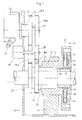
- Fig. 1 ist eine Prinzipskizze einer Rohrtrennmaschine nach der Erfindung insgesamt quer zur Rohrachse gesehen;Fig. 1 is a schematic diagram of a pipe cutting machine according to the invention seen overall transversely to the pipe axis;
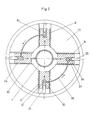
- Fig. 2 ist im Prinzip eine Darstellung der Draufsicht nach 11 von Fig. 1;Fig. 2 is in principle an illustration of the top view of Fig. 1;
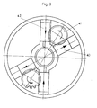
- Fig. 3 stellt im Prinzip die mechanische Druckübertragung zur Kompensation der Fliehkräfte dar.Fig. 3 shows in principle the mechanical pressure transmission to compensate for the centrifugal forces.
Die Maschine dient dem Zweck ein Rohr 1 schnell und sauber in Querrichtung zu trennen. Dabei ist das Rohr in einer nicht dargestellten Haltevorrichtung eines Maschinengestells 10 festgehalten. Die Trennung erfolgt durch zwei radial angeordnete Trennwerkzeuge 15, die beim Trennen umlaufen und dabei in radialer Richtung vorgeschoben werden. Aufgrund dieser Funktion ist ein Antrieb für den Umlauf und einer für den Vorschub erforderlich.The machine serves the purpose of quickly and cleanly cutting a
Die Trennwerkzeuge 15 sind jeweils an einem Werkzeugschlitten 14 befestigt, der radial verschiebbar an einer Scheibe 13 eines Werkzeugträgers 12 befestigt ist. Dieser ist mit seiner Nabe drehbar in einem Lager 11 als Teil des Maschinengestell gelagert. Der Antrieb des Werkzeugträgers erfolgt durch einen Hauptantrieb 18 über Zahnräder 17, 16a und 16.The separating
Die Werkzeugschlitten 14 nehmen jeweils unverschiebbare eine Spindel 22 mit einem Kegelrad 21 auf. Die beiden Kegelräder stehen in Eingriff mit der konischen Verzahnung einer Hohlwelle 20, die drehbar in der Nabe des Werkzeugträgers 12 gelagert ist.The tool slides 14 each immovably accommodate a
Die Hohlwelle ist über Zahnräder 25, 25a, 25b mit dem Ausgang 24 eines Ausgleichsgetriebes 23 verbunden, wobei der Eingang 19 dieses Ausgleichsgetriebes durch die Zahnräder 17 und 17a vom Hauptantrieb 18 angetrieben wird. Das Ausgleichsgetriebe hat einen zweiten Eingang (Ausgleichglied 26) für dessen Antrieb ein Servomotor 27 vorgesehen ist.The hollow shaft is connected via
Die getrieblichen Verbindungen sind so ausgelegt, daß bei Stillstand des Ausgleichsgliedes 26 Werkzeugträger 12 und Hohlwelle 20 synchron umlaufen, was zur Folge hat, daß keine Umdrehungen auf die Kegelräder 21 übertragen werden, d. h. diese und die Spindel stehen still und es findet kein Vorschub statt. Wird jedoch der Servomotor 27 angestellt, und das Ausgleichsglied 26 in der einen oder anderen Richtung bewegt, dann stellt sich zwischen Werkzeugträger und Hohlwelle 20 ein mehr oder weniger großer Unterschied in der Umdrehungszahl ein, wodurch die Spindeln 22 in Drehung versetzt werden und die Werkzeugschlitten 14 in der einen oder anderen Richtung bewegt werden. Die Geschwindigkeit und Beschleunigung des Vorschubs bzw. der Rückbewegung können somit allein durch den Servomotor 27 mit geringem Kraftaufwand gesteuert werden.The gear connections are designed so that when the compensating
Fig. 2 zeigt Einrichtungen, die dazu dienen, die Vorschubelemente bei hohen Umdrehungen zu entlasten. Dabei sind zwei Fiehkraftgewichte 30 radial verschiebbar in Führungen 31 gelagert in einer 90"-Anordnung zu den Vorschubelementen der Trennwerkzeuge 15. An den Fliehkraftgewichten 30 sind Druckräume 32 zur Aufnahme eines hydraulischen oder pneumatischen Druckmediums gebildet. In diese Druckräume ragen jeweils in radialer Anordnung Kolben 33, die an der Scheibe 13 fest abgestützt sind.Fig. 2 shows devices that serve to relieve the feed elements at high revolutions. Two
Mit den Trennwerkzeugen 15 sind jeweils Gegengewichte (Schlitten) 34 fest verbunden, die ebenfalls Druckräume 35 aufweisen mit aufgenommenen Kolben 33. Jeweils ein Druckraum 32 eines Fliehkraftgewichtes steht über eine Leitung 36 mit einem Druckraum eines Schlittens 34 in Verbindung.Counterweights (carriages) 34, which also have
Wenn sich die Scheibe dreht, schieben sich die Fliehkraftgewichte 30 radial nach außen. Das Druckmedium wird unter Druck gesetzt, der sich über die Leitungen 30 in die Druckräume 35 der Schlitten fortsetzt, wo ein zentripetal wirkender Gegendruck erzeugt wird entgegen der Fliehkraft, so daß dadurch die Vorschubelemente der Werkzeugschlitten entlastet werden.When the disc rotates, the
Bei der mechanischen Druckübertragung nach Fig. 3 sind zwei radiale Fliehkraftgewichte 40 vorgesehen, mit Führungen in einer spitzwinkligen Anordnung zu den ebenfalls radial geführten Gegengewichten 42, die mit den Trennwerkzeugen in Verbindung stehen. In der Winkelhalbierenden ist jeweils ein Zahnrad 41 gelagert, das einerseits mit einer linearen Verzahnung am Fliehkraftgewicht 40 und andererseits mit einer linearen Verzahnung im Gegengewicht 42 in Eingriff steht, so daß auf diese Weise die Entlastung der Fliehkraft über eine mechanische Verbindung erfolgt.3, two radial
Claims (5)
gekennzeichnet durch die nachfolgenden weiteren Merkmale:
characterized by the following additional features:
Applications Claiming Priority (2)
| Application Number | Priority Date | Filing Date | Title |
|---|---|---|---|
| DE4123628 | 1991-07-17 | ||
| DE4123628 | 1991-07-17 |
Publications (1)
| Publication Number | Publication Date |
|---|---|
| EP0525406A1 true EP0525406A1 (en) | 1993-02-03 |
Family
ID=6436325
Family Applications (1)
| Application Number | Title | Priority Date | Filing Date |
|---|---|---|---|
| EP92110946A Withdrawn EP0525406A1 (en) | 1991-07-17 | 1992-06-29 | Tube cutting apparatus |
Country Status (1)
| Country | Link |
|---|---|
| EP (1) | EP0525406A1 (en) |
Cited By (14)
| Publication number | Priority date | Publication date | Assignee | Title |
|---|---|---|---|---|
| FR2727886A1 (en) * | 1994-12-12 | 1996-06-14 | Combustible Nucleaire Sicn Soc | TUBE SHAPING DEVICE |
| EP0896846A1 (en) * | 1997-08-14 | 1999-02-17 | SCHULER PRESSEN GmbH & Co. | Trimming apparatus |
| WO2004012894A2 (en) * | 2002-08-01 | 2004-02-12 | The Torrington Company | Bar cutting assembly |
| EP1559494A3 (en) * | 2004-01-29 | 2006-01-18 | SMS Meer GmbH | Device for machining the ends of tubes, especially for cutting threaded connections |
| EP1797984A1 (en) * | 2005-12-16 | 2007-06-20 | Lortz, Hans Joachim | Cutting device for a tube made of plastic band |
| WO2009030210A1 (en) * | 2007-09-06 | 2009-03-12 | CBS Präzisionswerkzeuge GmbH | Tool head |
| CN102009224A (en) * | 2010-11-12 | 2011-04-13 | 吴江市菀坪镙丝厂 | Steel pipe cutting device |
| WO2015119584A1 (en) * | 2014-02-06 | 2015-08-13 | Thaisakol Group Co., Ltd. | Shaft cutting machine that is able to cut short size shaft |
| CN109093184A (en) * | 2018-08-20 | 2018-12-28 | 安徽中鼎金亚汽车管件制造有限公司 | A kind of pipe fitting cutting rolling cut cutter holder assembly |
| CN109175164A (en) * | 2018-09-27 | 2019-01-11 | 江苏天毅冷镦股份有限公司 | A kind of planetary automatic stock cutter |
| CN110280827A (en) * | 2019-07-22 | 2019-09-27 | 常州轻工职业技术学院 | A kind of tube body cutter device and its working method |
| WO2021048259A1 (en) * | 2019-09-10 | 2021-03-18 | Berhalter Ag | Stamping machine for stamping labels and covers |
| CN112605463A (en) * | 2020-12-22 | 2021-04-06 | 兰钰识 | Automatic pipe cutting machine |
| CN113414443A (en) * | 2021-06-24 | 2021-09-21 | 江苏马园电力科技有限公司 | Processing equipment and processing technology for cable protection tube |
Citations (4)
| Publication number | Priority date | Publication date | Assignee | Title |
|---|---|---|---|---|
| DE2542570A1 (en) * | 1975-09-24 | 1977-04-07 | Roehm Guenter H | Radially adjustable jawed chuck - has centrifugal compensating weight between each two jaws with hydraulic pistons sliding in radial channels |
| DE3113072A1 (en) * | 1981-04-01 | 1982-10-14 | Dr. techn. Ernst Linsinger & Co GmbH, 4662 Steyrermühl | "METHOD AND DEVICE FOR SEPARATING COMPARATIVE LONG WORKPIECES, e.g. TUBES, ESPECIALLY AT HIGH TEMPERATURES" |
| DE3231536A1 (en) * | 1982-08-25 | 1984-03-01 | Hessapp Hessische Apparatebau GmbH, 6204 Taunusstein | Jaw chuck |
| EP0426234A2 (en) * | 1989-11-01 | 1991-05-08 | Wavin B.V. | Apparatus and method for the in-line cropping and/or chamfering of a plastic tube |
-
1992
- 1992-06-29 EP EP92110946A patent/EP0525406A1/en not_active Withdrawn
Patent Citations (4)
| Publication number | Priority date | Publication date | Assignee | Title |
|---|---|---|---|---|
| DE2542570A1 (en) * | 1975-09-24 | 1977-04-07 | Roehm Guenter H | Radially adjustable jawed chuck - has centrifugal compensating weight between each two jaws with hydraulic pistons sliding in radial channels |
| DE3113072A1 (en) * | 1981-04-01 | 1982-10-14 | Dr. techn. Ernst Linsinger & Co GmbH, 4662 Steyrermühl | "METHOD AND DEVICE FOR SEPARATING COMPARATIVE LONG WORKPIECES, e.g. TUBES, ESPECIALLY AT HIGH TEMPERATURES" |
| DE3231536A1 (en) * | 1982-08-25 | 1984-03-01 | Hessapp Hessische Apparatebau GmbH, 6204 Taunusstein | Jaw chuck |
| EP0426234A2 (en) * | 1989-11-01 | 1991-05-08 | Wavin B.V. | Apparatus and method for the in-line cropping and/or chamfering of a plastic tube |
Cited By (18)
| Publication number | Priority date | Publication date | Assignee | Title |
|---|---|---|---|---|
| FR2727886A1 (en) * | 1994-12-12 | 1996-06-14 | Combustible Nucleaire Sicn Soc | TUBE SHAPING DEVICE |
| WO1996018475A1 (en) * | 1994-12-12 | 1996-06-20 | Societe Industrielle De Combustible Nucleaire -Sicn- | Tube shaping device |
| EP0896846A1 (en) * | 1997-08-14 | 1999-02-17 | SCHULER PRESSEN GmbH & Co. | Trimming apparatus |
| WO2004012894A2 (en) * | 2002-08-01 | 2004-02-12 | The Torrington Company | Bar cutting assembly |
| WO2004012894A3 (en) * | 2002-08-01 | 2004-05-06 | Torrington Co | Bar cutting assembly |
| EP1559494A3 (en) * | 2004-01-29 | 2006-01-18 | SMS Meer GmbH | Device for machining the ends of tubes, especially for cutting threaded connections |
| EP1797984A1 (en) * | 2005-12-16 | 2007-06-20 | Lortz, Hans Joachim | Cutting device for a tube made of plastic band |
| WO2009030210A1 (en) * | 2007-09-06 | 2009-03-12 | CBS Präzisionswerkzeuge GmbH | Tool head |
| CN102009224A (en) * | 2010-11-12 | 2011-04-13 | 吴江市菀坪镙丝厂 | Steel pipe cutting device |
| WO2015119584A1 (en) * | 2014-02-06 | 2015-08-13 | Thaisakol Group Co., Ltd. | Shaft cutting machine that is able to cut short size shaft |
| CN105939806A (en) * | 2014-02-06 | 2016-09-14 | 塞萨克集团有限公司 | Shaft cutting machine that is able to cut short size shaft |
| CN109093184A (en) * | 2018-08-20 | 2018-12-28 | 安徽中鼎金亚汽车管件制造有限公司 | A kind of pipe fitting cutting rolling cut cutter holder assembly |
| CN109175164A (en) * | 2018-09-27 | 2019-01-11 | 江苏天毅冷镦股份有限公司 | A kind of planetary automatic stock cutter |
| CN110280827A (en) * | 2019-07-22 | 2019-09-27 | 常州轻工职业技术学院 | A kind of tube body cutter device and its working method |
| WO2021048259A1 (en) * | 2019-09-10 | 2021-03-18 | Berhalter Ag | Stamping machine for stamping labels and covers |
| CN112605463A (en) * | 2020-12-22 | 2021-04-06 | 兰钰识 | Automatic pipe cutting machine |
| CN113414443A (en) * | 2021-06-24 | 2021-09-21 | 江苏马园电力科技有限公司 | Processing equipment and processing technology for cable protection tube |
| CN113414443B (en) * | 2021-06-24 | 2022-05-31 | 江苏马园电力科技有限公司 | Processing equipment and processing technology for cable protection tube |
Similar Documents
| Publication | Publication Date | Title |
|---|---|---|
| EP0525406A1 (en) | Tube cutting apparatus | |
| DE3722643C1 (en) | Tool turret | |
| DE2732354B2 (en) | Lathes for non-circular machining, in particular of piston rings | |
| DE2418566A1 (en) | PROCESS AND GRINDING MACHINE FOR THE PROCESSING OF POINTED WORKPIECES | |
| EP0969945B1 (en) | Advancing system for a rotary cutting tool | |
| EP0198223A1 (en) | Machine tool for milling and turning | |
| EP0547388A2 (en) | Chuck for supporting a crankshaft during machining | |
| EP0214624B1 (en) | Machine for broaching cylindrical surfaces of a work piece, preferably of a shaft, particularly of a crankshaft | |
| DE3019627A1 (en) | MACHINE TOOL FOR THE PROCESSING OF ROD MATERIAL | |
| DE3543407C2 (en) | ||
| DE3338240A1 (en) | Device for machining the edges of glass plates | |
| DE2711282A1 (en) | MACHINE FOR FINISHING GEARS | |
| DE2006760B2 (en) | Lathe non-circular rotary installation - uses numerically controlled position motors feeding coupling unit for transmission to tool and holder | |
| DE2339190B2 (en) | Feed drive for tool cross slides on machine tools, in particular on multi-spindle automatic lathes | |
| DE19503772C2 (en) | Pipe and bar peeling machine (rotary peeling machine) | |
| DE2434636C3 (en) | Machine for grinding trochoid surfaces | |
| EP0092634A1 (en) | Machine for circumferential machining | |
| DE1552785C3 (en) | Device for the axial displacement of the milling spindle of a milling machine | |
| CH372225A (en) | Grinding machine for relief grinding of cutting edges provided on the face of a drill, countersink, milling cutter or similar tool | |
| EP0183737B1 (en) | Installation for the manufacturing of components having an internal and/or external polygonal shape | |
| DE2405781C2 (en) | Drive the workpiece spindles of a multi-spindle automatic lathe | |
| DE580900C (en) | Lathe for non-circular turning, in particular for turning angular billets | |
| DE2434254A1 (en) | Multi spindle internal grinding machine - for parallel bores which can be ground by giving the spindles a planetary movement in the holes | |
| DE1961131C3 (en) | Multi-spindle bar lathe | |
| DE2710214C3 (en) | Grinding spindle arrangement |
Legal Events
| Date | Code | Title | Description |
|---|---|---|---|
| PUAI | Public reference made under article 153(3) epc to a published international application that has entered the european phase |
Free format text: ORIGINAL CODE: 0009012 |
|
| AK | Designated contracting states |
Kind code of ref document: A1 Designated state(s): AT DE ES FR GB IT |
|
| 17P | Request for examination filed |
Effective date: 19930212 |
|
| 17Q | First examination report despatched |
Effective date: 19931108 |
|
| STAA | Information on the status of an ep patent application or granted ep patent |
Free format text: STATUS: THE APPLICATION HAS BEEN WITHDRAWN |
|
| 18W | Application withdrawn |
Withdrawal date: 19940111 |