EP0525268B1 - Arm for friction type door check and door check including such arm - Google Patents
Arm for friction type door check and door check including such arm Download PDFInfo
- Publication number
- EP0525268B1 EP0525268B1 EP91402754A EP91402754A EP0525268B1 EP 0525268 B1 EP0525268 B1 EP 0525268B1 EP 91402754 A EP91402754 A EP 91402754A EP 91402754 A EP91402754 A EP 91402754A EP 0525268 B1 EP0525268 B1 EP 0525268B1
- Authority
- EP
- European Patent Office
- Prior art keywords
- arm
- door
- masses
- sectors
- faces
- Prior art date
- Legal status (The legal status is an assumption and is not a legal conclusion. Google has not performed a legal analysis and makes no representation as to the accuracy of the status listed.)
- Expired - Lifetime
Links
Images


Classifications
-
- E—FIXED CONSTRUCTIONS
- E05—LOCKS; KEYS; WINDOW OR DOOR FITTINGS; SAFES
- E05C—BOLTS OR FASTENING DEVICES FOR WINGS, SPECIALLY FOR DOORS OR WINDOWS
- E05C17/00—Devices for holding wings open; Devices for limiting opening of wings or for holding wings open by a movable member extending between frame and wing; Braking devices, stops or buffers, combined therewith
- E05C17/02—Devices for holding wings open; Devices for limiting opening of wings or for holding wings open by a movable member extending between frame and wing; Braking devices, stops or buffers, combined therewith by mechanical means
- E05C17/04—Devices for holding wings open; Devices for limiting opening of wings or for holding wings open by a movable member extending between frame and wing; Braking devices, stops or buffers, combined therewith by mechanical means with a movable bar or equivalent member extending between frame and wing
- E05C17/12—Devices for holding wings open; Devices for limiting opening of wings or for holding wings open by a movable member extending between frame and wing; Braking devices, stops or buffers, combined therewith by mechanical means with a movable bar or equivalent member extending between frame and wing consisting of a single rod
- E05C17/20—Devices for holding wings open; Devices for limiting opening of wings or for holding wings open by a movable member extending between frame and wing; Braking devices, stops or buffers, combined therewith by mechanical means with a movable bar or equivalent member extending between frame and wing consisting of a single rod sliding through a guide
- E05C17/203—Devices for holding wings open; Devices for limiting opening of wings or for holding wings open by a movable member extending between frame and wing; Braking devices, stops or buffers, combined therewith by mechanical means with a movable bar or equivalent member extending between frame and wing consisting of a single rod sliding through a guide concealed, e.g. for vehicles
- E05C17/206—Devices for holding wings open; Devices for limiting opening of wings or for holding wings open by a movable member extending between frame and wing; Braking devices, stops or buffers, combined therewith by mechanical means with a movable bar or equivalent member extending between frame and wing consisting of a single rod sliding through a guide concealed, e.g. for vehicles with elastomeric springs to hold wing open
Abstract
Description
L'invention concerne un dispositif d'arrêt frottant de porte notamment pour une porte de véhicule.The invention relates to a door rubbing stop device in particular for a vehicle door.
On connaît des dispositifs d'arrêt de porte de type frottant essentiellement constitués d'un tirant dont une extrémité est apte à être articulée à la porte et dont l'autre extrémité est libre, et d'un boîtier, fixé au bâti de la porte, qui contient des corps de friction disposés dans le boîtier de part et d'autre d'un passage qui traverse le boîtier et dans lequel peut glisser le tirant, ces corps de friction étant pressés contre le tirant par des moyens élastiques, et le tirant présentant des bossages latéraux qui, en coopérant avec les corps de friction, déterminent des positions d'arrêt du tirant et, par conséquent, des positions d'arrêt de la porte. Un tel dispositif est décrit par exemple dans le brevet FR-A 1 143 995.Friction type door stop devices are known which essentially consist of a tie rod, one end of which is capable of being hinged to the door and the other end of which is free, and of a housing fixed to the frame of the door. , which contains friction bodies arranged in the housing on either side of a passage which passes through the housing and into which the tie rod can slide, these friction bodies being pressed against the tie rod by elastic means, and the tie rod having lateral bosses which, in cooperation with the friction bodies, determine stop positions of the tie rod and, consequently, stop positions of the door. Such a device is described for example in patent FR-A 1 143 995.
On connaît par le document GB-A-2 229 668 un dispositif d'arrêt frottant de porte, notamment pour une porte de véhicule, qui comporte un tirant longitudinal avec des faces planes et un boîtier qui constitue une chambre contenant des corps de friction disposés de part et d'autre d'un passage qui traverse le boîtier et dans lequel peut glisser le tirant, ces corps de friction étant pressés contre le tirant par des moyens élastiques situés dans la chambre. Dans ce document, le tirant est constitué par un insert métallique longitudinal et plat dont les grandes faces sont recouvertes d'un revêtement en matière polymère dont l'epaisseur est variable pour former des bossages sur les faces planes du tirant, ces bossages étant aptes à déterminer des positions d'arrêt du tirant, les corps de pression sont constitués par des roulements et les moyens élastiques sont constitués par des ressorts. Un tel dispositif est de construction complexe et de fonctionnement bruyant.Document GB-A-2 229 668 discloses a door rubbing stop device, in particular for a vehicle door, which comprises a longitudinal tie rod with flat faces and a housing which constitutes a chamber containing friction bodies arranged on either side of a passage which passes through the housing and into which the tie rod can slide, these friction bodies being pressed against the tie rod by elastic means located in the chamber. In this document, the tie rod is constituted by a flat longitudinal metal insert, the large faces of which are covered with a coating of polymer material, the thickness of which is variable to form bosses on the flat faces of the tie rod, these bosses being suitable for determine stop positions of the tie rod, the bodies of pressure are constituted by bearings and the elastic means are constituted by springs. Such a device is of complex construction and noisy operation.
La présente invention a pour objet d'améliorer un tel dispositif, notamment pour le rendre moins bruyant, moins sensible à l'usure et tel que l'usure ne constitue pas un risque de corrosion.The object of the present invention is to improve such a device, in particular to make it less noisy, less sensitive to wear and such that wear does not constitute a risk of corrosion.
La présente invention y parvient grâce aux caractéristiques énoncées dans la revendication 1.The present invention achieves this by virtue of the features set out in claim 1.
On décrira ci-après un exemple d'un dispositif d'arrêt de porte conforme à l'invention, en référence aux figures du dessin joint, et la description et les figures feront apparaître d'autres particularités de l'invention.An example of a door stop device according to the invention will be described below, with reference to the figures of the attached drawing, and the description and the figures will reveal other particularities of the invention.
Sur les figures :
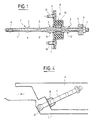
- la figure 1 est une coupe longitudinale du dispositif selon le plan I-I de la figure 2 ;
- la figure 2 est une coupe suivant le plan II-II de la figure 1 ;
- la figure 3 est une perspective éclatée du dispositif ;
- la figure 4 est un schéma d'un exemple d'implantation du dispositif, et
- la figure 5 est un schéma montrant différentes positions du tirant au cours du fonctionnement du dispositif.
- Figure 1 is a longitudinal section of the device according to the plane II of Figure 2;
- Figure 2 is a section along the plane II-II of Figure 1;
- Figure 3 is an exploded perspective of the device;
- FIG. 4 is a diagram of an example of installation of the device, and
- Figure 5 is a diagram showing different positions of the tie rod during operation of the device.
Le dispositif d'arrêt de porte représenté sur les figures 1 à 3 est constitué d'un tirant T et d'un boîtier B.The door stop device shown in Figures 1 to 3 consists of a tie rod T and a housing B.
Le tirant T est constitué d'un plat longitudinal en acier 1 d'épaisseur constante dont les deux grandes faces 2,2' opposées sont recouvertes d'un revêtement en matière polymère, de préférence en une matière polyamide. L'épaisseur du revêtement est variable ; cette variation d'épaisseur détermine des bossages 3,3' répartis sur la longueur du tirant T, de façon connue en soi. Les petits côtés du tirant T sont de préférence également enrobés de la matière polymère.The tie rod T consists of a longitudinal steel plate 1 of constant thickness, the two opposite
A une extrémité, le tirant T comporte un orifice 4 pour son montage sur le bâti d'une porte (ou sur la porte) et, à son autre extrémité, le tirant T comporte un ensemble de butée constitué par exemple d'un amortisseur élastique 5 et renfort métallique 6 qui sont enfilés sur le tirant T et maintenus par une clavette 7 passant dans un orifice 8 du tirant.At one end, the tie-rod T comprises an
Le boîtier B est constitué d'un fond 9 et d'un couvercle 10 qui comporte des orifices 11 coopérant pour le passage de vis 12 servant à fixer le boîtier à la porte (ou au bâti de la porte). Le fond 9 et le couvercle 10 coopèrent pour déterminer une chambre interne et sont munis de deux lumières en vis-a-vis 13,14 aptes à laisser passer le tirant T qui peut ainsi traverser la chambre.The housing B consists of a
Dans la chambre, est contenu un corps 15 en matière élastomère constitué de deux masses 16,17 de forme générale parallélépipédique en vis-à-vis réunies par des ligaments 18 qui déterminent entre eux et entre les deux masses 16,17 un espace suffisant pour loger deux secteurs métalliques 19,20 et pour laisser passer entre les secteurs le tirant T introduit dans les lumières 13,14.In the chamber, there is contained a
Le volume et la conformation de la chambre sont étudiés en rapport avec la conformation des masses 16,17 et des secteurs 19,20 pour que les secteurs soient en permanence appliqués avec pression contre les grandes faces du tirant et que le corps 15 puisse se déformer élastiquement au passage des bossages du tirant sans être jamais comprimé contre les surfaces du boîtier B qui sont perpendiculaires aux grandes faces 2,2' du tirant T.The volume and the conformation of the chamber are studied in relation to the conformation of the
Dans une solution préférée, les masses 16,17 ont une base rectangulaire ou carrée et un sommet tronc-pyramidal et les faces des secteurs 19,20 qui sont au contact du tirant T ont des formes convexes adaptées au profil du tirant T.In a preferred solution, the
Les faces des masses 16,17 qui sont parallèles au sens de glissement du tirant T comportent de préférence des parties en creux et des parties en relief (par exemple des stries).The faces of the
Les bossages 3,3' du tirant T ont des pentes dont les inclinaisons sont choisies différentes selon les efforts de frottement souhaités.The bosses 3.3 ′ of the tie rod T have slopes whose inclinations are chosen to be different depending on the friction forces desired.
Durant l'ouverture ou la fermeture de la porte, le tirant T se déplace dans le boîtier B entre les deux secteurs 19,20. Les deux secteurs 19,20, en contact permanent avec le tirant T, subissent les variations d'épaisseurs du tirant T (bossages) comprimant les masses 16,17 élastomères contre le boîtier B. Les efforts les plus importants ont lieu lors du passage des bossages 3,3' contre les secteurs 19,20.During the opening or closing of the door, the tie rod T moves in the housing B between the two
L'usure entre les secteurs 19,20 et le tirant T est subie essentiellement par le tirant T. Les pièces métalliques du boitier B (boîtier-couvercle et secteurs) ne subissent pas de corrosion car le boîtier B et le couvercle 10 ne subissent aucun frottement, donc conservent leur revêtement de protection, et les secteurs 19,20 ne sont pas usés par le tirant T. Du fait de l'absence de contact métal-métal, le dispositif ne génère aucun bruit de fonctionnement.The wear between the
La figure 5 illustre le fonctionnement (en soi connu) du dispositif qui permet de maintenir la porte en position fermée (I), en position d'ouverture moyenne (II) et en position d'ouverture maximale (III).FIG. 5 illustrates the operation (in itself known) of the device which makes it possible to maintain the door in the closed position (I), in the medium open position (II) and in the maximum open position (III).
Claims (5)
- A friction door-check, in particular for a vehicle door, the door-check comprising a longitudinal arm (T) having plane faces and a housing (B) which constitutes a chamber containing friction bodies disposed on either side of a passage passing through the housing (B) and in which the arm (T) can slide, said friction bodies being pressed against the arm (T) by resilient means situated in the chamber, said arm being constituted by a flat longitudinal metal insert (1) whose large faces (2, 2') are covered in a coating of polymer material of varying thickness to form projections (3, 3') on the plane faces of the arm (T), said projections (3, 3') being suitable for defining stop positions for the arm (T), the door-check being characterized in that the resilient means are constituted by a body (15) of elastomer material formed by two masses (16, 17) generally in the form of rectangular parallelepipeds that are interconnected by ligaments (18) which define between themselves and between the two masses (16, 17) sufficient space to receive two metal sectors (19, 20) constituting the friction bodies and between them pressing against the large faces (2, 2') of the arm under the resilient effect obtained by compression of the masses (16, 17) against the housing (B), whereby firstly the door-check is silent in operation because of the absence of any metal-on-metal contact, and secondly the wear between the sectors and the arm occurs essentially on the arm.
- A door-check according to claim 1, characterized in that the volume and the shape of the chamber are so designed with regard to the shapes of the masses (16, 17) and of the sectors (19, 20) that the sectors (19, 20) are pressed permanently against the large faces (2, 2') of the arm (T), and the body (15) can deform elastically as the projections (3, 3') of the arm (T) go past without ever being compressed against the surfaces of the housing (B) that are perpendicular to the large faces of the arm (T).
- A door-check according to claim 2, characterized in that the masses (16, 17) have respective rectangular or square bases associated with ends in the form of a truncated pyramids, and in that the faces of the sectors which are in contact with the arm (T) have convex shapes adapted to the profile of the arm (T).
- A door-check according to any one of claims 1 to 3, characterized in that the faces of the masses (16, 17) which are parallel to the sliding direction of the arm (T) include portions that are hollow and portions that are in relief.
- A door-check according to any one of claims 1 to 4, characterized in that the small sides of the arm (T) are also coated in polymer material.
Applications Claiming Priority (2)
| Application Number | Priority Date | Filing Date | Title |
|---|---|---|---|
| FR9108882 | 1991-07-15 | ||
| FR9108882A FR2679287B1 (en) | 1991-07-15 | 1991-07-15 | TIE ROD FOR FRICTION-TYPE DOOR STOP DEVICE AND DOOR STOP DEVICE COMPRISING SAME. |
Publications (2)
| Publication Number | Publication Date |
|---|---|
| EP0525268A1 EP0525268A1 (en) | 1993-02-03 |
| EP0525268B1 true EP0525268B1 (en) | 1995-06-14 |
Family
ID=9415090
Family Applications (1)
| Application Number | Title | Priority Date | Filing Date |
|---|---|---|---|
| EP91402754A Expired - Lifetime EP0525268B1 (en) | 1991-07-15 | 1991-10-15 | Arm for friction type door check and door check including such arm |
Country Status (5)
| Country | Link |
|---|---|
| EP (1) | EP0525268B1 (en) |
| AT (1) | ATE123840T1 (en) |
| DE (1) | DE69110461T2 (en) |
| ES (1) | ES2074242T3 (en) |
| FR (1) | FR2679287B1 (en) |
Cited By (1)
| Publication number | Priority date | Publication date | Assignee | Title |
|---|---|---|---|---|
| DE4207706B4 (en) * | 1992-03-11 | 2004-05-27 | ED. SCHARWäCHTER GMBH | Stepless door arrester for motor vehicle doors |
Families Citing this family (10)
| Publication number | Priority date | Publication date | Assignee | Title |
|---|---|---|---|---|
| GB2266338B (en) * | 1992-03-21 | 1996-05-15 | Ihw Eng Ltd | Door check mechanism |
| FR2733533B1 (en) * | 1995-04-27 | 1997-07-25 | Coutier Moulage Gen Ind | DOOR STOP OR THE LIKE, ESPECIALLY FOR A MOTOR VEHICLE |
| DE29606304U1 (en) * | 1996-04-05 | 1996-06-27 | Fingscheidt Gmbh Friedr | Door holders for vehicle doors |
| DE19822098A1 (en) * | 1998-05-16 | 1999-11-18 | Ernst Behm | Door arrester |
| ES2190945T3 (en) | 2000-04-14 | 2003-09-01 | Gammastamp Spa | BUMPER DEVICE FOR THE DOOR OF A VEHICLE. |
| US6687953B1 (en) | 2000-10-13 | 2004-02-10 | Ventra Group Inc. | Torsion spring door check device |
| DE102004016138A1 (en) * | 2004-04-01 | 2005-10-20 | Bayerische Motoren Werke Ag | Automotive door stay dampening profile has a head with gusset transition to guide rod collar with countersunk hole |
| DE602007002394D1 (en) * | 2007-07-02 | 2009-10-22 | Gammastamp Spa | Doorstop for vehicles |
| EP2354395B1 (en) | 2010-02-03 | 2014-08-27 | Gammastamp S.p.A. | A door-stop device for vehicles |
| CN108442834A (en) * | 2017-12-08 | 2018-08-24 | 丰业迪睦斯(芜湖)汽车部件有限公司 | automobile limiter shell structure |
Family Cites Families (5)
| Publication number | Priority date | Publication date | Assignee | Title |
|---|---|---|---|---|
| US2321409A (en) * | 1937-05-17 | 1943-06-08 | Nat Stamping Company | Door check |
| FR1143995A (en) * | 1956-03-22 | 1957-10-08 | Boyriven Sa | Tie rod forming door stopper for automobiles |
| FR1414880A (en) * | 1964-09-07 | 1965-10-22 | Cousin Freres Sa | Door stop device in the open position applicable in particular to motor vehicle doors |
| DE3515883A1 (en) * | 1985-05-03 | 1986-11-06 | Siegfried 5620 Velbert Klingenburg | Door stop provided with fastening flanges, especially for motor-vehicle doors |
| JPH02253912A (en) * | 1989-03-28 | 1990-10-12 | Aisin Chem Co Ltd | Method of manufacturing lever for door check |
-
1991
- 1991-07-15 FR FR9108882A patent/FR2679287B1/en not_active Expired - Fee Related
- 1991-10-15 DE DE69110461T patent/DE69110461T2/en not_active Expired - Fee Related
- 1991-10-15 EP EP91402754A patent/EP0525268B1/en not_active Expired - Lifetime
- 1991-10-15 ES ES91402754T patent/ES2074242T3/en not_active Expired - Lifetime
- 1991-10-15 AT AT91402754T patent/ATE123840T1/en not_active IP Right Cessation
Cited By (1)
| Publication number | Priority date | Publication date | Assignee | Title |
|---|---|---|---|---|
| DE4207706B4 (en) * | 1992-03-11 | 2004-05-27 | ED. SCHARWäCHTER GMBH | Stepless door arrester for motor vehicle doors |
Also Published As
| Publication number | Publication date |
|---|---|
| DE69110461D1 (en) | 1995-07-20 |
| DE69110461T2 (en) | 1996-02-08 |
| ATE123840T1 (en) | 1995-06-15 |
| FR2679287A1 (en) | 1993-01-22 |
| ES2074242T3 (en) | 1995-09-01 |
| FR2679287B1 (en) | 1995-11-10 |
| EP0525268A1 (en) | 1993-02-03 |
Similar Documents
| Publication | Publication Date | Title |
|---|---|---|
| EP0525268B1 (en) | Arm for friction type door check and door check including such arm | |
| EP0241319A1 (en) | Door check, especially for vehicle doors | |
| KR970002042A (en) | Belt tensioner | |
| US2408145A (en) | Garment hanger | |
| RU99101944A (en) | LOOP MECHANISM | |
| US4332056A (en) | Infinite position door hold-open | |
| US6581243B2 (en) | Hinge with built-in door stop | |
| FR2363720A1 (en) | BINDING TAPE FOR TWO METAL PIECES | |
| FR2657823A1 (en) | MECHANISM COVER, ESPECIALLY FOR THE OPENING ROOF OF A MOTOR VEHICLE. | |
| BE831756A (en) | DEVICE FOR LIMITING THE OPENING ANGLE OF THE SLEEVE OF A WINDOW OR A DOOR OR SIMILAR BODY | |
| EP0867586B1 (en) | Hinge for a door or swingpanel, especially for a glass panel | |
| EP2203618B1 (en) | Device acting as a stand-off between an opening element and a fixed element, particularly of a motor vehicle | |
| US1842734A (en) | Door holding device | |
| US4827669A (en) | Glass stabilizer for vehicle door assembly | |
| FR2626822A1 (en) | Elastic stop-piece, particularly for a motor vehicle bodywork element, and motor vehicle opening panel equipped with at least one stop-piece | |
| EP0039259B1 (en) | Window lifting device, especially for automotive-vehicle doors | |
| CN212359432U (en) | Embedded hinge | |
| JPH0334466Y2 (en) | ||
| US2718393A (en) | Leaf spring spacing structures and anchorages therefor | |
| FR2663103A1 (en) | Friction disc for articulation bearing, with damping | |
| CN111997464A (en) | Embedded hinge | |
| DE20121912U1 (en) | A door stay | |
| JPH0617974Y2 (en) | Stop force adjustment mechanism for stop device in concealed door closer | |
| FR2757807A1 (en) | Closing mechanism for a radial opening in a guide rail | |
| EP0303099A1 (en) | Improvements in the weatherstrips |
Legal Events
| Date | Code | Title | Description |
|---|---|---|---|
| PUAI | Public reference made under article 153(3) epc to a published international application that has entered the european phase |
Free format text: ORIGINAL CODE: 0009012 |
|
| AK | Designated contracting states |
Kind code of ref document: A1 Designated state(s): AT BE CH DE DK ES FR GB GR IT LI LU NL SE |
|
| 17P | Request for examination filed |
Effective date: 19930712 |
|
| 17Q | First examination report despatched |
Effective date: 19931018 |
|
| GRAA | (expected) grant |
Free format text: ORIGINAL CODE: 0009210 |
|
| AK | Designated contracting states |
Kind code of ref document: B1 Designated state(s): AT BE CH DE DK ES FR GB GR IT LI LU NL SE |
|
| PG25 | Lapsed in a contracting state [announced via postgrant information from national office to epo] |
Ref country code: NL Free format text: LAPSE BECAUSE OF NON-PAYMENT OF DUE FEES Effective date: 19950614 Ref country code: GR Free format text: LAPSE BECAUSE OF FAILURE TO SUBMIT A TRANSLATION OF THE DESCRIPTION OR TO PAY THE FEE WITHIN THE PRESCRIBED TIME-LIMIT Effective date: 19950614 Ref country code: DK Effective date: 19950614 Ref country code: AT Effective date: 19950614 |
|
| REF | Corresponds to: |
Ref document number: 123840 Country of ref document: AT Date of ref document: 19950615 Kind code of ref document: T |
|
| ITF | It: translation for a ep patent filed |
Owner name: ING. MILANI GIORGIO |
|
| REF | Corresponds to: |
Ref document number: 69110461 Country of ref document: DE Date of ref document: 19950720 |
|
| GBT | Gb: translation of ep patent filed (gb section 77(6)(a)/1977) |
Effective date: 19950710 |
|
| REG | Reference to a national code |
Ref country code: ES Ref legal event code: FG2A Ref document number: 2074242 Country of ref document: ES Kind code of ref document: T3 |
|
| PG25 | Lapsed in a contracting state [announced via postgrant information from national office to epo] |
Ref country code: SE Effective date: 19950914 |
|
| PG25 | Lapsed in a contracting state [announced via postgrant information from national office to epo] |
Ref country code: LU Free format text: LAPSE BECAUSE OF NON-PAYMENT OF DUE FEES Effective date: 19951031 Ref country code: LI Effective date: 19951031 Ref country code: CH Effective date: 19951031 |
|
| NLV1 | Nl: lapsed or annulled due to failure to fulfill the requirements of art. 29p and 29m of the patents act | ||
| PLBE | No opposition filed within time limit |
Free format text: ORIGINAL CODE: 0009261 |
|
| STAA | Information on the status of an ep patent application or granted ep patent |
Free format text: STATUS: NO OPPOSITION FILED WITHIN TIME LIMIT |
|
| 26N | No opposition filed | ||
| REG | Reference to a national code |
Ref country code: CH Ref legal event code: PL |
|
| PGFP | Annual fee paid to national office [announced via postgrant information from national office to epo] |
Ref country code: GB Payment date: 20001013 Year of fee payment: 10 |
|
| PGFP | Annual fee paid to national office [announced via postgrant information from national office to epo] |
Ref country code: ES Payment date: 20001023 Year of fee payment: 10 |
|
| PGFP | Annual fee paid to national office [announced via postgrant information from national office to epo] |
Ref country code: FR Payment date: 20001026 Year of fee payment: 10 |
|
| PGFP | Annual fee paid to national office [announced via postgrant information from national office to epo] |
Ref country code: DE Payment date: 20001114 Year of fee payment: 10 |
|
| PGFP | Annual fee paid to national office [announced via postgrant information from national office to epo] |
Ref country code: BE Payment date: 20001204 Year of fee payment: 10 |
|
| PG25 | Lapsed in a contracting state [announced via postgrant information from national office to epo] |
Ref country code: GB Free format text: LAPSE BECAUSE OF NON-PAYMENT OF DUE FEES Effective date: 20011015 |
|
| PG25 | Lapsed in a contracting state [announced via postgrant information from national office to epo] |
Ref country code: ES Free format text: LAPSE BECAUSE OF NON-PAYMENT OF DUE FEES Effective date: 20011016 |
|
| PG25 | Lapsed in a contracting state [announced via postgrant information from national office to epo] |
Ref country code: BE Free format text: LAPSE BECAUSE OF NON-PAYMENT OF DUE FEES Effective date: 20011031 |
|
| REG | Reference to a national code |
Ref country code: GB Ref legal event code: IF02 |
|
| BERE | Be: lapsed |
Owner name: SOC. FINANCIERE D' ETUDE ET DE DEVELOPPEMENT INDU Effective date: 20011031 |
|
| GBPC | Gb: european patent ceased through non-payment of renewal fee |
Effective date: 20011015 |
|
| PG25 | Lapsed in a contracting state [announced via postgrant information from national office to epo] |
Ref country code: FR Free format text: LAPSE BECAUSE OF NON-PAYMENT OF DUE FEES Effective date: 20020628 |
|
| PG25 | Lapsed in a contracting state [announced via postgrant information from national office to epo] |
Ref country code: DE Free format text: LAPSE BECAUSE OF NON-PAYMENT OF DUE FEES Effective date: 20020702 |
|
| REG | Reference to a national code |
Ref country code: FR Ref legal event code: ST |
|
| REG | Reference to a national code |
Ref country code: ES Ref legal event code: FD2A Effective date: 20021113 |
|
| PG25 | Lapsed in a contracting state [announced via postgrant information from national office to epo] |
Ref country code: IT Free format text: LAPSE BECAUSE OF NON-PAYMENT OF DUE FEES;WARNING: LAPSES OF ITALIAN PATENTS WITH EFFECTIVE DATE BEFORE 2007 MAY HAVE OCCURRED AT ANY TIME BEFORE 2007. THE CORRECT EFFECTIVE DATE MAY BE DIFFERENT FROM THE ONE RECORDED. Effective date: 20051015 |