EP0524623B1 - Video telephone - Google Patents
Video telephone Download PDFInfo
- Publication number
- EP0524623B1 EP0524623B1 EP92112580A EP92112580A EP0524623B1 EP 0524623 B1 EP0524623 B1 EP 0524623B1 EP 92112580 A EP92112580 A EP 92112580A EP 92112580 A EP92112580 A EP 92112580A EP 0524623 B1 EP0524623 B1 EP 0524623B1
- Authority
- EP
- European Patent Office
- Prior art keywords
- voice
- image
- signal
- camera
- data
- Prior art date
- Legal status (The legal status is an assumption and is not a legal conclusion. Google has not performed a legal analysis and makes no representation as to the accuracy of the status listed.)
- Expired - Lifetime
Links
Images


Classifications
-
- H—ELECTRICITY
- H04—ELECTRIC COMMUNICATION TECHNIQUE
- H04N—PICTORIAL COMMUNICATION, e.g. TELEVISION
- H04N21/00—Selective content distribution, e.g. interactive television or video on demand [VOD]
- H04N21/20—Servers specifically adapted for the distribution of content, e.g. VOD servers; Operations thereof
- H04N21/23—Processing of content or additional data; Elementary server operations; Server middleware
- H04N21/238—Interfacing the downstream path of the transmission network, e.g. adapting the transmission rate of a video stream to network bandwidth; Processing of multiplex streams
- H04N21/2383—Channel coding or modulation of digital bit-stream, e.g. QPSK modulation
-
- H—ELECTRICITY
- H04—ELECTRIC COMMUNICATION TECHNIQUE
- H04N—PICTORIAL COMMUNICATION, e.g. TELEVISION
- H04N21/00—Selective content distribution, e.g. interactive television or video on demand [VOD]
- H04N21/20—Servers specifically adapted for the distribution of content, e.g. VOD servers; Operations thereof
- H04N21/23—Processing of content or additional data; Elementary server operations; Server middleware
- H04N21/236—Assembling of a multiplex stream, e.g. transport stream, by combining a video stream with other content or additional data, e.g. inserting a URL [Uniform Resource Locator] into a video stream, multiplexing software data into a video stream; Remultiplexing of multiplex streams; Insertion of stuffing bits into the multiplex stream, e.g. to obtain a constant bit-rate; Assembling of a packetised elementary stream
-
- H—ELECTRICITY
- H04—ELECTRIC COMMUNICATION TECHNIQUE
- H04N—PICTORIAL COMMUNICATION, e.g. TELEVISION
- H04N21/00—Selective content distribution, e.g. interactive television or video on demand [VOD]
- H04N21/40—Client devices specifically adapted for the reception of or interaction with content, e.g. set-top-box [STB]; Operations thereof
- H04N21/43—Processing of content or additional data, e.g. demultiplexing additional data from a digital video stream; Elementary client operations, e.g. monitoring of home network or synchronising decoder's clock; Client middleware
- H04N21/434—Disassembling of a multiplex stream, e.g. demultiplexing audio and video streams, extraction of additional data from a video stream; Remultiplexing of multiplex streams; Extraction or processing of SI; Disassembling of packetised elementary stream
-
- H—ELECTRICITY
- H04—ELECTRIC COMMUNICATION TECHNIQUE
- H04N—PICTORIAL COMMUNICATION, e.g. TELEVISION
- H04N21/00—Selective content distribution, e.g. interactive television or video on demand [VOD]
- H04N21/40—Client devices specifically adapted for the reception of or interaction with content, e.g. set-top-box [STB]; Operations thereof
- H04N21/43—Processing of content or additional data, e.g. demultiplexing additional data from a digital video stream; Elementary client operations, e.g. monitoring of home network or synchronising decoder's clock; Client middleware
- H04N21/438—Interfacing the downstream path of the transmission network originating from a server, e.g. retrieving MPEG packets from an IP network
- H04N21/4382—Demodulation or channel decoding, e.g. QPSK demodulation
-
- H—ELECTRICITY
- H04—ELECTRIC COMMUNICATION TECHNIQUE
- H04N—PICTORIAL COMMUNICATION, e.g. TELEVISION
- H04N7/00—Television systems
- H04N7/14—Systems for two-way working
- H04N7/141—Systems for two-way working between two video terminals, e.g. videophone
-
- H—ELECTRICITY
- H04—ELECTRIC COMMUNICATION TECHNIQUE
- H04N—PICTORIAL COMMUNICATION, e.g. TELEVISION
- H04N7/00—Television systems
- H04N7/14—Systems for two-way working
- H04N7/141—Systems for two-way working between two video terminals, e.g. videophone
- H04N7/142—Constructional details of the terminal equipment, e.g. arrangements of the camera and the display
-
- H—ELECTRICITY
- H04—ELECTRIC COMMUNICATION TECHNIQUE
- H04N—PICTORIAL COMMUNICATION, e.g. TELEVISION
- H04N7/00—Television systems
- H04N7/14—Systems for two-way working
- H04N7/141—Systems for two-way working between two video terminals, e.g. videophone
- H04N7/147—Communication arrangements, e.g. identifying the communication as a video-communication, intermediate storage of the signals
-
- H—ELECTRICITY
- H04—ELECTRIC COMMUNICATION TECHNIQUE
- H04N—PICTORIAL COMMUNICATION, e.g. TELEVISION
- H04N7/00—Television systems
- H04N7/14—Systems for two-way working
- H04N7/141—Systems for two-way working between two video terminals, e.g. videophone
- H04N7/148—Interfacing a video terminal to a particular transmission medium, e.g. ISDN
-
- H—ELECTRICITY
- H04—ELECTRIC COMMUNICATION TECHNIQUE
- H04Q—SELECTING
- H04Q11/00—Selecting arrangements for multiplex systems
- H04Q11/04—Selecting arrangements for multiplex systems for time-division multiplexing
- H04Q11/0428—Integrated services digital network, i.e. systems for transmission of different types of digitised signals, e.g. speech, data, telecentral, television signals
- H04Q11/0435—Details
- H04Q11/0471—Terminal access circuits
-
- H—ELECTRICITY
- H04—ELECTRIC COMMUNICATION TECHNIQUE
- H04Q—SELECTING
- H04Q2213/00—Indexing scheme relating to selecting arrangements in general and for multiplex systems
- H04Q2213/003—Constructional details
-
- H—ELECTRICITY
- H04—ELECTRIC COMMUNICATION TECHNIQUE
- H04Q—SELECTING
- H04Q2213/00—Indexing scheme relating to selecting arrangements in general and for multiplex systems
- H04Q2213/337—Picturephone
Definitions
- This invention relates to a video telephone according to the pre-characterizing part of claim 1, and in particular to a color motion-picture video telephone for communication of voice, image and other data in real time through a digital communication network.
- a color motion-picture video telephone which has a unitary structure composed of: a handset for communication of voice; a voice CODEC, a camera, a display and an image CODEC for communication of an image; and a communication controller for controlling such communications.
- a single camera is tiltable between a normal horizontal position in which it can shoot the speaker in front of the telephone and a tilted position in which it can shoot a picture or a piece of writing placed on a desk or the like.
- the conventional video telephone is disadvantageous in that the speaker must hold the handset in one hand for voice communication and that the camera has only a limited range of shooting.
- the camera When shooting a picture or writing, the camera itself cuts off illumination of an interior lamp to throw a shadow over the picture or writing. Consequently there has been a requirement for a more convenient video telephone equipped with a wider variety of functions.
- EP-A-O 436 345 A2 discloses a communication apparatus such as a television telephone connected to the [SDN, having a calling party number display service, comprising a receiving unit for receiving image data sent from a calling party communication apparatus, a memory for storing the image data received received by the receiving unit in correspondence to ID data indicative of the calling party commnication apparatus, and a display apparatus for receiving the ID data upon call reception from the calling party communicating apparatus and for reading out the image data corresponding to the received data from the memory and for displaying.
- the object of the present invention is to provide a video telephone which provides enhanced functionality. This object is achieved by a video telephone according to claim 1. Further embodiments are defined in the dependent claims.
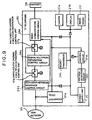
- reference numeral 21a designates a camera; 21b, a display; 21c, a camera lamp; 21, a camera-and-display unit including the camera 21a, the display 21b and the lamp 21c; and 22, an image CODEC.
- the image CODEC 22 includes a character superimposing circuit 22a, a video switching circuit 22b, an image output circuit 22c, a display processing circuit for controlling the display mode of the display screen, an image input circuit 22e, an image decoding circuit 22f for reproducing a picture signal from a received digital image signal, and an image encoding circuit 22g for converting a picture signal, which is outputted by the image input circuit 22e, into a digital signal for communication control described below.
- reference numeral 23 designates a key panel unit which includes an LED display control circuit 23a, a video-telephone-function key control circuit 23b, and a dial key control circuit 23c.
- Designated by 23d is a FAX key for controlling facsimile transmission.
- Numeral 24 designates a communication controller which includes a signal-multiplex-separation control circuit 24a, an ISDN-user-network interface control circuit 24b, a microprocessor 24c for controlling various parts of the video telephone, a voice communication control circuit 24d, a hold-function control circuit 24e, a timer circuit 24f, a speaker 24g, a sounder 24h for generating a particular sound, and an analog switch circuit 24i.
- the communication controller 24 also includes a hands-free control circuit 24j, a built-in microphone 24k, an analog-to-digital converter circuit 24l for the facsimile interface, an analog level converter circuit 24m for the facsimile interface, and an interface circuit 24n for camera control.
- Numeral 25 designates a power supply unit for inputting a commercial supply of power from an external source via a commercial power supply plug 20 to supply a constant voltage to the camera-and-display unit 21, the image CODEC 22 and the communication controller 24.
- Numeral 26 designates a handset connected to a mainframe of the telephone by a cable.
- Numeral 27 designates an ISDN-user-network interface terminal; 28a, a camera-control-signal input/output terminal; 28b, a serial-data input/output terminal; 28c, a facsimile terminal; 29a, a voice input terminal; 29b, a voice output terminal; 29c, an external microphone input terminal; 29b, an image input terminal; and 29e, an image output terminal.
- These terminals are input/output connectors provided on the rear surface of the mainframe of the telephone.
- the image processing devices may be contained on a single sheet (e.g., A4 size) of image CODEC substrate by integrating each of the image encoding circuit 22g and the image decoding circuit 22f on a single very small semiconductor chip.
- the communication controller 24 all parts except the speaker 24g and the microphone 24k may be contained on a single sheet (e.g., A4 size) of communication controller substrate by integrating the ISDN-user-network interface control circuit 24b and the voice communication control circuit 24d on a single very small semiconductor chip and also integrating the signal-multiplex-separation control circuit 24, etc. on a single very small semiconductor chip.
- the speaker 24g and the microphone 24k are directly attached to a mainframe 19 of the telephone.
- the power supply unit, the two circuit substrates, the key panel unit 23 and the camera-and-display unit 21 as well as cables connecting these units are contained within the telephone, resulting in a unitary compact video telephone.
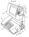
- FIG. 2 shows the structure of the video telephone.
- reference numerals 21b and 12a respectively designate the display and the camera, both at the head or top of an L-shaped body.
- 13 designates the image CODEC 22 containing the image CODEC substrate, occupying the neck or vertical support portion of the L-shaped body.
- 18 designates a mainframe containing the communication controller 24, the key panel unit 23, the power supply unit 25, the built-in speaker 24g and the built-in microphone 24k, occupying the bottom or base portion of the L-shaped body.
- the key panel unit 23 is equipped with telephone-function keys, video telephone control keys and indicator lamps.
- 26 designates the handset.
- the mainframe 18 is equipped with external input/output terminals, as described below.
- the image CODEC 13 is located between the camera 21a, the camera-and-display unit 21b and the communication control system, which includes the signal-multiplex-separation control circuit 24a, the ISDN-user-network interface control circuit 24b. Therefore it is possible to simplify the wiring between the substrates and hence to realize a compactly unitized video telephone. Further, since air flows from the lower side to the upper side of the vertical substrate, the image CODEC 13 will have an increased heat radiation.
- the camera 12a contains an auto-focusing compact color camera 21a and a lamp 21c, and is accommodated in a camera holder 12d angularly movably attached to the display 21b.
- the camera holder 12d is angularly movable between a normal horizontal position shown in FIG. 1, and a tilted position in which the camera 21a can shoot downwardly.
- Mounted on the camera holder 12d or the display 21b is a switch that will be turned on in response to the angular movement of the camera holder 12d over a predetermined angle with respect to the display 21b. While this switch is on, the microprocessor 24c controls the lamp 21c to be illuminated.
- the microprocessor 24c controls the lamp 21c to turn on/off according to a predetermined key input on the key panel unit 23.
- the camera holder 12d has a resilient mold complementary in shape to the joint end of the camera 12a so that the camera 12a can be attached to the camera holder 12d by being pressed into the camera holder 12d.
- the camera 12a may be removed from the camera holder 12d.
- the camera 12a may be vertically slidable over a predetermined distance with respect to the camera holder 12d.
- the camera 21a may be slidable with respect to the camera 12a longitudinally along a shooting slot of the camera 12a.
- the camera 12a is connected to the mainframe 18 by a set cable of necessary signal lines and a power supply line.
- reference numeral 12c designates a switch for switching over between automatic iris and manual iris of the camera 21a
- 12b designates a fader type switch for illumination intensity adjustment.
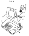
- FIG. 3 shows the camera 12a having been removed from the camera holder 12d; in this position, the camera 21a can shoot in any desired direction.
- FIG. 4 shows various kinds of input/output terminals provided on the rear surface of the television telephone.
- reference numeral 72 designates a commercial power supply cord for introducing an AC 100 V commercial power supply from an external source.
- the power supply is switched on and off by a power supply switch 71.
- the ISDN-user-network interface terminal 27 is a communication interface normally connected with a dedicated cord.
- a voice signal (such as of that from a tape recorder) may be inputted via a dedicated cord.
- an external speaker or the like is connected via a dedicated cord to generate received speech.
- an image signal (such as a television image signal or an external camera image signal) may be inputted via a dedicated cord.
- a television receiver or the like may be connected via a dedicated cord to output a received image.
- a cable with an RS-232C interface connector may be connected to perform serial-digital-data transfer with, for example, a personal computer.
- a cable with a dedicated digital interface connector may be connected to control and operate cooperatively with an external camera controller.
- an external microphone is connected to the external microphone input terminal 29c, it is automatically switched over from inputting a voice signal via the built-in microphone to inputting a voice signal via the external microphone.
- an external facsimile may be connected to the facsimile terminal 28c.
- FIG. 5 shows the arrangement of keys on the key panel unit 23.
- a telephone-function key group 81, a video-telephone-control-function key group 82 and a dial key group 83 are arranged so as to occupy the respective three sections.
- LEDs are provided on the respective distal key heads of five function keys for indicating whether the voice-switching function (A-SW), the image-switching function (V-SW), the picture-quality-switching (high-picture-quality) function, the hands-free function and the camera function are set respectively. Therefore the user can easily ascertain the status of each function.
- a power supply indication lamp 84 is turned on if the power supply switch 71 is switched on, and is turned off if the power supply switch 71 is switched off or if the power supply from an external source is cut off.
- An indication lamp 85 starts flashing simultaneously with the output of a call sound.
- the speaker key is used in operating the hands-free function of the telephone-function key group 81.
- the ISDN-user-network interface control circuit 24b is equipped with output/input signal terminals for the input/output terminals, which correspond to 2B channels of the ISDN-user-network interface, of the signal-multiplex-separation control circuit 24a, and the ISDN-user-network interface input/output terminal 27.
- the ISDN-user-network interface control circuit 24b inputs a 2B-channel digital signal containing voice, image and data signals that are multiplexed by the signal-multiplex-separation control circuit 24a, multiplexes this inputted signal with a D-channel (16 kbps) signal, which is a communication line control signal, generates a signal equivalent to 2B plus D channels of the ISDN base interface and outputs this signal to the network.
- the ISDN-user-network interface control circuit 24b also inputs a signal equivalent to 2B plus D channels from the network, and separates a signal equivalent to 2B channel and outputs the separated signal to the signal-multiplex-separation control circuit 24a. Calling the destination terminal in order to be connected via the network, and controlling communication to connect with and disconnect from the destination terminal, are performed by the ISDN-user-network interface control circuit 24b.
- the signal-multiplex-separation control circuit 24a has digital signal input/output functions for voice, image and data systems and multiplexes the digital signals of these three systems, i.e., the image inputted from the image encoding circuit 22g, the voice inputted from the voice communication control circuit 24d, and the data inputted from the microprocessor 24c, the camera control interface circuit 24n or the analog-to-digital converter circuit 24l, and sends them to the ISDN-user-network interface control circuit 24b as the digital signal equivalent to 2B (2X64 kbps) channels.
- the ISDN-user-network interface control circuit 24b separates the received 2B-channel digital signal into digital signals of the three systems and outputs the image to the image decoding circuit 22f, the voice to the voice communication control circuit 24d and the data to the microprocessor 24c, the camera control interface circuit 24n or the analog-to-digital converter circuit 24l.
- the total signal transmission speeds of the individual systems can be set optionally to a value equivalent to 2B channels, i.e. below 128 kbps; that is, bidirectional multiplex communication control by an arbitrary combination including the voice signal transmission speed of 56 kbps, the image signal transmission speed of 64 kbps and the data signal transmission speed of 8 kbps can be performed.
- the communication control is performed by the transmission method according to CCITT recommendations H. 221 and H. 242.
- the microprocessor 24c receives the setting of the signal transmission speeds of the individual systems by a special key input or a combination of key inputs from various kinds of keys of FIG. 5 and controls the signal-multiplex-separation control circuit 24a.
- the setting of the signal transmission speed is received by depressing the FAX key.
- the setting of the signal transmission speed of each system may be received by indicating a predetermined menu on the display and depressing a menu key to make a key input corresponding to the menu.
- the signal-multiplex-separation control circuit 24a controls the function of the image CODEC 22, the lighting function of the LED indication control circuit 23a, the switching function of the video switching circuit 22b and the switching function of the analog switch circuit 24i.
- the microprocessor 24c which has a program connected in a memory, performs the function control of the image CODEC 22 via the signal-multiplex-separation control circuit 24a, the input/output control of the key panel unit 23 and the hardware control such as setting and maintaining the three-system multiplex-separation control of voice, image and data as well as the man-machine interface control such as message output to the display screen.
- the timer circuit 24f is a circuit for outputting data about the current data and time, notifying the microprocessor 24c of parameters indicating the time and indicating the current time and communication time period.
- the color image signal obtained by the camera 21a is outputted to the video switching circuit 22b.
- the video switching circuit 22b selects an external image input signal or an image signal of the character superimposing circuit 22a and outputs the selected signal to the image input circuit 22e.
- the image input circuit 22e distributes the output signal of the video switching circuit 22b to an display processing circuit 22d and the image encoding circuit 22g.
- the image signal inputted to the image encoding circuit 22g is encoded into a digital image signal compressed to the data transmission speed suitable for the transmission band of the transmission lines according to CCITT recommendation H. 261 and outputs the digital image signal to the signal-multiplex-separation control circuit 24a.
- the camera image signal or the external image input signal can be selected and can be sent to the ISDN-user-network interface as the digital image signal.
- the digital image signal outputted from the image-signal-system output terminal of the signal-multiplex-separation control circuit 24a is decoded into an analog image signal according to CCITT recommendation H. 261 by the image decoding circuit 22f, and the analog image signal is then outputted to the image output circuit 22c.
- the display processing circuit 22d converts the image signal (transmitted image signal) outputted from the image input circuit 22e into a mirror image or a point-symmetrical image which is inverted by 180 degrees and outputs the converted image signal to the image output circuit 22c. Under the control of the microprocessor 24c, the display processing circuit 22d selects a miner screen display mode or a normal whole screen display mode.
- the image output circuit 22c inputs the image signal, which is outputted from the image decoding circuit 22f, and outputs the image signal to the character superimposing circuit 22a under the control of the microprocessor 24c.
- the image output circuit 22c also selects a miner screen display or a normal whole screen display.
- the image to be outputted on the miner screen section is an output signal of the display processing circuit 22d.
- the character superimposing circuit 22a inputs the image signal, which is outputted from the image output circuit 22c, and outputs the image signal to display it on the screen of the display 21b.
- the character superimposing circuit 22a also superimposes, for example, a registered graphic or a character over the output image signal of the image output circuit 22c to display the resulting signal on the display screen.
- the voice communication control circuit 24d inputs the voice signal from the signal-multiplex-separation control circuit 24a, decodes the analog voice signal, outputs the decoded voice signal to the analog switch circuit 24i, then encodes the analog voice signal, which is inputted from the analog switch circuit 24i, into the digital voice signal and outputs the digital voice signal to the signalmultiplex-separation control circuit 24a.
- the hold-function control circuit 24e When it sets a hold status during communication, the hold-function control circuit 24e outputs a hold sound to the source-side handset or the destination-side handset.
- the sounder 24h generates a call sound.
- the analog switch circuit 24i In response to depression of the voice switch-over key on the key panel, the analog switch circuit 24i is controlled by the microprocessor 24c. According to the control of the microprocessor 24c, the analog switch circuit 24i selects the voice signal or the external voice input signal to be sent as the signal source to be outputted to the voice communication control circuit 24d.
- the hands-free control circuit 24j In response to the depression of the speaker key on the key panel, the hands-free control circuit 24j is controlled the microprocessor 24c. According to the control of the microprocessor 24c, the hands-free control circuit 24j selects the voice input/output path according to the built-in microphone 24k and the speaker 24g instead of the handset 26. If the voice input/output path according to the built-in microphone 24k and the speaker 24g is selected, the hands-free control circuit 24j compares the input signal of the built-in microphone 24k in level with the output signal of the speaker 24g and allows the higher-level signal to pass and cuts off the lower-level signal. It is therefore possible to prevent oscillation, i.e., howling due to the positive feedback loop so that an excellent hands-free communication using the built-in microphone 24k and the speaker 24g can be realized.
- the analog-to-digital converter circuit 24l converts the analog signal, which is converted in level by the analog level converter circuit 24m, and also takes the data signal to convert it into a specific-level analog signal.
- the analog level converter circuit 24m matches the input/output signal level of the analog-to-digital converter circuit 24l with the input/output level of the facsimile connected to the facsimile terminal 28c.
- the camera control interface circuit 24n outputs four kinds of digital control signals, i.e. panning, tilting, focusing and zooming signals for controlling the external camera, via the camera-control-signal input/output terminal 28a.
- the input/output digital signal of the analog-to-digital converter circuit 24l or the input/output digital signal of the camera control interface circuit 24n is selected by the switch that is controlled by the microprocessor 24c, and is then transmitted to the destination telephone from the ISDN-user-network interface terminal 27 after having passed through the signal-multiplex-separation control circuit 24a as the data signal.
- the microprocessor 24c controls the switch so that the data signal, which is to be inputted/outputted to the signal-multiplex-separation, is connected with the analog-to-digital converter circuit 24l.
- the microprocessor 24c also controls the data transmission rate to set 64 kbps for data and the remaining 64 kbps for voice and image so that facsimile transmission is possible.
- the transmission channel of 64 kbps for facsimile is set bidirectionally so that transmission between analog facsimiles is possible.
- the signal-multiplex-separation control circuit 24a sends the bit-rate-allocated code to the destination-side telephone, and upon receipt of this code, the destination-side telephone is automatically switched over to the facsimile transmission mode.
- the camera controller and the camera control controller are connected to the camera-control-signal input/output terminal 28a of the video telephone of this embodiment and in which the motion of the external camera connected to the image input terminal 29e of the destination-side telephone is to be remotely controlled.
- FIG. 6 shows the system structure in this case.
- reference numerals 50a and 50b designate two video telephones of FIG. 2; 51a and 51b, ISDN-user-network interface control circuits (corresponding to the circuit 24b of FIG. 1); 52a and 52b, signal-multiplex-separation control circuits (corresponding to the circuits 24a of FIG. 1); 53a and 53b, camera control interface circuits (corresponding to the circuits 24n of FIG. 1); 54, a camera control controller; 55, a camera controller; 56, an external camera; and 57, an ISDN network.
- connection between the video telephone 50a and the camera controller 55 and the connection between the unitary video telephone 50b and the camera control controller 54 are made by respective dedicated cables (four signals).
- the camera control digital signals generated by the camera control controller 54 are inputted to the camera control interface circuit 53b as parallel signals.
- the camera control interface circuit 53b converts the inputted data into serial data which is then inputted to the data port of the signal-multiplex-separation control circuit 52b as data signals. Then the data signals are multiplexed together with voice and image signals, and the multiplexed signals are outputted to the ISDN network 57 via the ISDN-user-network interface control circuit 51b.
- the multiplexed signal is received by the video telephone 50a, which is the destination side of the video telephone 50b, and is separated into voice, image and data signals in the signal-multiplex-separation control circuit 52a via the ISDN-user-network interface control circuit 51a, and out of the voice, image and data signals, the data signal is reproduced to four parallel signals via the camera control interface circuit 53a, and these parallel signals are outputted to the camera controller 55.
- the camera controller 55 controls vertical movement (tilting), horizontal movement (panning), focusing and zooming of the external camera 56.
- the camera position of the destination-side telephone can be controlled with ease by ensuring the display of the source-side telephone.
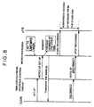
- reference numeral 60 designates a video telephone which comprises the microprocessor 24c, the signal-multiplex-separation control circuit 24a, the image CODEC 22, the voice communication control circuit 24d and the ISDN-user-network interface control circuit 24b. Further, 66 designates an external video tape recorder, and 67, an ISDN network.
- FIG. 8 shows the procedures to realize the caretaker voice/image recording operation with this structure.
- the source-side video telephone is set to the caretaker mode by the key panel.
- the setting of the caretaker mode displays a predetermined menu on the display 21b according to the menu key shown in FIG. 5, so that the input as set will be received.
- the microprocessor 24c controls various parts so as to perform automatic receiving communication.
- the ISDN-user-network control circuit 24b automatically performs the communication receiving operation, notifies the microprocessor 24c of this receipt and detects the telephone number of the destination-side telephone from the received information so as to be able to store the number in the built-in memory.
- the telephone at this end of the line transmits the absence message to the telephone at the other end to notify that the person at this end is absent.
- the absence message may be predetermined image information stored in the video tape recorder 66 or may be predetermined image information that is stored in other data storage means.
- the microprocessor 24c instructs the external video tape recorder 66 to start recording.
- the video tape recorder 66 is previously connected to the external voice output terminal 29b and the image output terminal 29e of the telephone at this end via respective cables. Between the microprocessor 24c and the video tape recorder 66, a remote-control signal line of the video tape recorder 66 is connected.
- the unitary video telephone 60 After having received any message from the telephone at the other end, the unitary video telephone 60 that has received from the network a notice of disconnect due to the disconnect of a call from the telephone at the other end controls the video tape recorder 66 to stop recording and then returns to the standby state.
- the video telephone of this embodiment may operate the voice communicating function using a local power supply taken from the ISDN network, as described below.
- FIG. 9 shows this kind of video telephone for realizing the foregoing operation.
- the video telephone 90 comprises an ISND-user-network interface control circuit 24b, a signal-multiplex-separation control circuit 24a, a microprocessor 24c, a voice communication control circuit 24d, a handset 26, an image CODEC 22, the camera 21a and a display 21b.
- reference numeral 91a designates a DC-to-DC converter for converting a d.c. voltage from the local source into a constant voltage; 91b, a power source; 91c, a voltage detector circuit for detecting whether or not a commercial power supply is present; 91d, a control circuit for realizing the voice communication function while the commercial power supply is cut off; 97a and 97b, switches for causing a multiplex-separation control unit 93 to be bypassed so that the amount of electric power to be consumed in the circuit at the time of local power supply can be reduced; and 99, an ISDN network.
- the voltage detector circuit 91c detects the absence of the external power supply and gives such notice to the control circuit 91d.
- the control circuit 91d causes the signal-multiplex-separation control circuit 24a to be bypassed in order to save on the amount of electric power to be consumed and controls the switches 97a, 97b in such a manner that the voice signal is connected to the voice communication control circuit 24d directly by the ISDN-user-network interface control circuit 24b.
- the DC-to-DC converter 91a reduces a d.c. voltage from a local power source into a constant d.c. voltage and supplies the voltage only to the circuit that realizes the voice communication function.
- the control circuit 91d sets the ISDN-user-network interface control circuit 24d in such a manner that a telephone controller 95 is controlled by the ISDN-user-network interface control circuit 24b.
- the power supply unit 25 may be equipped with a charger and a charge control circuit for normally charging the charger with the local supply power until the charged electric power exceeds a value capable of driving the entire system for a constant time and for supplying to various parts the electric power charged in the charger when the power supply is cut off, so that not only the voice communication function but also the entire system can be operated in the same manner as when the power supply is not cut off.
- the video telephone may be equipped with a memory for storing telephone numbers, the names of the owners of the telephones and other information as well as image information about the owner such as an identification picture, so that when receiving a message, if the calling telephone number can be found in the memory, the name and information of the owner as well as image information will be indicated on the display.
- the video telephone may be equipped with a memory for storing a plurality of telephone numbers, so that if the telephone number of the other end is not stored in the memory even in the automatic transmission mode, the control may be forcibly switched over to the manual transmission mode.
- the video telephone of this invention since it is equipped with a lamp, it is possible to shoot a picture, a piece of writing or an other document well.
- the video telephone can also be connected with an analog facsimile machine, and enables communication without holding the handset, thanks to the hands-free function.
Description
Claims (12)
- A video telephone for exchanging image data, voice data and user data through digital communication lines in real time, comprising:characterized bycommunication control means (24) for controlling communication of image data, voice data and user data through the communication lines;a multiplex-separation control unit (24a) for multiplexing image data, voice data and user data onto said digital communication lines and separating multiplexed image data, voice data and user data from said digital communication lines;a camera (21a) for producing an image signal;an image codec unit (22) for coding the image signal produced by said camera (21a) into image data and then transmitting said image data to said multiplex-separation control unit (24a) and for decoding image data separated by said multiplex-separation control unit (24a) into an image signal;a display (21b) for displaying an image represented by the image signal decoded by said image codec unit (22);a microphone (24k) for producing a voice signal;a voice communication control unit (24d) for coding the voice signal produced by said microphone into voice data and then transmitting said voice data to said multiplex-separation control unit (24a) and for decoding voice data separated by said multiplex-separation control unit (24a) into a voice signal;a speaker for outputting a voice represented by the voice signal decoded by said voice communication control unit (24d);user data input/output terminal means (28a, 28b, 28c) for inputting user data and then transmitting to said multiplex-separation control unit (24a) and for outputting the user data separated by said multiplex-separation control unit (24a); andsaid communication control means (24) comprising a microprocessor (24c), which is adapted to control allocation of the data transmission rate between image data, voice data and user data when said multiplex-separation control unit (24a) multiplexes image data, voice data and user data.
- A video telephone according to claim 1, further comprising:an image input terminal (29d) for inputting an image signal;a video switch unit (22b) for outputting the image signal from said camera (21a) or said image input terminal (29d) to said image codec unit (22) to code into image data;an image output terminal (29e) for outputting the image signal decoded by said image codec unit (22);a voice input terminal (29a) for inputting a voice signal;an audio switch unit (24i) for outputting the voice signal from said microphone (24k) or said voice input terminal (29a) to said voice communication control unit (24d) to code into voice data;a voice output terminal (29b) for outputting the voice signal decoded by said voice communication control unit (24d);and wherein said user data input/output terminal (28a, 28b, 28c) includes a serial data interface (28b), a facsimile terminal (28c), and camera control terminal (28a),said multiplex-separation control unit (24a) includes a selector for switching over inputting and outputting of the user data between said multiplex-separation control unit (24a) and each of said serial data input/output interface (28b), said facsimile terminal (28c) and said camera control terminal (28a),said communication control means (24) controls said video switch unit (22b), said audio switch unit (24i) and selector.
- A video telephone according to claim 1, further comprising:a handset (26) for outputting a voice according to the voice signal decoded by said voice communication control unit (24d) and for producing a voice signal;a first audio switch for outputting the voice signal produced by said microphone or said handset to said voice communication control unit (24d) to code into voice data; anda second audio switch for outputting the voice signal from said voice communication control unit (24d) to said handset or said speaker.
- A video telephone according to claim 1, wherein said facsimile terminal (28c) includes a digital-to-analog converter for converting the user data separated by said multiplex separation control unit (24a) into an analog signal;a facsimile input/output terminal for outputting the analog signal converted by said digital-to-analog converter to a facsimile and for inputting an analog signal from said facsimile; andan analog-to-digital converter for converting the analog signal inputted through said facsimile input/output terminal into digital data and for outputting the digital data to said multiplex separation control unit (24a) as user data.
- A video telephone according to one of the preceding claims, further comprisingan external camera (56) connected to an image input terminal of said video telephone; anda camera controller (55) connected to a camera control terminal of said video telephone for controlling panning, tilting, zooming and focusing operations of said external camera (56).
- A video telephone according to one of claims 1 to 5, further comprising:a camera unit (12a) accommodating said camera (21a) and a lamp (21c) for illuminating a subject to be taken by said camera, said camera unit being angularly movably connected to said display (21b).
- A video telephone according to one of claims 1 to 5, further comprising:a camera unit (12a) accommodating said camera (21a), which is connected to said image codec (22) by a cable, for outputting the image signal, which is taken by said camera (21a), to said image codec (22) as the image signal to be coded, said camera unit (12a) being detachably connected with said display (21b).
- A video telephone according to claim 7, wherein said camera (21a) is slidably mounted in said camera unit (12a), said camera unit (12a) being slidably attached to said display (21b).
- A video telephone system comprising a video telephone according to claim 3, a video tape recorder (66), a memory for storing image data, and a video tape recorder control signal terminal for outputting a video tape recorder control signal instructing an action of said video tape recorder (66) by said communication control means (24);wherein said video tape recorder (66) is connected to said image output terminal, said voice output terminal and said video tape recorder control signal terminal; andwherein for incoming data after caretaker image recording is designated by a key of said key input unit, said control unit of said video telephone reads the image data from said memory to send the same image data to said multiplex separation control unit (24a), outputs the input image signal and the voice signal respectively to said image output terminal and said voice output terminal, and outputs to said video tape recorder control signal terminal a video tape recorder control signal instructing picture and voice recording actions.
- A video telephone according to claim 1, further comprising:a power supply unit (25) for receiving supply power form an external power supply and for distributing the power to various parts and being adapted for receiving supply power from said power supply unit (25) including a voltage converter for converting a voltage of said supply of power from said external source into an internal voltage to be used in said video telephone; a detector for detecting an interruption of said external power source; and a power distributor for distributing power from said digital communication lines to said various parts if said detector detects the interruption of said external power source.
- A video telephone according to claim 10, wherein said power supply unit (25) includes:a charger for charging the supply of power from said external source; a detector for detecting an interruption of said supply of power from said external source; and a power distributor for distributing a power charged by said charger to said various parts if said detector detects the interruption of said external power source.
- A video telephone according to claim 6, wherein said camera unit (12a) has means for illuminating said lamp (21c) while said camera unit (21a) is angularly movably over a predetermined angle with respect to said display (21b).
Applications Claiming Priority (2)
| Application Number | Priority Date | Filing Date | Title |
|---|---|---|---|
| JP184669/91 | 1991-07-24 | ||
| JP3184669A JPH0530502A (en) | 1991-07-24 | 1991-07-24 | Integrated video telephone set |
Publications (3)
| Publication Number | Publication Date |
|---|---|
| EP0524623A2 EP0524623A2 (en) | 1993-01-27 |
| EP0524623A3 EP0524623A3 (en) | 1993-10-27 |
| EP0524623B1 true EP0524623B1 (en) | 1998-09-30 |
Family
ID=16157291
Family Applications (1)
| Application Number | Title | Priority Date | Filing Date |
|---|---|---|---|
| EP92112580A Expired - Lifetime EP0524623B1 (en) | 1991-07-24 | 1992-07-23 | Video telephone |
Country Status (6)
| Country | Link |
|---|---|
| US (1) | US5400068A (en) |
| EP (1) | EP0524623B1 (en) |
| JP (2) | JPH0530502A (en) |
| AU (1) | AU644748B2 (en) |
| CA (1) | CA2074540C (en) |
| DE (1) | DE69227157T2 (en) |
Cited By (1)
| Publication number | Priority date | Publication date | Assignee | Title |
|---|---|---|---|---|
| USD425053S (en) | 1999-01-04 | 2000-05-16 | Lucent Technologies Inc. | Housing for a display telephone unit |
Families Citing this family (97)
| Publication number | Priority date | Publication date | Assignee | Title |
|---|---|---|---|---|
| US5587735A (en) * | 1991-07-24 | 1996-12-24 | Hitachi, Ltd. | Video telephone |
| EP0500091B1 (en) * | 1991-02-20 | 1998-07-15 | Hitachi, Ltd. | Television telephone |
| EP0778704A3 (en) * | 1991-07-15 | 1997-08-20 | Hitachi Ltd | Teleconference module |
| EP0773686B1 (en) | 1991-07-15 | 1999-11-10 | Hitachi, Ltd. | Equipment for a teleconference |
| DE4236176A1 (en) * | 1992-10-27 | 1994-05-05 | Sel Alcatel Ag | Image call-up answering device for paperless central archives - stores and plays back image and speed information on VTR, and has LCD display on ISDN telephone to indicate programme menu |
| CA2108872C (en) * | 1993-01-28 | 1997-09-16 | David B. Smith | Audio/video telephone communications |
| US6323894B1 (en) * | 1993-03-12 | 2001-11-27 | Telebuyer, Llc | Commercial product routing system with video vending capability |
| JP3472594B2 (en) * | 1993-04-28 | 2003-12-02 | 株式会社日立製作所 | Television dialogue system and central office |
| JPH0795418A (en) * | 1993-09-20 | 1995-04-07 | Canon Inc | Picture communication equipment |
| GB2282906B (en) | 1993-10-13 | 1996-11-06 | Dataquill Ltd | Data enty systems |
| US6009305A (en) * | 1993-12-28 | 1999-12-28 | Hitachi Denshi Kabushiki Kaisha | Digital video signal multiplex transmission system |
| US5701581A (en) * | 1993-12-28 | 1997-12-23 | Hitachi Denshi Kabushiki Kaisha | Method for bidirectionally transmitting digital video signal and digital video signal bidirectional transmission system |
| US6345390B1 (en) | 1993-12-28 | 2002-02-05 | Hitachi Denshi Kabushiki Kaisha | Bidirectional digital signal transmission system and repeater for the same |
| US5734414A (en) * | 1994-03-03 | 1998-03-31 | Matsushita Electric Industrial Co., Ltd. | Camera apparatus for electronic conference |
| DE4415167A1 (en) | 1994-04-29 | 1995-11-02 | Siemens Ag | Telecommunications arrangement for transmitting images |
| US5802281A (en) | 1994-09-07 | 1998-09-01 | Rsi Systems, Inc. | Peripheral audio/video communication system that interfaces with a host computer and determines format of coded audio/video signals |
| JPH08111858A (en) * | 1994-10-12 | 1996-04-30 | Hitachi Ltd | Video interactive monitor system |
| EP0719016B1 (en) * | 1994-12-01 | 2006-02-22 | Sharp Kabushiki Kaisha | Communication equipment |
| US5821995A (en) * | 1994-12-23 | 1998-10-13 | Hitachi Denshi Kabushiki Kaisha | Method and apparatus for controlling transmission of multiplexed video signals |
| KR0137699B1 (en) * | 1994-12-24 | 1998-05-15 | 김광호 | A circuit and method for processing self screen video telephone |
| WO1996041473A1 (en) * | 1995-06-07 | 1996-12-19 | Technical Visions, Inc. | Videophone messaging system |
| US5712903A (en) * | 1995-08-21 | 1998-01-27 | Bell Atlantic Network Services, Inc. | Split intelligent peripheral for broadband and narrowband services |
| US5666153A (en) * | 1995-10-03 | 1997-09-09 | Virtual Shopping, Inc. | Retractable teleconferencing apparatus |
| US5760824A (en) * | 1995-12-29 | 1998-06-02 | Lucent Technologies Inc. | Multimedia telephone having wireless camera and television module and method of operation thereof |
| GB9600804D0 (en) | 1996-01-17 | 1996-03-20 | Robb Garry D | Multiphone |
| US5894512A (en) * | 1996-07-26 | 1999-04-13 | Ncr Corporation | Method and apparatus for routing voice and video calls to a group of agents |
| AU4894297A (en) * | 1996-10-03 | 1998-04-24 | Motorola, Inc. | Apparatus, method and system for wireline audio and video conferencing and telephony |
| US6654060B1 (en) * | 1997-01-07 | 2003-11-25 | Canon Kabushiki Kaisha | Video-image control apparatus and method and storage medium |
| US5877821A (en) * | 1997-01-30 | 1999-03-02 | Motorola, Inc. | Multimedia input and control apparatus and method for multimedia communications |
| AU2223999A (en) * | 1998-01-12 | 1999-07-26 | David Monroe | Apparatus for capturing, converting and transmitting a visual image signal via adigital transmission system |
| US6480510B1 (en) * | 1998-07-28 | 2002-11-12 | Serconet Ltd. | Local area network of serial intelligent cells |
| KR100318941B1 (en) * | 1998-10-12 | 2002-04-22 | 윤종용 | Image communication apparatus and method of communication terminal |
| JP3475809B2 (en) * | 1998-10-14 | 2003-12-10 | 株式会社デンソー | Portable videophone |
| JP2000148108A (en) * | 1998-11-09 | 2000-05-26 | Hitachi Ltd | Image display device |
| US6577605B1 (en) | 1999-06-18 | 2003-06-10 | Viewcast.Com, Inc. | System, method and apparatus for automatically distributing multimedia calls |
| US6956826B1 (en) | 1999-07-07 | 2005-10-18 | Serconet Ltd. | Local area network for distributing data communication, sensing and control signals |
| SG85166A1 (en) * | 2000-01-21 | 2001-12-19 | Guang Jin Yang | Visual telephone capable of displaying synchronously quadruplex input signals and method thereof |
| US6407341B1 (en) | 2000-04-25 | 2002-06-18 | International Business Machines Corporation | Conductive substructures of a multilayered laminate |
| GB0011747D0 (en) * | 2000-05-17 | 2000-07-05 | Butterworth Martyn | Improvements related to telecoms |
| KR100463219B1 (en) * | 2001-03-15 | 2004-12-23 | 에스케이 텔레콤주식회사 | Image communication system |
| KR20020074945A (en) * | 2001-03-23 | 2002-10-04 | 포토폴리오(주) | A digital camera for PC having a shadow elimination means |
| US20030179860A1 (en) * | 2002-03-22 | 2003-09-25 | Multisuns Corp. | Apparatus and method for recording meeting and/or teleconference |
| US7404001B2 (en) * | 2002-03-27 | 2008-07-22 | Ericsson Ab | Videophone and method for a video call |
| JP4031949B2 (en) * | 2002-05-07 | 2008-01-09 | 弥吉郎 酒井 | Information communication equipment |
| US20040162637A1 (en) | 2002-07-25 | 2004-08-19 | Yulun Wang | Medical tele-robotic system with a master remote station with an arbitrator |
| US6925357B2 (en) * | 2002-07-25 | 2005-08-02 | Intouch Health, Inc. | Medical tele-robotic system |
| US7643168B2 (en) | 2003-01-03 | 2010-01-05 | Monroe David A | Apparatus for capturing, converting and transmitting a visual image signal via a digital transmission system |
| US7813836B2 (en) | 2003-12-09 | 2010-10-12 | Intouch Technologies, Inc. | Protocol for a remotely controlled videoconferencing robot |
| US20060007473A1 (en) * | 2004-07-07 | 2006-01-12 | Erin Zhu | Videophone having integrated facsimile machine |
| US8077963B2 (en) | 2004-07-13 | 2011-12-13 | Yulun Wang | Mobile robot with a head-based movement mapping scheme |
| US7425977B2 (en) | 2004-08-10 | 2008-09-16 | Yakichiro Sakai | Interactive communication apparatus |
| US9198728B2 (en) | 2005-09-30 | 2015-12-01 | Intouch Technologies, Inc. | Multi-camera mobile teleconferencing platform |
| US20070291128A1 (en) * | 2006-06-15 | 2007-12-20 | Yulun Wang | Mobile teleconferencing system that projects an image provided by a mobile robot |
| US8849679B2 (en) | 2006-06-15 | 2014-09-30 | Intouch Technologies, Inc. | Remote controlled robot system that provides medical images |
| TWI310870B (en) * | 2006-07-10 | 2009-06-11 | Avermedia Information Inc | Modular document camera |
| US9160783B2 (en) | 2007-05-09 | 2015-10-13 | Intouch Technologies, Inc. | Robot system that operates through a network firewall |
| US10875182B2 (en) | 2008-03-20 | 2020-12-29 | Teladoc Health, Inc. | Remote presence system mounted to operating room hardware |
| US8179418B2 (en) | 2008-04-14 | 2012-05-15 | Intouch Technologies, Inc. | Robotic based health care system |
| US8170241B2 (en) | 2008-04-17 | 2012-05-01 | Intouch Technologies, Inc. | Mobile tele-presence system with a microphone system |
| US9193065B2 (en) | 2008-07-10 | 2015-11-24 | Intouch Technologies, Inc. | Docking system for a tele-presence robot |
| US9842192B2 (en) | 2008-07-11 | 2017-12-12 | Intouch Technologies, Inc. | Tele-presence robot system with multi-cast features |
| US8340819B2 (en) | 2008-09-18 | 2012-12-25 | Intouch Technologies, Inc. | Mobile videoconferencing robot system with network adaptive driving |
| US8996165B2 (en) | 2008-10-21 | 2015-03-31 | Intouch Technologies, Inc. | Telepresence robot with a camera boom |
| US9138891B2 (en) | 2008-11-25 | 2015-09-22 | Intouch Technologies, Inc. | Server connectivity control for tele-presence robot |
| US8463435B2 (en) | 2008-11-25 | 2013-06-11 | Intouch Technologies, Inc. | Server connectivity control for tele-presence robot |
| US8849680B2 (en) | 2009-01-29 | 2014-09-30 | Intouch Technologies, Inc. | Documentation through a remote presence robot |
| US8897920B2 (en) | 2009-04-17 | 2014-11-25 | Intouch Technologies, Inc. | Tele-presence robot system with software modularity, projector and laser pointer |
| US8384755B2 (en) | 2009-08-26 | 2013-02-26 | Intouch Technologies, Inc. | Portable remote presence robot |
| US11399153B2 (en) | 2009-08-26 | 2022-07-26 | Teladoc Health, Inc. | Portable telepresence apparatus |
| US20110149811A1 (en) | 2009-12-23 | 2011-06-23 | Ramprakash Narayanaswamy | Web-Enabled Conferencing and Meeting Implementations with Flexible User Calling Features |
| US20110149809A1 (en) | 2009-12-23 | 2011-06-23 | Ramprakash Narayanaswamy | Web-Enabled Conferencing and Meeting Implementations with Flexible User Calling and Content Sharing Features |
| US8914734B2 (en) | 2009-12-23 | 2014-12-16 | 8X8, Inc. | Web-enabled conferencing and meeting implementations with a subscription-based model |
| US20110150194A1 (en) | 2009-12-23 | 2011-06-23 | Ramprakash Narayanaswamy | Web-Enabled Conferencing and Meeting Implementations with Flexible User Calling Features |
| US11154981B2 (en) | 2010-02-04 | 2021-10-26 | Teladoc Health, Inc. | Robot user interface for telepresence robot system |
| US8670017B2 (en) | 2010-03-04 | 2014-03-11 | Intouch Technologies, Inc. | Remote presence system including a cart that supports a robot face and an overhead camera |
| US10343283B2 (en) | 2010-05-24 | 2019-07-09 | Intouch Technologies, Inc. | Telepresence robot system that can be accessed by a cellular phone |
| US10808882B2 (en) | 2010-05-26 | 2020-10-20 | Intouch Technologies, Inc. | Tele-robotic system with a robot face placed on a chair |
| JP2012119815A (en) * | 2010-11-30 | 2012-06-21 | Brother Ind Ltd | Terminal device, communication control method, and communication control program |
| US9264664B2 (en) | 2010-12-03 | 2016-02-16 | Intouch Technologies, Inc. | Systems and methods for dynamic bandwidth allocation |
| US9323250B2 (en) | 2011-01-28 | 2016-04-26 | Intouch Technologies, Inc. | Time-dependent navigation of telepresence robots |
| WO2012103525A2 (en) | 2011-01-28 | 2012-08-02 | Intouch Technologies, Inc. | Interfacing with a mobile telepresence robot |
| US10769739B2 (en) | 2011-04-25 | 2020-09-08 | Intouch Technologies, Inc. | Systems and methods for management of information among medical providers and facilities |
| JP5776313B2 (en) | 2011-04-28 | 2015-09-09 | 株式会社リコー | Conference equipment |
| US9098611B2 (en) | 2012-11-26 | 2015-08-04 | Intouch Technologies, Inc. | Enhanced video interaction for a user interface of a telepresence network |
| US20140139616A1 (en) | 2012-01-27 | 2014-05-22 | Intouch Technologies, Inc. | Enhanced Diagnostics for a Telepresence Robot |
| US8817801B1 (en) | 2011-07-08 | 2014-08-26 | 8X8, Inc. | Conferencing and meeting implementations with advanced features |
| US8836751B2 (en) | 2011-11-08 | 2014-09-16 | Intouch Technologies, Inc. | Tele-presence system with a user interface that displays different communication links |
| US9251313B2 (en) | 2012-04-11 | 2016-02-02 | Intouch Technologies, Inc. | Systems and methods for visualizing and managing telepresence devices in healthcare networks |
| US8902278B2 (en) | 2012-04-11 | 2014-12-02 | Intouch Technologies, Inc. | Systems and methods for visualizing and managing telepresence devices in healthcare networks |
| US9361021B2 (en) | 2012-05-22 | 2016-06-07 | Irobot Corporation | Graphical user interfaces including touchpad driving interfaces for telemedicine devices |
| WO2013176762A1 (en) | 2012-05-22 | 2013-11-28 | Intouch Technologies, Inc. | Social behavior rules for a medical telepresence robot |
| CN103259947A (en) * | 2013-04-10 | 2013-08-21 | 苏州智聚电子科技有限公司 | Multi-voice-data parallel communication device |
| JP6212345B2 (en) * | 2013-10-02 | 2017-10-11 | ルネサスエレクトロニクス株式会社 | Video encoding apparatus and operation method thereof |
| US11862302B2 (en) | 2017-04-24 | 2024-01-02 | Teladoc Health, Inc. | Automated transcription and documentation of tele-health encounters |
| US10483007B2 (en) | 2017-07-25 | 2019-11-19 | Intouch Technologies, Inc. | Modular telehealth cart with thermal imaging and touch screen user interface |
| US11636944B2 (en) | 2017-08-25 | 2023-04-25 | Teladoc Health, Inc. | Connectivity infrastructure for a telehealth platform |
| US10617299B2 (en) | 2018-04-27 | 2020-04-14 | Intouch Technologies, Inc. | Telehealth cart that supports a removable tablet with seamless audio/video switching |
Family Cites Families (13)
| Publication number | Priority date | Publication date | Assignee | Title |
|---|---|---|---|---|
| GB2174578B (en) * | 1985-05-04 | 1988-11-09 | Stc Plc | Loud speaking telephone |
| US4916735A (en) * | 1986-10-07 | 1990-04-10 | Sanyo Electric Co., Ltd. | Power-supply transfer apparatus for telephone |
| JPS647881A (en) * | 1987-06-30 | 1989-01-11 | Nippon Denki Shijiyou Kaihatsu | Composition picture terminal equipment |
| US4888795A (en) * | 1987-06-30 | 1989-12-19 | Nec Corporation | Videotelephone apparatus for transmitting high and low resolution video signals over telephone exchange lines |
| JPS6449664A (en) * | 1987-08-20 | 1989-02-27 | Sanyo Electric Co | Thermal transfer recording method |
| CA1301384C (en) * | 1988-02-29 | 1992-05-19 | Takeshi Ban | Video telephone with changeable aperture |
| US4979028A (en) * | 1988-05-30 | 1990-12-18 | Sony Corporation | Video telephone |
| JPH0771279B2 (en) * | 1988-08-17 | 1995-07-31 | 富士通株式会社 | Image processing device for video conference |
| US5305097A (en) * | 1989-12-20 | 1994-04-19 | Canon Kabushiki Kaisha | Communicating apparatus having a calling party number display device |
| EP0447212B1 (en) * | 1990-03-15 | 1994-12-28 | Canon Kabushiki Kaisha | Voice and video communication apparatus |
| JP3172199B2 (en) * | 1990-04-04 | 2001-06-04 | 株式会社東芝 | Videophone equipment |
| JP3279581B2 (en) * | 1991-02-20 | 2002-04-30 | 株式会社日立製作所 | Integrated videophone device |
| JPH04265087A (en) * | 1991-02-20 | 1992-09-21 | Hitachi Ltd | Visual telephone terminal |
-
1991
- 1991-07-24 JP JP3184669A patent/JPH0530502A/en active Pending
-
1992
- 1992-07-23 CA CA002074540A patent/CA2074540C/en not_active Expired - Fee Related
- 1992-07-23 EP EP92112580A patent/EP0524623B1/en not_active Expired - Lifetime
- 1992-07-23 DE DE69227157T patent/DE69227157T2/en not_active Expired - Fee Related
- 1992-07-24 AU AU20502/92A patent/AU644748B2/en not_active Ceased
- 1992-07-24 US US07/918,054 patent/US5400068A/en not_active Expired - Fee Related
-
1998
- 1998-07-24 JP JP10208954A patent/JPH11112954A/en active Pending
Cited By (1)
| Publication number | Priority date | Publication date | Assignee | Title |
|---|---|---|---|---|
| USD425053S (en) | 1999-01-04 | 2000-05-16 | Lucent Technologies Inc. | Housing for a display telephone unit |
Also Published As
| Publication number | Publication date |
|---|---|
| DE69227157D1 (en) | 1998-11-05 |
| EP0524623A3 (en) | 1993-10-27 |
| EP0524623A2 (en) | 1993-01-27 |
| US5400068A (en) | 1995-03-21 |
| CA2074540A1 (en) | 1993-01-25 |
| DE69227157T2 (en) | 1999-05-20 |
| JPH11112954A (en) | 1999-04-23 |
| CA2074540C (en) | 1996-07-09 |
| AU644748B2 (en) | 1993-12-16 |
| AU2050292A (en) | 1993-01-28 |
| JPH0530502A (en) | 1993-02-05 |
Similar Documents
| Publication | Publication Date | Title |
|---|---|---|
| EP0524623B1 (en) | Video telephone | |
| US6034715A (en) | Video telephone for the real-time exchange of image and other data through a digital communications network | |
| EP0500091B1 (en) | Television telephone | |
| CA2073921C (en) | Picture codec and teleconference terminal equipment | |
| CA2073920C (en) | Teleconference terminal equipment and teleconference module | |
| EP0380315B1 (en) | TV phone communication system and apparatus therefor | |
| US7167195B2 (en) | Picture-phone device providing means for guiding operator's line of sight to specific direction therein | |
| JP3457338B2 (en) | Videophone and videoconferencing equipment | |
| WO1995008245A1 (en) | Video communication controller | |
| KR20010043771A (en) | Spectrum monitoring for pstn subscribers | |
| EP0357427A3 (en) | Communication terminal device | |
| JP3279581B2 (en) | Integrated videophone device | |
| US5892537A (en) | Audio-visual telecommunications unit designed to form a videophone terminal | |
| EP1514415B1 (en) | Information terminal and information communication system | |
| JPH11220723A (en) | Multiple dwelling house video recording system | |
| JPH1198482A (en) | Communication terminal and image display method by the communication terminal | |
| JPH0630407A (en) | Terminal equipment | |
| JPH1141576A (en) | Video telephone set and system therefor | |
| JPH10224759A (en) | Information communication terminal and communication method for the terminal | |
| JPH04192657A (en) | Video telephone system | |
| JP2000358226A (en) | Video integrated telephone system | |
| JPH10224758A (en) | Information communication terminal and method for transmitting picture signal in the information communication terminal | |
| JPH10224757A (en) | Information communication terminal | |
| JPH04314291A (en) | Picture communication equipment | |
| JPH05308632A (en) | Image communication equipment |
Legal Events
| Date | Code | Title | Description |
|---|---|---|---|
| PUAI | Public reference made under article 153(3) epc to a published international application that has entered the european phase |
Free format text: ORIGINAL CODE: 0009012 |
|
| 17P | Request for examination filed |
Effective date: 19920723 |
|
| AK | Designated contracting states |
Kind code of ref document: A2 Designated state(s): DE FR GB |
|
| PUAL | Search report despatched |
Free format text: ORIGINAL CODE: 0009013 |
|
| AK | Designated contracting states |
Kind code of ref document: A3 Designated state(s): DE FR GB |
|
| 17Q | First examination report despatched |
Effective date: 19961204 |
|
| GRAG | Despatch of communication of intention to grant |
Free format text: ORIGINAL CODE: EPIDOS AGRA |
|
| GRAG | Despatch of communication of intention to grant |
Free format text: ORIGINAL CODE: EPIDOS AGRA |
|
| GRAG | Despatch of communication of intention to grant |
Free format text: ORIGINAL CODE: EPIDOS AGRA |
|
| GRAH | Despatch of communication of intention to grant a patent |
Free format text: ORIGINAL CODE: EPIDOS IGRA |
|
| GRAH | Despatch of communication of intention to grant a patent |
Free format text: ORIGINAL CODE: EPIDOS IGRA |
|
| GRAA | (expected) grant |
Free format text: ORIGINAL CODE: 0009210 |
|
| AK | Designated contracting states |
Kind code of ref document: B1 Designated state(s): DE FR GB |
|
| REF | Corresponds to: |
Ref document number: 69227157 Country of ref document: DE Date of ref document: 19981105 |
|
| ET | Fr: translation filed | ||
| PLBE | No opposition filed within time limit |
Free format text: ORIGINAL CODE: 0009261 |
|
| STAA | Information on the status of an ep patent application or granted ep patent |
Free format text: STATUS: NO OPPOSITION FILED WITHIN TIME LIMIT |
|
| 26N | No opposition filed | ||
| REG | Reference to a national code |
Ref country code: GB Ref legal event code: IF02 |
|
| PGFP | Annual fee paid to national office [announced via postgrant information from national office to epo] |
Ref country code: FR Payment date: 20020627 Year of fee payment: 11 |
|
| PGFP | Annual fee paid to national office [announced via postgrant information from national office to epo] |
Ref country code: GB Payment date: 20020712 Year of fee payment: 11 |
|
| PGFP | Annual fee paid to national office [announced via postgrant information from national office to epo] |
Ref country code: DE Payment date: 20020827 Year of fee payment: 11 |
|
| PG25 | Lapsed in a contracting state [announced via postgrant information from national office to epo] |
Ref country code: GB Free format text: LAPSE BECAUSE OF NON-PAYMENT OF DUE FEES Effective date: 20030723 |
|
| PG25 | Lapsed in a contracting state [announced via postgrant information from national office to epo] |
Ref country code: DE Free format text: LAPSE BECAUSE OF NON-PAYMENT OF DUE FEES Effective date: 20040203 |
|
| GBPC | Gb: european patent ceased through non-payment of renewal fee |
Effective date: 20030723 |
|
| PG25 | Lapsed in a contracting state [announced via postgrant information from national office to epo] |
Ref country code: FR Free format text: LAPSE BECAUSE OF NON-PAYMENT OF DUE FEES Effective date: 20040331 |
|
| REG | Reference to a national code |
Ref country code: FR Ref legal event code: ST |