EP0523958A1 - Curing mold for pneumatic tires - Google Patents
Curing mold for pneumatic tires Download PDFInfo
- Publication number
- EP0523958A1 EP0523958A1 EP92306442A EP92306442A EP0523958A1 EP 0523958 A1 EP0523958 A1 EP 0523958A1 EP 92306442 A EP92306442 A EP 92306442A EP 92306442 A EP92306442 A EP 92306442A EP 0523958 A1 EP0523958 A1 EP 0523958A1
- Authority
- EP
- European Patent Office
- Prior art keywords
- mold
- fitting
- tire
- complementary
- supporting block
- Prior art date
- Legal status (The legal status is an assumption and is not a legal conclusion. Google has not performed a legal analysis and makes no representation as to the accuracy of the status listed.)
- Granted
Links
- 230000000295 complement effect Effects 0.000 claims abstract description 28
- 238000004519 manufacturing process Methods 0.000 claims description 7
- 239000000463 material Substances 0.000 claims description 6
- 238000000034 method Methods 0.000 claims description 2
- 238000004073 vulcanization Methods 0.000 description 7
- 238000003754 machining Methods 0.000 description 6
- 238000012423 maintenance Methods 0.000 description 3
- 239000004636 vulcanized rubber Substances 0.000 description 3
- 230000015572 biosynthetic process Effects 0.000 description 2
- 238000001125 extrusion Methods 0.000 description 2
- 230000004048 modification Effects 0.000 description 2
- 238000012986 modification Methods 0.000 description 2
- 238000010276 construction Methods 0.000 description 1
- 238000007599 discharging Methods 0.000 description 1
- 230000002093 peripheral effect Effects 0.000 description 1
- 238000000926 separation method Methods 0.000 description 1
Images


Classifications
-
- B—PERFORMING OPERATIONS; TRANSPORTING
- B29—WORKING OF PLASTICS; WORKING OF SUBSTANCES IN A PLASTIC STATE IN GENERAL
- B29D—PRODUCING PARTICULAR ARTICLES FROM PLASTICS OR FROM SUBSTANCES IN A PLASTIC STATE
- B29D30/00—Producing pneumatic or solid tyres or parts thereof
- B29D30/06—Pneumatic tyres or parts thereof (e.g. produced by casting, moulding, compression moulding, injection moulding, centrifugal casting)
- B29D30/0601—Vulcanising tyres; Vulcanising presses for tyres
- B29D30/0606—Vulcanising moulds not integral with vulcanising presses
-
- B—PERFORMING OPERATIONS; TRANSPORTING
- B29—WORKING OF PLASTICS; WORKING OF SUBSTANCES IN A PLASTIC STATE IN GENERAL
- B29C—SHAPING OR JOINING OF PLASTICS; SHAPING OF MATERIAL IN A PLASTIC STATE, NOT OTHERWISE PROVIDED FOR; AFTER-TREATMENT OF THE SHAPED PRODUCTS, e.g. REPAIRING
- B29C33/00—Moulds or cores; Details thereof or accessories therefor
- B29C33/10—Moulds or cores; Details thereof or accessories therefor with incorporated venting means
-
- B—PERFORMING OPERATIONS; TRANSPORTING
- B29—WORKING OF PLASTICS; WORKING OF SUBSTANCES IN A PLASTIC STATE IN GENERAL
- B29C—SHAPING OR JOINING OF PLASTICS; SHAPING OF MATERIAL IN A PLASTIC STATE, NOT OTHERWISE PROVIDED FOR; AFTER-TREATMENT OF THE SHAPED PRODUCTS, e.g. REPAIRING
- B29C33/00—Moulds or cores; Details thereof or accessories therefor
- B29C33/42—Moulds or cores; Details thereof or accessories therefor characterised by the shape of the moulding surface, e.g. ribs or grooves
-
- B—PERFORMING OPERATIONS; TRANSPORTING
- B29—WORKING OF PLASTICS; WORKING OF SUBSTANCES IN A PLASTIC STATE IN GENERAL
- B29D—PRODUCING PARTICULAR ARTICLES FROM PLASTICS OR FROM SUBSTANCES IN A PLASTIC STATE
- B29D30/00—Producing pneumatic or solid tyres or parts thereof
- B29D30/06—Pneumatic tyres or parts thereof (e.g. produced by casting, moulding, compression moulding, injection moulding, centrifugal casting)
- B29D30/0601—Vulcanising tyres; Vulcanising presses for tyres
- B29D30/0606—Vulcanising moulds not integral with vulcanising presses
- B29D2030/0607—Constructional features of the moulds
- B29D2030/0612—Means for forming recesses or protrusions in the tyres, e.g. grooves or ribs, to create the tread or sidewalls patterns
-
- B—PERFORMING OPERATIONS; TRANSPORTING
- B29—WORKING OF PLASTICS; WORKING OF SUBSTANCES IN A PLASTIC STATE IN GENERAL
- B29L—INDEXING SCHEME ASSOCIATED WITH SUBCLASS B29C, RELATING TO PARTICULAR ARTICLES
- B29L2030/00—Pneumatic or solid tyres or parts thereof
-
- Y—GENERAL TAGGING OF NEW TECHNOLOGICAL DEVELOPMENTS; GENERAL TAGGING OF CROSS-SECTIONAL TECHNOLOGIES SPANNING OVER SEVERAL SECTIONS OF THE IPC; TECHNICAL SUBJECTS COVERED BY FORMER USPC CROSS-REFERENCE ART COLLECTIONS [XRACs] AND DIGESTS
- Y10—TECHNICAL SUBJECTS COVERED BY FORMER USPC
- Y10T—TECHNICAL SUBJECTS COVERED BY FORMER US CLASSIFICATION
- Y10T29/00—Metal working
- Y10T29/49—Method of mechanical manufacture
- Y10T29/49826—Assembling or joining
- Y10T29/49863—Assembling or joining with prestressing of part
- Y10T29/49865—Assembling or joining with prestressing of part by temperature differential [e.g., shrink fit]
Definitions
- the present invention relates to a curing mold for vulcanizing green tires and thereby manufacturing pneumatic tires.
- a so-called insert segment type curing mold includes a plurality of fitting pieces each having an inner surface with concave or convex portions corresponding to land or groove portions of a product tire at least in its tread portion.
- a set of fitting pieces are mutually adjoined with each other and secured to a supporting member to form a segment, and a set of segments are mutually adjoined with each other into an annular assembly with a predetermined inner surface configuration.
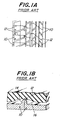
- one possible solution may be to arrange the boundary portion 12 of the adjacent fitting pieces 10 at a location corresponding to a groove portion of the product tire or to a protrusion 14 on the inner surface of the mold, as shown in Fig. 1B.
- a structure makes it difficult to properly discharge air from the inside space of the mold. Rather, air tends to remain at a portion of the mold space which corresponds to the junction of a land portion and an adjacent groove portion of the product tire.
- the residual air within the mold often forms so-called “sags” and "bubbles” along the edge of the land portion of the product tire, and significantly deteriorates the appearance of the tire.
- a "backbone” type mold which is disclosed, for example, in Japanese Patent Examined Publication No. 1-51,324.
- This type of curing mold includes an annular mold main body with a basic inner surface configuration corresponding to the land portion of a product tire in at least a tread portion thereof, and a plurality of projections corresponding to the groove portions of the product tire which are detachably secured to the main body for realizing a mold of a desired inner surface configuration.
- the present invention has been conceived by taking the abovementioned problems into consideration, and it is an object of the present invention to provide a novel curing mold which makes it possible to realize an excellent appearance and improved accuracy and uniformity of product tires, and to readily respond to change in tire design and facilitate maintenance of the mold.
- a curing mold for pneumatic tires comprising a plurality of segments which are detachably aligned with each other in a direction of the mold corresponding to a circumferential direction of a product tire.
- Each segment has an inner circumferential surface portion which is complementary in shape to land and groove portions in a tread region of the tire.
- Each segment comprises a plurality of fitting pieces and a supporting block for supporting the fitting pieces so as to form a part of the inner circumferential surface portion.
- Each fitting pieces comprises a projection which is complementary in shape to part of the groove portion.
- Both ends of the fitting piece are fixing portions at the inner circumferential surface portion of the segment, for fixedly securing the fitting piece to the supporting block. At least one of the fixing portions is complementary in shape to part of the land portion.
- Each supporting block has fitting grooves corresponding to the fixing portions of said fitting pieces. The fixing portions of each fitting piece is engaged in the fitting grooves of the block.
- each fitting piece is formed of a material having a thermal expansion coefficient which is higher than that of a material forming the supporting block.
- a method of manufacturing a curing mold for pneumatic tires comprising a plurality of segments which are detachably aligned with each other in a direction of the mold corresponding to a circumferential direction of a product tire, each segment having an inner circumferential surface portion which is complementary in shape to land and groove portions in a tread region of the tire, wherein the method comprises the steps of preparing a plurality of fitting pieces, each having a projection which is complementary in shape to part of the groove portion of the tire and fixing portions at both ends of the projection, at least one of which is complementary in shape to part of the land portion of the tire, preparing a supporting block having fitting grooves corresponding to the fixing portions of the fitting pieces in that side of the supporting block which forms part of the inner circumferential surface portion of the mold, and successively securing the fitting pieces to the supporting block by engaging the fixing portions of the fitting pieces into the fitting grooves of the supporting block, so as to form the segment.
- each fitting piece of the curing mold can be fixedly secured to the supporting block by engaging the fixing portion at both ends into the fitting grooves of the supporting block.
- the fitting pieces can fixedly secured to the supporting block without fastening means as required in the abovementioned prior art.
- each fitting piece (except for the fixing portion) is opposed to the supporting block with the surface which is arranged substantially in a region of the mold corresponding to the tread region of the product tire.
- a sufficient amount of non-vulcanized rubber can thus be filled into that portion of the mold which corresponds to the edge at the land portion of the product tire. This means that air is prevented from remaining in such a mold portion as was the case in the prior art, so that neither bubbles nor sags are generated in the corresponding portion of the product tire.
- the burrs are formed to extend approximately within a plane including the tread region of the product tire, namely in the groove portion of the tire.
- the appearance of the product tire in its tread region is less deteriorated as compared with the prior art tire in which burrs are formed to protrude radially outwardly from the tread region of the tire.
- the portion of the mold corresponding to the tread region of the product tire is directly formed by the supporting blocks having the inner surface shape corresponding to the tread region, it is possible to improve the uniformity of the mold in the circumferential direction by assembling the blocks in an annular arrangement and subjecting their inner surfaces to a machining into an substantially regular circle, with a lathe, for example.
- Fig. 2A one preferred embodiment of the curing mold according to the present invention, which is designated as a whole by reference numeral 20.
- the mold 20 has an inner surface configuration corresponding to land and groove portions of a product tire at least in a tread portion thereof.
- the mold 20 is composed of a plurality of segments 22 which are aligned and connected with each other in the circumferential direction of the mold into an annular configuration.
- each segment 22 is provided with a supporting block 24 and a plurality of fitting pieces 26 secured to the block 24.
- These supporting block 24 and fitting pieces 26 cooperate with each other to form inner circumferential surface portion of the mold 20 which is complementary in shape to the land and groove portions of the product tire in its tread portion.
- Fig. 2B shows only one fitting piece 26, this is merely for the sake of simplicity.
- one supporting block 24 is usually combined with a plurality of fitting pieces 26, e.g., seven or eight in number.
- the block 24 has an inside portion 28 forming part of the inner circumferential surface of the mold which is complementary to the tread portion of the product tire.
- the inside portion 28 is formed with a plurality of concave portions 30 which are complementary to the land portions at the ground contacting portion of the product tire.
- the concave portions 30 extend in the circumferential direction of the mold 20 to form circumferential land portions of the tire.
- the inside portion 28 of the block 24 has regions 32 corresponding to a tread center region of the product tire and its shoulder portions. These regions of the block 24 are formed with fitting grooves 34a, 34b to extend in the circumferential direction of the mold 20, respectively, so as to form further circumferential land portions of the tire.
- Each fitting piece 26 cooperates with the block 24 to form an inner circumferential surface portion of the mold which is complementary to the tread portion of the product tire.
- the inner surface of the fitting piece 26 is provided with ridges 36a, 36b which correspond to circumferential grooves of the tire, and further ridges 38a, 38b which, in turn, correspond to lateral grooves of the tire intersecting with the circumferential grooves.
- These ridges 36a, 36b, 38a, 38b jointly constitute an integral projection 40 which is a groove forming element of each segment 22. Both ends of the projection 40 are spaced in the width direction of the mold 20, and provided with fixing portions 42, 44 which are to be engaged into the fitting grooves 34a, 34b in the block 24, respectively.
- a further fixing portion 48 is provided for the projection 36b which is situated at an intermediate position between the both end fixing portions 42 and 44.
- the fitting grooves 34a, 34b of the block 24 are configured such that the groove 34a has a side wall on the side of the tread center region of the product tire, which is opposed to a side wall of the groove 34b on the side of the side wall region of the tire.
- These side walls of the grooves 34a, 34b are spaced from each other by a predetermined distance which increases radially outwardly of the mold 20 as seen in a radial cross-section of the product tire.
- Such a configuration of the grooves 34a, 34b permits the fitting pieces 26 to be successively fitted to the segment 22 from the side of the connecting surface 24a of the segment 22, as shown in Fig. 3B, and to prevent undesired radial movement or play of the fitting pieces 26 already fitted to the block 24.
- the projection 40 can be more positively secured to the block 24 as compared with the conventional arrangement wherein the projection 40 has an external form corresponding to the groove portions of the product tire and is directly secured to the block 24.
- At least one of the fixing portions 42, 44 is of a complementary shape with respect to the land portion of the product tire. This, in the present embodiment, is the case for the fixing portion 44 on the side of the shoulder region of the product tire.
- the projection 40 of the fitting piece 26 may have a fixing portion in the tread center region of the product tire, which is of a complementary shape with respect to the land portion of the tire, if necessary. Also, the fixing portions at both ends of the projection 40 may be of a similar complementary shape.
- the fitting pieces 26 may be secured to the block 24 in various ways, and the manner of securing the fitting pieces is not limited to that as in the abovementioned embodiment.
- the block 24 of segment 22 may include a separable wall portion in which the fitting groove 34b is formed.
- the fixing portions, 44 of the fitting piece 26 can be engaged into the relevant fitting grooves, 34b, with the wall portion separated from the block 24.
- the wall portion can then be integrally secured to the block 24 together with the fitting piece 26.
- a boundary portion 46 is formed along the edge of each fitting piece 26 secured to the block 24 of the segment 22, as schematically shown with a bold solid line.
- the boundary portion is formed between adjacent fitting pieces as shown in Fig. 3 by broken lines. This is because the prior art fitting piece, whose inner surface portion is complementary to the land and groove portions in the tread region of the product tire, is adjoined to a neighboring fitting piece for completing the entire mold inner surface.
- boundary portions function as passages for discharging air within a space between the mold and the green tire.
- a larger cross-sectional area or a longer peripheral length of the discharge passage serves to more effectively discharge the air from the mold.
- the boundary portion 46 of the curing mold according to the present invention is much longer than that of the conventional one shown by the broken line.
- the boundary portion shown by the broken line is positioned in the entire area of the mold region corresponding to the tread region of the product tire, so that outwardly protruding burrs tend to be formed on the tread region of the product tire to significantly deteriorate its appearance.
- a substantial portion of the tread region is directly formed by the block 24 of a complementary shape, making it possible to prevent or at least minimize formation of burrs in the tread region of the product tire.
- segment 22 of the curing mold according to the present invention is composed of the blocks 24 each defining the inner surface shape of the mold except for the projection 40 inclusive of the fixing portions, and having the complementary shape with respect to the tread region of the product tire. It is thus possible to improve the out-of-roundness in the tread region of the product tire.
- Both end fixing portions of the projection 40 are secured into the fitting grooves of the block 24 of the shape which corresponds to the outer shape of the tire to be molded. Further, the ridges 38a, 38b of the projection 40 are supported by the block 24 which is complementary to the outer shape of the product tire. Consequently, the boundary portion is also formed between the block 24 and the ridges 38a, 38b.
- non-vulcanized tread rubber can be sufficiently filled up to the portion of the mold corresponding to the edge of the land portion of the product tire. On this occasion, there may be instances wherein burrs are formed due to possible extrusion of rubber through the boundary portion.
- the resultant burrs extend in parallel with a plane including the tread region of the product tire and protrude toward inside of the groove of the product tire.
- burrs are less influential on the appearance of the product tire, as compared with the burrs which are formed by conventional mold to protrude radially outwardly from the tread region of the tire.
- the connecting surface of each fitting piece is an opposing surface portion at the fixing portion of mutually adjacent fitting pieces so that only these surface portions require machining as the connecting surface.
- the fitting piece 26 is made of a material with a thermal expansion coefficient which is higher than that of the material forming the block 24 to which these fitting pieces 26 are attached. Owing to such a construction, during the vulcanization of the green tire, the fitting piece 26 undergoes an expansion relative to the block 24, with the both ends of the fitting piece 26 restrained by the fixing portions with respect to the block 24. Further, the fitting piece 26 has a curvature with a center of curvature positioned inward of the mold. Thus, the projection 40 is curved during the vulcanization of the green tire, making the side opposing to the block 24 to be outside. In other words, the projection 40 is tightly urged against the block 24 so that the projection 40 is effectively prevented from separation from the inner surface of the mold during the vulcanization, as was the case in the prior art curing mold.
- the fitting pieces 26 are prepared each having an inner circumferential surface which is complementary to a part of the groove portion of the tread portion of the product tire, so that the outer surface of the green tire can be brought into a pressure contact during the vulcanization.
- the fitting piece 26 is formed with the fixing portions on both ends thereof, so that at least one of the fixing portions is complementary to a part of the land portion in at least the tread region of the product tire.
- the block 24 for integrally supporting these fitting pieces 26 are prepared each having an inner circumferential surface which is complementary to the tread region of the product tire, and further having the fitting grooves in which the fixing portions of the fitting piece 26 can be engaged. Then, each fitting piece 26 is mutually adjoined with each other, with the fixing portions thereof engaged into the fitting grooves of the block 24, so as to provide a segment 22 of the curing mold.
- the effective length L1 of the boundary portion for the discharge of air from the inside of the curing mold can be increased by two and half times, the length L2 of the boundary portion appearing in the tread region of the product tire can be reduced by about one third, the machining hour required for the fitting piece can be reduced by one half, and the out-of-roundness can be reduced by one half.
- the present invention serves to realize an improved curing mold which provides an excellent appearance and improved uniformity and accuracy of the product tires, which facilitates the manufacture and maintenance of the mold, and which is easy to respond to changes in tire design.
- each projection may be provided with the fixing portions on both ends, or common fixing portions may be provided for a plurality of spaced projections on their both ends, or a common fixing portion may be provided for a plurality of spaced projections on their intermediate regions.
Landscapes
- Engineering & Computer Science (AREA)
- Mechanical Engineering (AREA)
- Moulds For Moulding Plastics Or The Like (AREA)
- Heating, Cooling, Or Curing Plastics Or The Like In General (AREA)
Abstract
Description
- The present invention relates to a curing mold for vulcanizing green tires and thereby manufacturing pneumatic tires.
- Conventionally, various types of curing mold for manufacturing pneumatic tires are known. For example, a so-called insert segment type curing mold includes a plurality of fitting pieces each having an inner surface with concave or convex portions corresponding to land or groove portions of a product tire at least in its tread portion. A set of fitting pieces are mutually adjoined with each other and secured to a supporting member to form a segment, and a set of segments are mutually adjoined with each other into an annular assembly with a predetermined inner surface configuration.
- It is generally necessary during the vulcanization process to tightly urge a green tire against the inner surface of the mold by means of an expansible bladder. Thus, air within a space between the outer surface of the green tire and the inner surface of the mold has to be discharged via
boundary portions 12 betweenadjacent fitting pieces boundary portions 12. Consequently, the insert segment type curing mold suffers from a problem that undesirable burrs tend to be formed at the land portion of the product tire inclusive of the ground contact portion. Such burrs protrude radially outwardly of the product tire and significantly deteriorate the appearance of the tire. - For preventing formation of burrs at the land portion of the product tire, one possible solution may be to arrange the
boundary portion 12 of theadjacent fitting pieces 10 at a location corresponding to a groove portion of the product tire or to aprotrusion 14 on the inner surface of the mold, as shown in Fig. 1B. However, such a structure makes it difficult to properly discharge air from the inside space of the mold. Rather, air tends to remain at a portion of the mold space which corresponds to the junction of a land portion and an adjacent groove portion of the product tire. The residual air within the mold often forms so-called "sags" and "bubbles" along the edge of the land portion of the product tire, and significantly deteriorates the appearance of the tire. - For overcoming the abovementioned drawbacks, another type of curing mold is known such as a "backbone" type mold which is disclosed, for example, in Japanese Patent Examined Publication No. 1-51,324. This type of curing mold includes an annular mold main body with a basic inner surface configuration corresponding to the land portion of a product tire in at least a tread portion thereof, and a plurality of projections corresponding to the groove portions of the product tire which are detachably secured to the main body for realizing a mold of a desired inner surface configuration.
- Such an arrangement of "backbone" type curing mold proved to be advantageous in that air within the mold can be discharged from the gap between the main body and the projections, corresponding to the edge of the land portion of a product tire, without forming burrs at the ground contacting portion of the product tire. However, this type of curing mold suffers from different disadvantages as follows. At the outset, fastening operation for securing the projections to the mold main body with a number of bolts or the like is time-consuming and troublesome. It is also difficult to uniformly and accurately secure the projections to the mold main body for improving the product quality in terms of uniformity and accuracy. Moreover, for ensuring a stable discharge of air from the mold through the gap between the mold main body and the projections, it is necessary to periodically separate the projections from the mold main body so that not only the assembly of the curing mold, but also its maintenance is troublesome.
- Apart from the above, there may be instances wherein it is desirable to modify existing curing mold in view of minor changes in design of the tread pattern. However, known curing molds are not always suitable for such modification, and it has been a general practice to prepare entirely new molds for respective tread patterns even in the case of minor changes.
- The present invention has been conceived by taking the abovementioned problems into consideration, and it is an object of the present invention to provide a novel curing mold which makes it possible to realize an excellent appearance and improved accuracy and uniformity of product tires, and to readily respond to change in tire design and facilitate maintenance of the mold.
- In order to achieve the abovementioned object, according to one aspect of the present invention, there is provided a curing mold for pneumatic tires, comprising a plurality of segments which are detachably aligned with each other in a direction of the mold corresponding to a circumferential direction of a product tire. Each segment has an inner circumferential surface portion which is complementary in shape to land and groove portions in a tread region of the tire. Each segment comprises a plurality of fitting pieces and a supporting block for supporting the fitting pieces so as to form a part of the inner circumferential surface portion. Each fitting pieces comprises a projection which is complementary in shape to part of the groove portion. Both ends of the fitting piece are fixing portions at the inner circumferential surface portion of the segment, for fixedly securing the fitting piece to the supporting block. At least one of the fixing portions is complementary in shape to part of the land portion. Each supporting block has fitting grooves corresponding to the fixing portions of said fitting pieces.
The fixing portions of each fitting piece is engaged in the fitting grooves of the block. - Preferably, each fitting piece is formed of a material having a thermal expansion coefficient which is higher than that of a material forming the supporting block.
- According to another aspect of the present invention, there is provided a method of manufacturing a curing mold for pneumatic tires, comprising a plurality of segments which are detachably aligned with each other in a direction of the mold corresponding to a circumferential direction of a product tire, each segment having an inner circumferential surface portion which is complementary in shape to land and groove portions in a tread region of the tire, wherein the method comprises the steps of preparing a plurality of fitting pieces, each having a projection which is complementary in shape to part of the groove portion of the tire and fixing portions at both ends of the projection, at least one of which is complementary in shape to part of the land portion of the tire, preparing a supporting block having fitting grooves corresponding to the fixing portions of the fitting pieces in that side of the supporting block which forms part of the inner circumferential surface portion of the mold, and successively securing the fitting pieces to the supporting block by engaging the fixing portions of the fitting pieces into the fitting grooves of the supporting block, so as to form the segment.
- According to the present invention, each fitting piece of the curing mold can be fixedly secured to the supporting block by engaging the fixing portion at both ends into the fitting grooves of the supporting block. Thus, the fitting pieces can fixedly secured to the supporting block without fastening means as required in the abovementioned prior art. In addition, it is possible to increase the length of the boundary portion of the projection including the periphery of the fixing portion and the block, that is the length of the portion effective for the discharge of air in the space defined by and between the mold and the green tire, so that it is possible to positively discharge the air from the inside space of the mold in a reliable manner. Furthermore, each fitting piece (except for the fixing portion) is opposed to the supporting block with the surface which is arranged substantially in a region of the mold corresponding to the tread region of the product tire. A sufficient amount of non-vulcanized rubber can thus be filled into that portion of the mold which corresponds to the edge at the land portion of the product tire. This means that air is prevented from remaining in such a mold portion as was the case in the prior art, so that neither bubbles nor sags are generated in the corresponding portion of the product tire.
- Moreover, even when burrs are formed due to a possible extrusion of non-vulcanized rubber from the boundary portion of the mold, the burrs are formed to extend approximately within a plane including the tread region of the product tire, namely in the groove portion of the tire. Thus, the appearance of the product tire in its tread region is less deteriorated as compared with the prior art tire in which burrs are formed to protrude radially outwardly from the tread region of the tire. Since, furthermore, the portion of the mold corresponding to the tread region of the product tire is directly formed by the supporting blocks having the inner surface shape corresponding to the tread region, it is possible to improve the uniformity of the mold in the circumferential direction by assembling the blocks in an annular arrangement and subjecting their inner surfaces to a machining into an substantially regular circle, with a lathe, for example.
- The present invention will now be described hereinafter in greater detail with reference to the accompanying drawings, in which:-
- Figs. 1A and 1B are explanatory views showing the conventional curing mold as explained above, which is used to vulcanize a green tire for manufacturing a pneumatic tire;
- Fig. 2A is an explanatory view showing the curing mold according to the present invention including a plurality of segments;
- Fig. 2B is a perspective view showing the segment in an enlarged scale;
- Figs. 3A to 3C are explanatory views showing the manner of assembly of the fitting pieces to the block; and
- Fig. 4 is an explanatory view showing the boundary portion of the segments.
- There is shown in Fig. 2A one preferred embodiment of the curing mold according to the present invention, which is designated as a whole by
reference numeral 20. For allowing a vulcanization of a green tire, themold 20 has an inner surface configuration corresponding to land and groove portions of a product tire at least in a tread portion thereof. Themold 20 is composed of a plurality ofsegments 22 which are aligned and connected with each other in the circumferential direction of the mold into an annular configuration. - As clearly shown in Fig. 2B, each
segment 22 is provided with a supportingblock 24 and a plurality offitting pieces 26 secured to theblock 24. These supportingblock 24 and fittingpieces 26 cooperate with each other to form inner circumferential surface portion of themold 20 which is complementary in shape to the land and groove portions of the product tire in its tread portion. While Fig. 2B shows only onefitting piece 26, this is merely for the sake of simplicity. As a matter of fact, one supportingblock 24 is usually combined with a plurality offitting pieces 26, e.g., seven or eight in number. - The
block 24 has aninside portion 28 forming part of the inner circumferential surface of the mold which is complementary to the tread portion of the product tire. Theinside portion 28 is formed with a plurality ofconcave portions 30 which are complementary to the land portions at the ground contacting portion of the product tire. In the embodiment illustrated, theconcave portions 30 extend in the circumferential direction of themold 20 to form circumferential land portions of the tire. Furthermore, theinside portion 28 of theblock 24 hasregions 32 corresponding to a tread center region of the product tire and its shoulder portions. These regions of theblock 24 are formed withfitting grooves mold 20, respectively, so as to form further circumferential land portions of the tire. - Each
fitting piece 26 cooperates with theblock 24 to form an inner circumferential surface portion of the mold which is complementary to the tread portion of the product tire. In the illustrated embodiment, the inner surface of thefitting piece 26 is provided withridges further ridges ridges integral projection 40 which is a groove forming element of eachsegment 22. Both ends of theprojection 40 are spaced in the width direction of themold 20, and provided with fixingportions fitting grooves block 24, respectively. Engagement of the fixingportions fitting grooves fitting piece 26 to be integrally secured to theblock 24. In the present embodiment, for more stably securing thefitting piece 26 to theblock 24, a further fixingportion 48 is provided for theprojection 36b which is situated at an intermediate position between the bothend fixing portions - As schematically shown in Fig. 3, the
fitting grooves block 24 are configured such that thegroove 34a has a side wall on the side of the tread center region of the product tire, which is opposed to a side wall of thegroove 34b on the side of the side wall region of the tire. These side walls of thegrooves mold 20 as seen in a radial cross-section of the product tire. Such a configuration of thegrooves fitting pieces 26 to be successively fitted to thesegment 22 from the side of the connectingsurface 24a of thesegment 22, as shown in Fig. 3B, and to prevent undesired radial movement or play of thefitting pieces 26 already fitted to theblock 24. - Due to the provision of the fixing portions at the end portions, the
projection 40 can be more positively secured to theblock 24 as compared with the conventional arrangement wherein theprojection 40 has an external form corresponding to the groove portions of the product tire and is directly secured to theblock 24. At least one of the fixingportions portion 44 on the side of the shoulder region of the product tire. With such an arrangement, the junction between thefitting piece 26 and theblock 24 can be situated at a location where undesired bubbles and sag would otherwise tend to be generated during vulcanization of the tire. In other words, air within themold 20 can be discharged from themold 20 in a reliable manner, without generating the bubbles and sag. - The
projection 40 of thefitting piece 26 may have a fixing portion in the tread center region of the product tire, which is of a complementary shape with respect to the land portion of the tire, if necessary. Also, the fixing portions at both ends of theprojection 40 may be of a similar complementary shape. - The
fitting pieces 26 may be secured to theblock 24 in various ways, and the manner of securing the fitting pieces is not limited to that as in the abovementioned embodiment. As represented by broken lines in Fig. 3A-3C, for example, theblock 24 ofsegment 22 may include a separable wall portion in which thefitting groove 34b is formed. In this case, the fixing portions, 44 of thefitting piece 26 can be engaged into the relevant fitting grooves, 34b, with the wall portion separated from theblock 24. The wall portion can then be integrally secured to theblock 24 together with thefitting piece 26. By securing a plurality offitting pieces 26 to theblock 24 in this way, asegment 22 can be obtained which is partly shown in Fig. 3C and also indicated by hatch lines in Fig. 4. - In the case of such a
segment 22, aboundary portion 46 is formed along the edge of eachfitting piece 26 secured to theblock 24 of thesegment 22, as schematically shown with a bold solid line. On the contrary, in the conventional curing mold such as that shown in Figs. 1A and 1B, the boundary portion is formed between adjacent fitting pieces as shown in Fig. 3 by broken lines. This is because the prior art fitting piece, whose inner surface portion is complementary to the land and groove portions in the tread region of the product tire, is adjoined to a neighboring fitting piece for completing the entire mold inner surface. - Such boundary portions function as passages for discharging air within a space between the mold and the green tire. A larger cross-sectional area or a longer peripheral length of the discharge passage serves to more effectively discharge the air from the mold. In this connection, the
boundary portion 46 of the curing mold according to the present invention, as shown by the bold solid line in Fig. 4, is much longer than that of the conventional one shown by the broken line. - Furthermore, in the conventional curing mold, the boundary portion shown by the broken line is positioned in the entire area of the mold region corresponding to the tread region of the product tire, so that outwardly protruding burrs tend to be formed on the tread region of the product tire to significantly deteriorate its appearance. On the contrary, according to the present invention, a substantial portion of the tread region is directly formed by the
block 24 of a complementary shape, making it possible to prevent or at least minimize formation of burrs in the tread region of the product tire. - Further, the
segment 22 of the curing mold according to the present invention is composed of theblocks 24 each defining the inner surface shape of the mold except for theprojection 40 inclusive of the fixing portions, and having the complementary shape with respect to the tread region of the product tire. It is thus possible to improve the out-of-roundness in the tread region of the product tire. - Both end fixing portions of the
projection 40 are secured into the fitting grooves of theblock 24 of the shape which corresponds to the outer shape of the tire to be molded. Further, theridges projection 40 are supported by theblock 24 which is complementary to the outer shape of the product tire. Consequently, the boundary portion is also formed between theblock 24 and theridges - Further, in the curing mold according to the present invention, the connecting surface of each fitting piece is an opposing surface portion at the fixing portion of mutually adjacent fitting pieces so that only these surface portions require machining as the connecting surface. This is particularly advantageous in that the production of the mold can be facilitated and the accuracy of the mold can be readily improved, in contrast to the conventional one wherein machining must be carried out with respect to the connecting surface of each fitting piece substantially over the entire circumference, as shown in Fig. 4 by the broken line.
- In another embodiment according to the present invention, the
fitting piece 26 is made of a material with a thermal expansion coefficient which is higher than that of the material forming theblock 24 to which thesefitting pieces 26 are attached. Owing to such a construction, during the vulcanization of the green tire, thefitting piece 26 undergoes an expansion relative to theblock 24, with the both ends of thefitting piece 26 restrained by the fixing portions with respect to theblock 24. Further, thefitting piece 26 has a curvature with a center of curvature positioned inward of the mold. Thus, theprojection 40 is curved during the vulcanization of the green tire, making the side opposing to theblock 24 to be outside. In other words, theprojection 40 is tightly urged against theblock 24 so that theprojection 40 is effectively prevented from separation from the inner surface of the mold during the vulcanization, as was the case in the prior art curing mold. - It will be readily appreciated that the curing mold according to the present invention can be produced in the following manner:
First of all, thefitting pieces 26 are prepared each having an inner circumferential surface which is complementary to a part of the groove portion of the tread portion of the product tire, so that the outer surface of the green tire can be brought into a pressure contact during the vulcanization. Thefitting piece 26 is formed with the fixing portions on both ends thereof, so that at least one of the fixing portions is complementary to a part of the land portion in at least the tread region of the product tire. On the other hand, theblock 24 for integrally supporting thesefitting pieces 26 are prepared each having an inner circumferential surface which is complementary to the tread region of the product tire, and further having the fitting grooves in which the fixing portions of thefitting piece 26 can be engaged. Then, eachfitting piece 26 is mutually adjoined with each other, with the fixing portions thereof engaged into the fitting grooves of theblock 24, so as to provide asegment 22 of the curing mold. - For examining the superiority of the present invention, green tires were vulcanized and molded using the curing mold according to the present invention and a prior art mold of the insert segment type. Comparisons were made with reference to the length of the boundary portion effective for discharge of air from the mold (L₁), the length of the boundary portion appearing in the tread region of the product tire (L₂), the machining hour required for machining the fitting piece connecting surface, and the out-of-roundness of the ground contacting portion of the product tire. The results of the comparisons are shown in the following table with indices which are 100 for each item of the insert segment type. Except for the length L₁ of the boundary portion, smaller indices represent improvement achieved by the present invention.

- The foregoing table clearly shows that, in accordance with the present invention, the effective length L₁ of the boundary portion for the discharge of air from the inside of the curing mold can be increased by two and half times, the length L₂ of the boundary portion appearing in the tread region of the product tire can be reduced by about one third, the machining hour required for the fitting piece can be reduced by one half, and the out-of-roundness can be reduced by one half.
- Thus, the present invention serves to realize an improved curing mold which provides an excellent appearance and improved uniformity and accuracy of the product tires, which facilitates the manufacture and maintenance of the mold, and which is easy to respond to changes in tire design.
- The present invention is not limited to the abovementioned embodiments, and various modifications may be made without departing from the scope of claims.
- For example, each projection may be provided with the fixing portions on both ends, or common fixing portions may be provided for a plurality of spaced projections on their both ends, or a common fixing portion may be provided for a plurality of spaced projections on their intermediate regions.
Claims (3)
- A curing mold (20) for pneumatic tires, comprising a plurality of segments (22) which are detachably alignable with each other in a direction of the mold corresponding to a circumferential direction of a product tire, each segment (22) having an inner circumferential surface portion which is complementary in shape to land and groove portions in a tread region of the tire, said segments each comprising a plurality of fitting pieces (26) and a supporting block (24) for supporting the fitting pieces so as to form a part of said inner circumferential surface portion, said fitting pieces each comprising a projection (40) which is complementary in shape to part of said groove portion, with both ends of each fitting piece being fixing portions (42,44) at said inner circumferential surface portion of said segment (22), for fixedly securing the fitting piece (26) to the supporting block (24), at least one of said fixing portions being complementary in shape to part of said land portion, said supporting block having fitting grooves (34a,34b) corresponding to the fixing portions (42,44) of said fitting pieces, the fixing portions of each fitting piece being engaged in the fitting grooves of the supporting block.
- A curing mold as claimed in claim 1, characterized in that each fitting piece (26) is formed of a material having a thermal expansion coefficient which is higher than that of a material forming the supporting block (24).
- A method of manufacturing a curing mold (20) for pneumatic tires, which curing mold comprises a plurality of segments (22) which are detachably alignable with each other in a direction of the mold corresponding to a circumferential direction of a product tire, each segment (22) having an inner circumferential surface portion which is complementary in shape to land and groove portions in a tread region of the tire, wherein said method comprises the steps of:
preparing or taking a plurality of fitting pieces (26), each having a projection (40) which is complementary in shape to part of said groove portion of the tire and fixing portions (42, 44) at both ends of the projection, at least one of which is complementary in shape to part of said land portion of the tire;
preparing or taking a supporting block (24) having fitting grooves (34a, 34b) corresponding to the fixing portions (42, 44) of the fitting pieces (26) in that side of the supporting block which forms part of said inner circumferential surface portion of the mold; and
successively securing the fitting pieces (26) to the supporting block (24) by engaging the fixing portions (42, 44) of the fitting pieces into the fitting grooves (34a, 34b) of the supporting block, so as to form said segment.
Applications Claiming Priority (2)
| Application Number | Priority Date | Filing Date | Title |
|---|---|---|---|
| JP198350/91 | 1991-07-15 | ||
| JP3198350A JPH0516144A (en) | 1991-07-15 | 1991-07-15 | Tire vulcanizing mold and manufacture thereof |
Publications (2)
| Publication Number | Publication Date |
|---|---|
| EP0523958A1 true EP0523958A1 (en) | 1993-01-20 |
| EP0523958B1 EP0523958B1 (en) | 1996-05-22 |
Family
ID=16389652
Family Applications (1)
| Application Number | Title | Priority Date | Filing Date |
|---|---|---|---|
| EP92306442A Expired - Lifetime EP0523958B1 (en) | 1991-07-15 | 1992-07-14 | Curing mold for pneumatic tires |
Country Status (5)
| Country | Link |
|---|---|
| US (1) | US5340294A (en) |
| EP (1) | EP0523958B1 (en) |
| JP (1) | JPH0516144A (en) |
| DE (1) | DE69210897T2 (en) |
| ES (1) | ES2090522T3 (en) |
Cited By (6)
| Publication number | Priority date | Publication date | Assignee | Title |
|---|---|---|---|---|
| FR2722729A1 (en) * | 1994-07-20 | 1996-01-26 | Hutchinson | Tyre moulding and vulcanisation useful esp. for off road vehicles |
| FR2939712A1 (en) * | 2008-12-17 | 2010-06-18 | Michelin Soc Tech | MOLD TRIM COMPRISING A SACRIFICIAL LINK ELEMENT |
| FR2939714A1 (en) * | 2008-12-17 | 2010-06-18 | Michelin Soc Tech | TRIM ASSEMBLY ON SKIN. |
| FR2939713A1 (en) * | 2008-12-17 | 2010-06-18 | Michelin Soc Tech | FITTING ELEMENT COMPRISING A SHELL AND A CORE |
| FR2940166A1 (en) * | 2008-12-24 | 2010-06-25 | Michelin Soc Tech | METHOD FOR MANUFACTURING A TRIM MEMBER AND A SUPPORT MEMBER FOR A PNEUMATIC MOLD |
| WO2021254653A1 (en) * | 2020-06-17 | 2021-12-23 | Continental Reifen Deutschland Gmbh | Method for producing a mold segment component, mold segment component, vulcanization mold, and pneumatic vehicle tire |
Families Citing this family (19)
| Publication number | Priority date | Publication date | Assignee | Title |
|---|---|---|---|---|
| FR2729329A1 (en) * | 1995-01-18 | 1996-07-19 | Michelin & Cie | PROCESS AND DEVICE FOR PRODUCING AT LEAST ONE TIRE MOLD COMPRISING AT LEAST ONE MOLDING ELEMENT WITH A NON-DEMOLDABLE PATTERN |
| US5798124A (en) * | 1996-01-17 | 1998-08-25 | The Goodyear Tire & Rubber Company | Tire tread element mold chamfer to modify RCF and/or RSAT using the existing mold |
| JP3606411B2 (en) * | 1996-07-10 | 2005-01-05 | 株式会社ブリヂストン | Tire vulcanization mold and manufacturing method thereof |
| FR2759626A1 (en) * | 1997-02-19 | 1998-08-21 | Sedepro | TIRE MOLD |
| FR2772663A1 (en) * | 1997-12-24 | 1999-06-25 | Michelin & Cie | METHOD AND MOLDING ELEMENT FOR MOLDING A CUT IN A TIRE TRUCK |
| KR100388724B1 (en) * | 2001-01-08 | 2003-06-25 | 금호산업주식회사 | Semi-Segmented 2-Piece Mold of Tire Curing Machine |
| JP4972425B2 (en) * | 2007-02-13 | 2012-07-11 | 東洋ゴム工業株式会社 | Tire vulcanization mold and tire manufacturing method |
| US7717691B2 (en) * | 2007-06-05 | 2010-05-18 | Bridgestone Americas Tire Operations, Llc | Tire mold with vent inlet disposed under mold rib |
| KR101611844B1 (en) * | 2008-10-23 | 2016-04-12 | 후지 세이코 가부시키가이샤 | Tire vulcanization forming mold |
| US8731871B2 (en) | 2010-09-22 | 2014-05-20 | Bridgestone Americas Tire Operations, Llc | Tire mold design method to minimize unique annular mold parts |
| JP5647646B2 (en) * | 2012-06-08 | 2015-01-07 | 住友ゴム工業株式会社 | Tire vulcanization mold and pneumatic tire manufacturing method |
| JP5534483B1 (en) | 2013-01-24 | 2014-07-02 | 株式会社ブリヂストン | Sector mold and manufacturing method |
| JP5579292B1 (en) * | 2013-02-25 | 2014-08-27 | 株式会社ブリヂストン | Tire vulcanization mold manufacturing method and tire vulcanization mold |
| FR3014351B1 (en) * | 2013-12-06 | 2016-06-03 | Michelin & Cie | METHOD OF MANUFACTURING A MOLDING ELEMENT OF A MOLD FOR THE VULCANIZATION OF A TIRE |
| WO2016036340A1 (en) * | 2014-09-01 | 2016-03-10 | Compagnie Generale Des Etablissements Michelin | Replaceable center rib for a tire tread dual mold |
| US20190217563A1 (en) * | 2016-09-07 | 2019-07-18 | Bridgestone Americas Tire Operations, Llc | Tread pattern mold insert |
| US20180207996A1 (en) * | 2017-01-24 | 2018-07-26 | The Goodyear Tire & Rubber Company | Tread wear indicator |
| EP3600861B1 (en) * | 2017-03-31 | 2022-03-02 | Compagnie Générale des Etablissements Michelin | Tire mold with interchangeable element having removably attachable lamelle |
| JP6993262B2 (en) * | 2018-02-22 | 2022-02-04 | 株式会社ブリヂストン | Tire molding dies, tire molding dies manufacturing methods and tires |
Citations (5)
| Publication number | Priority date | Publication date | Assignee | Title |
|---|---|---|---|---|
| US1880430A (en) * | 1931-02-14 | 1932-10-04 | Firestone Tire & Rubber Co | Tire mold |
| FR1575605A (en) * | 1968-03-05 | 1969-07-25 | ||
| FR2541624A1 (en) * | 1983-02-26 | 1984-08-31 | Herbert Maschbau Kg | Mould for accurately circular tyre |
| US4708609A (en) * | 1984-03-22 | 1987-11-24 | Bridgestone Corporation | Tire manufacturing mold |
| EP0451832A2 (en) * | 1990-04-13 | 1991-10-16 | PIRELLI COORDINAMENTO PNEUMATICI S.p.A. | A mold and method of tyre curing and method for mold manufacturing |
Family Cites Families (5)
| Publication number | Priority date | Publication date | Assignee | Title |
|---|---|---|---|---|
| US3341933A (en) * | 1962-10-04 | 1967-09-19 | Mcphaden Bruce | Method of making a matrix for molds |
| US3697211A (en) * | 1970-08-13 | 1972-10-10 | Dow Chemical Co | Extrusion die |
| US4553918A (en) * | 1983-05-30 | 1985-11-19 | Bridgestone Corporation | Tire molding mold |
| JPS60198210A (en) * | 1984-03-22 | 1985-10-07 | Bridgestone Corp | Tire molding die and preparation thereof |
| JPS6451324A (en) * | 1987-08-21 | 1989-02-27 | Matsushita Electric Ind Co Ltd | Production of oxide superconducting material |
-
1991
- 1991-07-15 JP JP3198350A patent/JPH0516144A/en active Pending
-
1992
- 1992-07-10 US US07/911,585 patent/US5340294A/en not_active Expired - Fee Related
- 1992-07-14 EP EP92306442A patent/EP0523958B1/en not_active Expired - Lifetime
- 1992-07-14 DE DE69210897T patent/DE69210897T2/en not_active Expired - Fee Related
- 1992-07-14 ES ES92306442T patent/ES2090522T3/en not_active Expired - Lifetime
Patent Citations (5)
| Publication number | Priority date | Publication date | Assignee | Title |
|---|---|---|---|---|
| US1880430A (en) * | 1931-02-14 | 1932-10-04 | Firestone Tire & Rubber Co | Tire mold |
| FR1575605A (en) * | 1968-03-05 | 1969-07-25 | ||
| FR2541624A1 (en) * | 1983-02-26 | 1984-08-31 | Herbert Maschbau Kg | Mould for accurately circular tyre |
| US4708609A (en) * | 1984-03-22 | 1987-11-24 | Bridgestone Corporation | Tire manufacturing mold |
| EP0451832A2 (en) * | 1990-04-13 | 1991-10-16 | PIRELLI COORDINAMENTO PNEUMATICI S.p.A. | A mold and method of tyre curing and method for mold manufacturing |
Cited By (19)
| Publication number | Priority date | Publication date | Assignee | Title |
|---|---|---|---|---|
| FR2722729A1 (en) * | 1994-07-20 | 1996-01-26 | Hutchinson | Tyre moulding and vulcanisation useful esp. for off road vehicles |
| WO2010076503A1 (en) | 2008-12-17 | 2010-07-08 | Societe De Technologie Michelin | Moulding element for a tyre mould, including a shell and a core |
| FR2939714A1 (en) * | 2008-12-17 | 2010-06-18 | Michelin Soc Tech | TRIM ASSEMBLY ON SKIN. |
| FR2939713A1 (en) * | 2008-12-17 | 2010-06-18 | Michelin Soc Tech | FITTING ELEMENT COMPRISING A SHELL AND A CORE |
| FR2939712A1 (en) * | 2008-12-17 | 2010-06-18 | Michelin Soc Tech | MOLD TRIM COMPRISING A SACRIFICIAL LINK ELEMENT |
| CN102256778B (en) * | 2008-12-17 | 2016-05-18 | 米其林企业总公司 | For the liner assembly on the top layer of tyre vulcanized mould |
| US8449278B2 (en) | 2008-12-17 | 2013-05-28 | Compagnie Generale Des Etablissements Michelin | Mould lining comprising a sacrificial connecting element |
| WO2010076504A1 (en) | 2008-12-17 | 2010-07-08 | Societe De Technologie Michelin | Lining assembly on a skin for a tyre vulcanization mould |
| WO2010076502A1 (en) | 2008-12-17 | 2010-07-08 | Societe De Technologie Michelin | Lining assembly on a skin for a tyre vulcanization mould |
| CN102256777B (en) * | 2008-12-17 | 2014-07-09 | 米其林企业总公司 | Moulding element for a tyre mould, including a shell and a core |
| CN102256777A (en) * | 2008-12-17 | 2011-11-23 | 米其林技术公司 | Moulding element for a tyre mould, including a shell and a core |
| CN102256778A (en) * | 2008-12-17 | 2011-11-23 | 米其林技术公司 | Lining assembly on a skin for a tyre vulcanization mould |
| US8512020B2 (en) | 2008-12-17 | 2013-08-20 | Compagnie Generale Des Etablissements Michelin | Lining element comprising a shell and a core |
| FR2940166A1 (en) * | 2008-12-24 | 2010-06-25 | Michelin Soc Tech | METHOD FOR MANUFACTURING A TRIM MEMBER AND A SUPPORT MEMBER FOR A PNEUMATIC MOLD |
| CN102264493A (en) * | 2008-12-24 | 2011-11-30 | 米其林技术公司 | Method of manufacturing a cover element and a support element which are intended for a tyre mould |
| US8614405B2 (en) | 2008-12-24 | 2013-12-24 | Compagnie Generale Des Etablissements Michelin | Method of manufacturing a lining element |
| WO2010072960A3 (en) * | 2008-12-24 | 2010-09-30 | Societe De Technologie Michelin | Method of manufacturing a cover element and a support element which are intended for a tyre mould |
| WO2010072960A2 (en) | 2008-12-24 | 2010-07-01 | Societe De Technologie Michelin | Method of manufacturing a cover element and a support element which are intended for a tyre mould |
| WO2021254653A1 (en) * | 2020-06-17 | 2021-12-23 | Continental Reifen Deutschland Gmbh | Method for producing a mold segment component, mold segment component, vulcanization mold, and pneumatic vehicle tire |
Also Published As
| Publication number | Publication date |
|---|---|
| ES2090522T3 (en) | 1996-10-16 |
| JPH0516144A (en) | 1993-01-26 |
| US5340294A (en) | 1994-08-23 |
| EP0523958B1 (en) | 1996-05-22 |
| DE69210897D1 (en) | 1996-06-27 |
| DE69210897T2 (en) | 1996-11-28 |
Similar Documents
| Publication | Publication Date | Title |
|---|---|---|
| US5340294A (en) | Circumferentially aligned detachable segmented curing mold for pneumatic tires and method of manufacturing same | |
| US4895692A (en) | Mold for the molding and vulcanizing of a rubber tire | |
| US5769976A (en) | Pneumatic tire and method of making the same | |
| US7670124B2 (en) | Metal mold for vulcanizing tire treads | |
| US4305446A (en) | Cast tire and method of manufacture | |
| US4865532A (en) | Apparatus for vulcanizing pneumatic vehicle tires | |
| US10870248B2 (en) | Non-symmetrical tread ring parting line mold | |
| JP2005533685A (en) | Split tire mold to reduce flash | |
| US4992035A (en) | Vehicle tire mold | |
| US6387311B1 (en) | Manufacture of a support | |
| US2484620A (en) | Flexible protective cushion for tire chafer area | |
| US11260613B2 (en) | Tire vulcanizing mold | |
| CN113302043B (en) | Mould with segments for tyres, in particular tyres for agricultural vehicles, and associated moulding method | |
| JPH09225945A (en) | Tire mold | |
| US10850432B2 (en) | Tire vulcanizing mold | |
| EP0057787B1 (en) | Process and mould for moulding or casting a tyre | |
| US3937606A (en) | Mold for forming tires | |
| EP0403443B1 (en) | Improved tread assembly for retreading motor vehicle tires and mold for making the same | |
| JPH0453735A (en) | Manufacture of pneumatic tire | |
| CN214820036U (en) | Tire vulcanization ring piece mold | |
| US4378327A (en) | Method of molding tires | |
| JPH0623866A (en) | Production of pneumatic radial tire | |
| KR200177796Y1 (en) | Tyre bead rocking segment | |
| JPS6353025B2 (en) | ||
| CA1164170A (en) | Tire mold |
Legal Events
| Date | Code | Title | Description |
|---|---|---|---|
| PUAI | Public reference made under article 153(3) epc to a published international application that has entered the european phase |
Free format text: ORIGINAL CODE: 0009012 |
|
| AK | Designated contracting states |
Kind code of ref document: A1 Designated state(s): DE ES FR GB IT |
|
| 17P | Request for examination filed |
Effective date: 19930622 |
|
| 17Q | First examination report despatched |
Effective date: 19940921 |
|
| GRAH | Despatch of communication of intention to grant a patent |
Free format text: ORIGINAL CODE: EPIDOS IGRA |
|
| GRAA | (expected) grant |
Free format text: ORIGINAL CODE: 0009210 |
|
| AK | Designated contracting states |
Kind code of ref document: B1 Designated state(s): DE ES FR GB IT |
|
| REF | Corresponds to: |
Ref document number: 69210897 Country of ref document: DE Date of ref document: 19960627 |
|
| ITF | It: translation for a ep patent filed | ||
| ET | Fr: translation filed | ||
| REG | Reference to a national code |
Ref country code: ES Ref legal event code: FG2A Ref document number: 2090522 Country of ref document: ES Kind code of ref document: T3 |
|
| REG | Reference to a national code |
Ref country code: ES Ref legal event code: FG2A Ref document number: 2090522 Country of ref document: ES Kind code of ref document: T3 |
|
| PLBE | No opposition filed within time limit |
Free format text: ORIGINAL CODE: 0009261 |
|
| STAA | Information on the status of an ep patent application or granted ep patent |
Free format text: STATUS: NO OPPOSITION FILED WITHIN TIME LIMIT |
|
| 26N | No opposition filed | ||
| PGFP | Annual fee paid to national office [announced via postgrant information from national office to epo] |
Ref country code: GB Payment date: 19970707 Year of fee payment: 6 |
|
| PGFP | Annual fee paid to national office [announced via postgrant information from national office to epo] |
Ref country code: FR Payment date: 19970709 Year of fee payment: 6 |
|
| PGFP | Annual fee paid to national office [announced via postgrant information from national office to epo] |
Ref country code: DE Payment date: 19970718 Year of fee payment: 6 |
|
| PGFP | Annual fee paid to national office [announced via postgrant information from national office to epo] |
Ref country code: ES Payment date: 19970729 Year of fee payment: 6 |
|
| PG25 | Lapsed in a contracting state [announced via postgrant information from national office to epo] |
Ref country code: GB Free format text: LAPSE BECAUSE OF NON-PAYMENT OF DUE FEES Effective date: 19980714 |
|
| PG25 | Lapsed in a contracting state [announced via postgrant information from national office to epo] |
Ref country code: ES Free format text: LAPSE BECAUSE OF NON-PAYMENT OF DUE FEES Effective date: 19980715 |
|
| GBPC | Gb: european patent ceased through non-payment of renewal fee |
Effective date: 19980714 |
|
| PG25 | Lapsed in a contracting state [announced via postgrant information from national office to epo] |
Ref country code: FR Free format text: LAPSE BECAUSE OF NON-PAYMENT OF DUE FEES Effective date: 19990331 |
|
| PG25 | Lapsed in a contracting state [announced via postgrant information from national office to epo] |
Ref country code: DE Free format text: LAPSE BECAUSE OF NON-PAYMENT OF DUE FEES Effective date: 19990501 |
|
| REG | Reference to a national code |
Ref country code: FR Ref legal event code: ST |
|
| REG | Reference to a national code |
Ref country code: ES Ref legal event code: FD2A Effective date: 19990811 |
|
| PG25 | Lapsed in a contracting state [announced via postgrant information from national office to epo] |
Ref country code: IT Free format text: LAPSE BECAUSE OF NON-PAYMENT OF DUE FEES Effective date: 20050714 |