EP0522890B1 - Method and apparatus for storing imbricated sheets upon a pallet - Google Patents
Method and apparatus for storing imbricated sheets upon a pallet Download PDFInfo
- Publication number
- EP0522890B1 EP0522890B1 EP92401267A EP92401267A EP0522890B1 EP 0522890 B1 EP0522890 B1 EP 0522890B1 EP 92401267 A EP92401267 A EP 92401267A EP 92401267 A EP92401267 A EP 92401267A EP 0522890 B1 EP0522890 B1 EP 0522890B1
- Authority
- EP
- European Patent Office
- Prior art keywords
- copies
- imbricated
- stack
- row
- layer
- Prior art date
- Legal status (The legal status is an assumption and is not a legal conclusion. Google has not performed a legal analysis and makes no representation as to the accuracy of the status listed.)
- Expired - Lifetime
Links
- 238000000034 method Methods 0.000 title claims abstract description 21
- 239000000463 material Substances 0.000 claims abstract description 21
- 239000010410 layer Substances 0.000 abstract description 15
- 239000002356 single layer Substances 0.000 abstract description 3
- 230000015572 biosynthetic process Effects 0.000 description 8
- 238000013459 approach Methods 0.000 description 6
- 238000007639 printing Methods 0.000 description 5
- 238000012546 transfer Methods 0.000 description 3
- 239000002699 waste material Substances 0.000 description 2
- 230000000903 blocking effect Effects 0.000 description 1
- 238000013461 design Methods 0.000 description 1
- 238000005516 engineering process Methods 0.000 description 1
- 230000007257 malfunction Effects 0.000 description 1
- 238000012986 modification Methods 0.000 description 1
- 230000004048 modification Effects 0.000 description 1
- 238000005192 partition Methods 0.000 description 1
- 238000002407 reforming Methods 0.000 description 1
- 238000004804 winding Methods 0.000 description 1
Images





Classifications
-
- B—PERFORMING OPERATIONS; TRANSPORTING
- B65—CONVEYING; PACKING; STORING; HANDLING THIN OR FILAMENTARY MATERIAL
- B65H—HANDLING THIN OR FILAMENTARY MATERIAL, e.g. SHEETS, WEBS, CABLES
- B65H29/00—Delivering or advancing articles from machines; Advancing articles to or into piles
- B65H29/66—Advancing articles in overlapping streams
- B65H29/6645—Advancing articles in overlapping streams buffering an overlapping stream of articles
-
- B—PERFORMING OPERATIONS; TRANSPORTING
- B65—CONVEYING; PACKING; STORING; HANDLING THIN OR FILAMENTARY MATERIAL
- B65H—HANDLING THIN OR FILAMENTARY MATERIAL, e.g. SHEETS, WEBS, CABLES
- B65H29/00—Delivering or advancing articles from machines; Advancing articles to or into piles
- B65H29/26—Delivering or advancing articles from machines; Advancing articles to or into piles by dropping the articles
- B65H29/34—Delivering or advancing articles from machines; Advancing articles to or into piles by dropping the articles from supports slid from under the articles
-
- B—PERFORMING OPERATIONS; TRANSPORTING
- B65—CONVEYING; PACKING; STORING; HANDLING THIN OR FILAMENTARY MATERIAL
- B65H—HANDLING THIN OR FILAMENTARY MATERIAL, e.g. SHEETS, WEBS, CABLES
- B65H31/00—Pile receivers
-
- B—PERFORMING OPERATIONS; TRANSPORTING
- B65—CONVEYING; PACKING; STORING; HANDLING THIN OR FILAMENTARY MATERIAL
- B65H—HANDLING THIN OR FILAMENTARY MATERIAL, e.g. SHEETS, WEBS, CABLES
- B65H33/00—Forming counted batches in delivery pile or stream of articles
- B65H33/04—Forming counted batches in delivery pile or stream of articles by inserting marker slips in pile or stream
-
- Y—GENERAL TAGGING OF NEW TECHNOLOGICAL DEVELOPMENTS; GENERAL TAGGING OF CROSS-SECTIONAL TECHNOLOGIES SPANNING OVER SEVERAL SECTIONS OF THE IPC; TECHNICAL SUBJECTS COVERED BY FORMER USPC CROSS-REFERENCE ART COLLECTIONS [XRACs] AND DIGESTS
- Y10—TECHNICAL SUBJECTS COVERED BY FORMER USPC
- Y10S—TECHNICAL SUBJECTS COVERED BY FORMER USPC CROSS-REFERENCE ART COLLECTIONS [XRACs] AND DIGESTS
- Y10S206/00—Special receptacle or package
- Y10S206/821—Stacking member
Definitions
- the present invention relates to a storage assembly for storing imbricated or overlapped copies of printed and folded material upon a pallet.
- a storage assembly for storing imbricated or overlapped copies of printed and folded material upon a pallet.
- pre-printed material for later assembly with other printed materials.
- this was done by stacking individual printed copies, one on top of another, and placing these vertical stacks upon a pallet.
- partial vertical stacks were tied together to form bundles which were subsequently placed upon pallets.
- this form of storage is inefficient because it requires a machine to remove individual copies within an imbricated formation upon a conveyor belt and place them one on top of the other in a vertical stack.
- the stored materials are retrieved, they must be taken from a vertical stack and reformed into an imbricated form upon a conveyor.
- the machines for doing this type of storage and retrieval are complicated, subject to malfunction, and are relatively slow.
- Ferag's reeling machines solve the problem of inefficient storage and retrieval by maintaining the imbricated formation during storage and retrieval, there are other disadvantages that arise in using Ferag's approach to the problem.
- the storage spools do not use storage space efficiently.
- the most efficient shape for storing materials is a cubic-shape, and the most common form to achieve the cubic-shape is upon a rectangular pallet.
- Cylindrical spools inherently waste storage space.
- the cylindrical spools waste space at their respective centers.
- a second disadvantage of Ferag's machines is that cylindrical spools are inherently more difficult to handle. Pallets are the most common form of storage, and forklifts and other machines are built to handle rectangular pallets.
- a third disadvantage is that the copy stream is stored on a curved path that temporarily deforms the normally flat printed copies. This makes handling the partially deformed copies more difficult, upon retrieval.
- a fourth disadvantage is that when handling and storing newspapers upon a spool, every other individual newspaper must be turned 180° prior to storing the newspapers. This is because the secondary folds of each newspaper make the newspaper thicker at one side, and the newspapers must be alternated to keep the spool balanced in width.
- Harris used special trays to form substantially horizontal stacks of newspapers, signatures, and other types of printed material. As the imbricated copy stream exits the conveyor, the copy stream is compressed upon an elongated tray such that the individual copies are standing almost vertically on end. Individual trays can subsequently be stacked, one on top of the other upon a pallet.
- Harris tray approach has not been found to be commercially viable within the printing industry. Although this approach allows the use of cubic-shaped storage units upon pallets, in contrast to Ferag's storage method, it still does not resolve the basic problem of inefficient destroying and reforming of the imbricated copy stream during storage and retrieval, respectively. Additionally, there are several other disadvantages associated with the use of Harris' storage method. First, this method requires specially formed trays that would be expensive. Second, some storage space is wasted between the top edge of the horizontal stack and the bottom of the next tray. Third, horizontal stacking of printed materials may deform the edges of individual printed copies. Fourth, the relatively narrow and long trays would be relatively unstable wen stacked upon one another in a pallet arrangement.
- Another object of the invention is to provide a method and apparatus for forming a compact and cubic-shaped stack that takes up less space per printed copy than present prior art systems.
- Another object of the invention is to provide a method and apparatus for storing an imbricated copy stream in a relatively flat and horizontal position to avoid deformation of individual copies while in storage.
- the present invention comprises a method and apparatus for forming a stack of imbricated copies of printed material on a pallet.
- a plurality of conveyors feed a shuttle assembly with imbricated copy streams upon a plurality of side-by-side rows. Once filled, the shuttle is positioned over a relatively flat separator sheet and drops the plurality of rows onto the separator sheet, thereby forming a single layer.
- the layer is placed directly upon a stack which is formed upon a pallet.
- the separator sheet of the formed layer is supported by the copy streams which lie below on the preceding separator sheet.
- the resulting stack is cubic-shaped and includes a plurality of layers of a plurality of side-by-side rows of relatively flat and horizontal imbricated copy streams that run the full width of the pallet.
- the same apparatus for forming the stack is also used to retrieve the copy streams from the stack and place the streams back upon the conveyors.
- Fig. 1 shows a perspective view of the formed pallet of imbricated copy streams of the present invention.
- Fig. 2 shows a perspective view of the sequential forming of individual layers within the stack of Fig. 1.
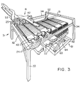
- Fig. 3 shows a perspective view of the apparatus for forming the stack of Fig. 1.
- Fig. 4 shows a side view of the apparatus of Fig. 3.
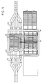
- Fig. 5 shows a top plan view of the apparatus of Fig. 3.
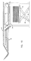
- Figs. 6-9 show sequential side views of the storage cycle of the apparatus of Fig. 3.
- Fig. 10 shows an end view of the storage cycle of the apparatus of Fig. 3.
- Fig. 1 shows the preferred embodiment of the formed stack of imbricated copy segments of the present invention.
- the vertical stack 1 includes a pallet 2 onto which a plurality of horizontal layers 4 are stacked.
- Each layer includes a separator sheet that supports three rows or segments 8 of imbricated copy stream.
- the segments of copy stream are made up of uniform copies of printed material 10 that are arranged in an overlapped manner.
- the printed material could include newspapers, magazines, signatures, etc., and can be bound, unbound, or folded (as shown).
- the copy stream segments remain in their imbricated or overlapped form which is a common form used in moving and conveying printed materials.
- the copy stream segments remain in a substantially flat configuration. This prevents deformation of individual copies since they aren't stored on their edges or on an arcuate path, as are the aforementioned prior art storage systems.
- the layers are stacked one on top of the other to form the most compact and space saving stack, possible.
- the stack is formed in a substantially cubic shaped unit that can be placed on a pallet, as shown. Also, the cubic form of the stack uses storage space more efficiently than any cylindrical storage system.
- Fig. 2 shows the sequence of the stack formation. Individual separator sheets 6 are placed atop a stack during formation. Three rows or segments 8 of copy stream are received in a holding area, and are subsequently shuttled over the separator sheet. The building of the new layer of the stack is complete when the three rows are dropped upon the separator sheet allowing another layer to begin.
- the dimensions of the stack 1, layers 4, rows 8, and articles 10 are important within the interrelationships of these components.
- Individual copies 10 have a storage width X and are overlapped by a distance Y upon the next copy.
- Fig. 2 show the copies as folded, but it should be appreciated that the copies could be single or multi-paged unfolded units. Additionally, the overlapped configuration could he made so that the folds of the copies are arranged along the length of the row instead of the width of the row, as shown.
- the overlapped or imbricated formation of the individual copies 10 is constructed by conventional printing equipment.
- the stack is formed from a plurality of in-feed conveyors of continuous streams of imbricated copies of width X and overlap Y, as will be explained later in the specification.
- the overlap Y is determined by the thickness and width of an individual copy, so that it may lay in a substantially flat manner in its overlapped configuration. The thicker the copy, or the less the width, the greater the overlap Y needs to be in order to preserve the substantially flat configuration of the copy stream.
- the stack is formed by separating the continuous streams into segments of length W. These segments are arranged in side-by-side parallel rows as shown to the right side of the stack within Fig. 2.
- the length W is predetermined as the width of the pallet 2.
- the overlap Y of the copy stream segments remains unchanged. This is directly different from the Harris stack of trays, noted above, where the overlap is removed by compacting the individual copies upon the individual trays.
- the number of rows or segments 8 upon each separator sheet is determined by the width of the copy W and the length of the pallet. In this case, three rows fit across the length of a single pallet.
- Fig. 3 shows the apparatus for forming the stack of Figs 1 and 2.
- the apparatus is divided into four separate units: the conveyor assembly 21, the apparatus support frame 31, the shuttle assembly 41, and the pallet elevator assembly 61.
- the conveyor assembly includes in-feed conveyors 22 and retrieval conveyors 23 for feeding and receiving a continuous imbricated copy stream of overlapped printed materials, respectively. Between the end 26 of conveyor 22 and the beginning 25 of conveyor 23 lies a central holding conveyor 24.
- the central conveyor is narrower in width than either of conveyors 22 or 23.
- the central conveyor is arranged to temporarily hold a segment of imbricated copy stream before being placed upon the stack or before being moved onto the retrieval conveyors 23.
- the apparatus support frame 31 includes a open rectangular frame 32 for holding the shuttle assembly 41.
- Four legs 33 at each corner hold the frame at a height greater than the height of a full pallet of imbricated copy stream allowing the pallet elevator assembly 61 to be positioned entirely within the frame 32.
- Parallel guide tracks 34 extend across the entire length of the frame and supports the shuttle assembly 41 for movement across the length of the frame 32.
- the shuttle assembly 41 includes a shuttle frame 42 which includes hinged gates 43 at the bottom of the shuttle frame.
- a hydraulic actuator 51 moves the shuttle assembly back and forth across the top of the frame 32 by extending or retracting the elongated piston rod 52.
- Guide bars 53 on either side of the shuttle assembly (only one of which is shown for clarity reasons in the broken away view of Fig. 3) cooperate with the guide tracks 34 of the frame to allow the shuttle assembly to move easily across the frame.
- the pallet elevator assembly 61 includes a base 62 positioned to the side of the conveyor assembly 21.
- a vertically movable platform 63 supports the pallet for movement up and down depending upon how full the stack is.
- Lifting arms 64 connect the platform to the base.
- Fig. 4 shows an end view of the apparatus of Fig. 3 to reveal several features hidden within Fig. 3.
- the guide bar 53 moves easily over the track because guide wheels 54 connected to the guide bar mate with the top of track 34 and allow the shuttle assembly to roll back and forth upon the frame.
- the platform 63 is moved up and down by a hydraulic actuator 65. Lifting arms 64 pivot to allow the flatform to remain in a horizontal plane.
- Fig. 4 also shows further details of the conveyor assembly.
- the most common form that printed materials are conveyed in is within a continuous overlapped copy stream.
- the conveyance can be done entirely upon endless belt conveyors such as the storage and retrieval conveyors 22 and 23 of Fig. 3.
- the printed materials can be delivered by a gripper conveyor 27 which deposits individually spaced printed copies upon an in-feed conveyor 22 to form an imbricated formation upon the endless belt conveyor.
- the gripper conveyor can also be used to pick up individual copies from the retrieval conveyor 23, as shown.
- Fig. 4 also shows the ends of the central conveyor 24 positioned between the ends of the storage and retrieval conveyors 22 and 23 to allow the easy transfer of the copy stream from one conveyor to the next.
- the central conveyor receives a segment or row of copy stream 8 from the continuous stream of copy 12 of the storage conveyor 22.
- the central conveyor temporarily holds the segments before the shuttle assembly transfers the segments to the stack.
- the shuttle assembly moves the segments of the copy stream back to the central conveyors 24 where they are subsequently transferred to the retrieval conveyors to form another continuous copy stream.
- Fig. 5 which shows a view from above the apparatus.
- Three separate storage conveyors 22 feed three central conveyors 24.
- the three central conveyors also feed three retrieval conveyors 23. It should be noted that the preferred embodiment allows the stack to be built with three rows, but it should also be appreciated that the invention could also be achieved with any number of rows from one to many.
- Fig. 6 is a cross-sectional view of the stack and apparatus at the beginning of a storage cycle.
- the gates 43 are hinged to the apparatus and are movable from a horizontal position, shown in Fig. 3, to a vertical retracted position, shown in Fig. 6.
- the gates are moved by hydraulic actuators 44 that include pistons that are pivotably connected to the gates to swing the gates between their vertically retracted and horizontally extended positions.
- the storage cycle of the apparatus is best seen within the sequential views of Figs. 6-9 and the end view of Fig. 10.
- the storage cycle is also the method by which the stack of the present invention is formed.
- the first step is to form three continuous rows of imbricated copy stream and convey these continous streams to the apparatus, as best seen in Fig. 10.
- the shuttle assembly 41 is positioned adjacent the in-feed conveyors 22 to the right of the stack 1 by the hydraulic actuator 51, as viewed within Fig. 6.
- the second step of the storage cycle is to divide the three continuous streams into three separate segments or rows 8 of a predetermined length and move these segments onto the central conveyors 24.
- the predetermined length is approximately equivalent to the length of the pallet or separator sheet. In this position, as seen in Fig.
- the hinged gates 43 are fully extended downwardly so that they do not interfere with the transfer of the segments to the central conveyors.
- the third step involves a locator for placing another separator sheet upon the stack, as best seen in Fig. 7. At this point the gates 43 are pivoted to a horizontal position to lift the copy stream segments 8 off of the surface of the conveyors 24.
- the fourth step involves pulling the shuttle back with the hydraulic actuator 51, as seen in Fig. 8, such that the segments 8 are positioned above the stack. As this time, the copy blocking partitions 45 are raised by hydraulic actuators 46 so that the shuttle may move to the left, as seen in Fig. 9. It should be noted that at all times, the original imbricated form of the printed materials is maintained.
- the stack of the present invention and the apparatus for assembling the stack are unique from the prior art machines.
- the relatively flat lay of the copy stream is the most stable way to store the individual copies, and allows the stack to remain stable even if the individual copies are unsymmetrical in size and/or shape.
- the prior art stacks and machines are not efficient in storing such unsymmetrical articles.
- the shuttle assembly of the apparatus forms an inherent buffer to the system to allow the removal of one stack while the shuttle is being loaded from the in-feed conveyors.
- the cubic shape of the stacks allow the stacks to be vertically stacked upon one another allowing greater efficiency of storage space within a publication facility or warehouse.
Landscapes
- Mechanical Engineering (AREA)
- Engineering & Computer Science (AREA)
- Pile Receivers (AREA)
- Packaging Of Special Articles (AREA)
- Sheets, Magazines, And Separation Thereof (AREA)
- Discharge By Other Means (AREA)
- Making Paper Articles (AREA)
- Separation, Sorting, Adjustment, Or Bending Of Sheets To Be Conveyed (AREA)
- Auxiliary Devices For And Details Of Packaging Control (AREA)
- Nitrogen Condensed Heterocyclic Rings (AREA)
- Electronic Switches (AREA)
- Ultra Sonic Daignosis Equipment (AREA)
- Pallets (AREA)
- Stacking Of Articles And Auxiliary Devices (AREA)
Abstract
Description
- The present invention relates to a storage assembly for storing imbricated or overlapped copies of printed and folded material upon a pallet. Within the field of printing it is common to temporarily store pre-printed material for later assembly with other printed materials. In the past, this was done by stacking individual printed copies, one on top of another, and placing these vertical stacks upon a pallet. In some cases, partial vertical stacks were tied together to form bundles which were subsequently placed upon pallets. In recent times, the printing industry has recognized that this form of storage is inefficient because it requires a machine to remove individual copies within an imbricated formation upon a conveyor belt and place them one on top of the other in a vertical stack. Conversely, when the stored materials are retrieved, they must be taken from a vertical stack and reformed into an imbricated form upon a conveyor. The machines for doing this type of storage and retrieval are complicated, subject to malfunction, and are relatively slow.
- One attempt at solving the problem of inefficient storage and retrieval of an imbricated copy stream has been widely adopted by the printing industry. This solution involves storing the individual printed copies within their imbricated formation directly upon large storage spools using a reel for winding the copies upon the spool. As the copy stream moves down the conveyor, the imbricated formation is placed upon a strip of continuous separating tape that is subsequently wound tightly upon large spools. A full spool of stored printed copies is cylindrical in shape and stores a single row of an imbricated copy stream. This technology was primarily developed and marketed by a European corporation, Ferag. The document EP-A-0 281 790 (Ferag) discloses a reeling machine for forming and dismantling such a spool.
- Although Ferag's reeling machines solve the problem of inefficient storage and retrieval by maintaining the imbricated formation during storage and retrieval, there are other disadvantages that arise in using Ferag's approach to the problem. First, the storage spools do not use storage space efficiently. The most efficient shape for storing materials is a cubic-shape, and the most common form to achieve the cubic-shape is upon a rectangular pallet. Cylindrical spools inherently waste storage space. Additionally, the cylindrical spools waste space at their respective centers. A second disadvantage of Ferag's machines is that cylindrical spools are inherently more difficult to handle. Pallets are the most common form of storage, and forklifts and other machines are built to handle rectangular pallets. Handling of cylindrical spools require special equipment that is more expensive and more complicated to maintain and operate. A third disadvantage is that the copy stream is stored on a curved path that temporarily deforms the normally flat printed copies. This makes handling the partially deformed copies more difficult, upon retrieval. A fourth disadvantage is that when handling and storing newspapers upon a spool, every other individual newspaper must be turned 180° prior to storing the newspapers. This is because the secondary folds of each newspaper make the newspaper thicker at one side, and the newspapers must be alternated to keep the spool balanced in width.
- Another alternative approach to vertical stacking of printed copies was developed by the Harris Corporation (now Harris Graphics, Inc.). That approach is disclosed in the document US-A-3,874,522 (Harris) which represents the closest state of the art. Harris used special trays to form substantially horizontal stacks of newspapers, signatures, and other types of printed material. As the imbricated copy stream exits the conveyor, the copy stream is compressed upon an elongated tray such that the individual copies are standing almost vertically on end. Individual trays can subsequently be stacked, one on top of the other upon a pallet.
- The Harris tray approach has not been found to be commercially viable within the printing industry. Although this approach allows the use of cubic-shaped storage units upon pallets, in contrast to Ferag's storage method, it still does not resolve the basic problem of inefficient destroying and reforming of the imbricated copy stream during storage and retrieval, respectively. Additionally, there are several other disadvantages associated with the use of Harris' storage method. First, this method requires specially formed trays that would be expensive. Second, some storage space is wasted between the top edge of the horizontal stack and the bottom of the next tray. Third, horizontal stacking of printed materials may deform the edges of individual printed copies. Fourth, the relatively narrow and long trays would be relatively unstable wen stacked upon one another in a pallet arrangement.
- Still another alternative approach is disclosed in the document DE-A-30.01.968. This document discloses a pallet with folded signatures thereon. According to this document, the signatures are supplied as a shingled stream of signatures and are directly deposited on the pallet while the latter is turning around an axis in one direction. As a result, the shingled signatures are continuously deposited around the axis, forming thereby a spiral-shaped stack. For dismantling the stack, the pallet is turned around the axis in the opposite direction.
- In addition to the problems associated with the use of the machines developed by Ferag and Harris, noted above, there are common problems associated with all prior art storage methods and machines. First, all of them are relatively slow in the total time that it takes to store and retrieve the printed copies from and to a conveyor. Even the amount of time that it takes to store and retrieve the copies with the Ferag method can be improved upon. Second, all of the prior art storage methods use a single row storage method. Efficiency in time and storage space may be improved with the use of a multiple row storage system. Finally, none of the prior art methods use a relatively flat and linear imprecated form for storing a printed copy stream. The relatively flat lay of the copy stream is the most stable way to store the individual copies, and allows the stack to remain stable even if the individual copies are unsymmetrical in size and/or shape. The prior art stacks and machines are not efficient in storing such unsymmetrical articles.
- It is an object of this invention to provide a method and apparatus for storing an imbricated copy stream upon a pallet that is faster and more efficient than present prior art systems.
- Another object of the invention is to provide a method and apparatus for forming a compact and cubic-shaped stack that takes up less space per printed copy than present prior art systems.
- Another object of the invention is to provide a method and apparatus for storing an imbricated copy stream in a relatively flat and horizontal position to avoid deformation of individual copies while in storage.
- It is a further object of the invention to provide a method and apparatus for forming a stack wherein the individual copy streams are self-supportive on the stack and do not require special supports for supporting individual printed copies.
- Other objects of the invention will be apparent hereinafter from the specification and from the recital of the appended claims, particularly when read in conjunction with the accompanying drawings.
- The present invention comprises a method and apparatus for forming a stack of imbricated copies of printed material on a pallet. A plurality of conveyors feed a shuttle assembly with imbricated copy streams upon a plurality of side-by-side rows. Once filled, the shuttle is positioned over a relatively flat separator sheet and drops the plurality of rows onto the separator sheet, thereby forming a single layer. The layer is placed directly upon a stack which is formed upon a pallet. The separator sheet of the formed layer is supported by the copy streams which lie below on the preceding separator sheet. The resulting stack is cubic-shaped and includes a plurality of layers of a plurality of side-by-side rows of relatively flat and horizontal imbricated copy streams that run the full width of the pallet. The same apparatus for forming the stack is also used to retrieve the copy streams from the stack and place the streams back upon the conveyors.
- Fig. 1 shows a perspective view of the formed pallet of imbricated copy streams of the present invention.
- Fig. 2 shows a perspective view of the sequential forming of individual layers within the stack of Fig. 1.
- Fig. 3 shows a perspective view of the apparatus for forming the stack of Fig. 1.
- Fig. 4 shows a side view of the apparatus of Fig. 3.
- Fig. 5 shows a top plan view of the apparatus of Fig. 3.
- Figs. 6-9 show sequential side views of the storage cycle of the apparatus of Fig. 3.
- Fig. 10 shows an end view of the storage cycle of the apparatus of Fig. 3.
- Fig. 1 shows the preferred embodiment of the formed stack of imbricated copy segments of the present invention. The vertical stack 1 includes a
pallet 2 onto which a plurality ofhorizontal layers 4 are stacked. Each layer includes a separator sheet that supports three rows orsegments 8 of imbricated copy stream. The segments of copy stream are made up of uniform copies of printedmaterial 10 that are arranged in an overlapped manner. The printed material could include newspapers, magazines, signatures, etc., and can be bound, unbound, or folded (as shown). - There are many important elements to the design of the stack shown in Fig. 1. First, the copy stream segments remain in their imbricated or overlapped form which is a common form used in moving and conveying printed materials. Second, the copy stream segments remain in a substantially flat configuration. This prevents deformation of individual copies since they aren't stored on their edges or on an arcuate path, as are the aforementioned prior art storage systems. Third, the layers are stacked one on top of the other to form the most compact and space saving stack, possible. Finally, the stack is formed in a substantially cubic shaped unit that can be placed on a pallet, as shown. Also, the cubic form of the stack uses storage space more efficiently than any cylindrical storage system.
- Fig. 2 shows the sequence of the stack formation.
Individual separator sheets 6 are placed atop a stack during formation. Three rows orsegments 8 of copy stream are received in a holding area, and are subsequently shuttled over the separator sheet. The building of the new layer of the stack is complete when the three rows are dropped upon the separator sheet allowing another layer to begin. - The dimensions of the stack 1, layers 4,
rows 8, andarticles 10 are important within the interrelationships of these components.Individual copies 10 have a storage width X and are overlapped by a distance Y upon the next copy. Fig. 2 show the copies as folded, but it should be appreciated that the copies could be single or multi-paged unfolded units. Additionally, the overlapped configuration could he made so that the folds of the copies are arranged along the length of the row instead of the width of the row, as shown. The overlapped or imbricated formation of theindividual copies 10 is constructed by conventional printing equipment. The stack is formed from a plurality of in-feed conveyors of continuous streams of imbricated copies of width X and overlap Y, as will be explained later in the specification. The overlap Y is determined by the thickness and width of an individual copy, so that it may lay in a substantially flat manner in its overlapped configuration. The thicker the copy, or the less the width, the greater the overlap Y needs to be in order to preserve the substantially flat configuration of the copy stream. - The stack is formed by separating the continuous streams into segments of length W. These segments are arranged in side-by-side parallel rows as shown to the right side of the stack within Fig. 2. The length W is predetermined as the width of the
pallet 2. The overlap Y of the copy stream segments remains unchanged. This is directly different from the Harris stack of trays, noted above, where the overlap is removed by compacting the individual copies upon the individual trays. The number of rows orsegments 8 upon each separator sheet is determined by the width of the copy W and the length of the pallet. In this case, three rows fit across the length of a single pallet. - Fig. 3 shows the apparatus for forming the stack of Figs 1 and 2. The apparatus is divided into four separate units: the conveyor assembly 21, the
apparatus support frame 31, theshuttle assembly 41, and thepallet elevator assembly 61. - The conveyor assembly includes in-
feed conveyors 22 andretrieval conveyors 23 for feeding and receiving a continuous imbricated copy stream of overlapped printed materials, respectively. Between theend 26 ofconveyor 22 and the beginning 25 ofconveyor 23 lies acentral holding conveyor 24. The central conveyor is narrower in width than either ofconveyors retrieval conveyors 23. - The
apparatus support frame 31 includes a openrectangular frame 32 for holding theshuttle assembly 41. Fourlegs 33 at each corner hold the frame at a height greater than the height of a full pallet of imbricated copy stream allowing thepallet elevator assembly 61 to be positioned entirely within theframe 32. Parallel guide tracks 34 extend across the entire length of the frame and supports theshuttle assembly 41 for movement across the length of theframe 32. - The
shuttle assembly 41 includes ashuttle frame 42 which includes hingedgates 43 at the bottom of the shuttle frame. Ahydraulic actuator 51 moves the shuttle assembly back and forth across the top of theframe 32 by extending or retracting theelongated piston rod 52. Guide bars 53 on either side of the shuttle assembly (only one of which is shown for clarity reasons in the broken away view of Fig. 3) cooperate with the guide tracks 34 of the frame to allow the shuttle assembly to move easily across the frame. - The
pallet elevator assembly 61 includes a base 62 positioned to the side of the conveyor assembly 21. A verticallymovable platform 63 supports the pallet for movement up and down depending upon how full the stack is. Liftingarms 64 connect the platform to the base. - Fig. 4 shows an end view of the apparatus of Fig. 3 to reveal several features hidden within Fig. 3. The
guide bar 53 moves easily over the track becauseguide wheels 54 connected to the guide bar mate with the top oftrack 34 and allow the shuttle assembly to roll back and forth upon the frame. Theplatform 63 is moved up and down by ahydraulic actuator 65. Liftingarms 64 pivot to allow the flatform to remain in a horizontal plane. - Fig. 4 also shows further details of the conveyor assembly. As related above, the most common form that printed materials are conveyed in is within a continuous overlapped copy stream. The conveyance can be done entirely upon endless belt conveyors such as the storage and
retrieval conveyors gripper conveyor 27 which deposits individually spaced printed copies upon an in-feed conveyor 22 to form an imbricated formation upon the endless belt conveyor. The gripper conveyor can also be used to pick up individual copies from theretrieval conveyor 23, as shown. - Fig. 4 also shows the ends of the
central conveyor 24 positioned between the ends of the storage andretrieval conveyors copy stream 8 from the continuous stream of copy 12 of thestorage conveyor 22. The central conveyor temporarily holds the segments before the shuttle assembly transfers the segments to the stack. When retrieving the copy stream from the stack, the shuttle assembly moves the segments of the copy stream back to thecentral conveyors 24 where they are subsequently transferred to the retrieval conveyors to form another continuous copy stream. Further details of the conveyor assembly can be seen in Fig. 5 which shows a view from above the apparatus. Threeseparate storage conveyors 22 feed threecentral conveyors 24. The three central conveyors also feed threeretrieval conveyors 23. It should be noted that the preferred embodiment allows the stack to be built with three rows, but it should also be appreciated that the invention could also be achieved with any number of rows from one to many. - Details of the hinged
gates 43 of the shuttle assembly may be seen in Fig. 6, which is a cross-sectional view of the stack and apparatus at the beginning of a storage cycle. Thegates 43 are hinged to the apparatus and are movable from a horizontal position, shown in Fig. 3, to a vertical retracted position, shown in Fig. 6. The gates are moved byhydraulic actuators 44 that include pistons that are pivotably connected to the gates to swing the gates between their vertically retracted and horizontally extended positions. - The storage cycle of the apparatus is best seen within the sequential views of Figs. 6-9 and the end view of Fig. 10. The storage cycle is also the method by which the stack of the present invention is formed. The first step is to form three continuous rows of imbricated copy stream and convey these continous streams to the apparatus, as best seen in Fig. 10. At this point, the
shuttle assembly 41 is positioned adjacent the in-feed conveyors 22 to the right of the stack 1 by thehydraulic actuator 51, as viewed within Fig. 6. The second step of the storage cycle is to divide the three continuous streams into three separate segments orrows 8 of a predetermined length and move these segments onto thecentral conveyors 24. The predetermined length is approximately equivalent to the length of the pallet or separator sheet. In this position, as seen in Fig. 6, the hingedgates 43 are fully extended downwardly so that they do not interfere with the transfer of the segments to the central conveyors. The third step involves a locator for placing another separator sheet upon the stack, as best seen in Fig. 7. At this point thegates 43 are pivoted to a horizontal position to lift thecopy stream segments 8 off of the surface of theconveyors 24. The fourth step involves pulling the shuttle back with thehydraulic actuator 51, as seen in Fig. 8, such that thesegments 8 are positioned above the stack. As this time, thecopy blocking partitions 45 are raised byhydraulic actuators 46 so that the shuttle may move to the left, as seen in Fig. 9. It should be noted that at all times, the original imbricated form of the printed materials is maintained. The final step, Fig. 9, involves placing thesegments 8 upon theseparator sheet 6 to form a new layer of the stack. This is done by vertically extending the hingedgates 43 to allow the segments of copy stream to drop upon the separator sheet. A cycle is completed by moving the shuttle back to its position to the right of the stack, Fig. 6, to receive the next three segments of copy stream, and moving the stack down the distance of one layer by the stack elevator assembly. - The stack of the present invention and the apparatus for assembling the stack are unique from the prior art machines. In addition to the points made above, there are other advantages to the present invention over the prior art machines. First, the relatively flat lay of the copy stream is the most stable way to store the individual copies, and allows the stack to remain stable even if the individual copies are unsymmetrical in size and/or shape. The prior art stacks and machines are not efficient in storing such unsymmetrical articles. Second, the shuttle assembly of the apparatus forms an inherent buffer to the system to allow the removal of one stack while the shuttle is being loaded from the in-feed conveyors. Finally, the cubic shape of the stacks allow the stacks to be vertically stacked upon one another allowing greater efficiency of storage space within a publication facility or warehouse.
- It should be apparent that many modifications could be made to the stack of imbricated copy streams, the method of forming the stack, and the apparatus for forming the stack which would still be encompassed within the scope of the appended claims.
Claims (14)
- Apparatus for forming a multi-layer stack (1) of imbricated copies (10) from a copy stream (12) fed to said apparatus, comprising means (24) for receiving at least one continuous row (8) of imbricated copies (10) of a predetermined length of said copy stream (12), a shuttle assembly (41) for transferring said at least one row (8) from said receiving means (24) onto a pallet (2), said shuttle assembly (41) having hinged gates (43) for lifting off the at least one row (8) of imbricated copies (10) of the surface of the receiving means (24) and for allowing the at least one row (8) of imbricated copies (10) to drop upon the pallet (2) thereby forming a layer of said multi-layer stack (1) of imbricated copies (10), and a locator for locating a separator sheet (6) on a preceding layer of said multi-layer stack (1).
- Apparatus of claim 1, characterized in that it comprises an apparatus support frame (31) including an open frame (32) for holding the shuttle assembly (41) and for allowing a movement of the shuttle assembly (41) across the length of the frame (32).
- Apparatus of claim 1 or 2, characterized in that it comprises a hydraulic actuator (51) for moving the shuttle assembly (41) back and forth across the top of the frame (32) for holding the shuttle assembly (41).
- Apparatus of any of claims 1 to 3, characterized in that the means (24) for receiving at least one continuous row (8) of imbricated copies (10) comprises at least one central holding conveyor (24), one for each row of imbricated copies.
- Apparatus of claim 4, characterized in that the central holding conveyor (24) is narrower than the row (8) of imbricated copies (10).
- Apparatus of any of claims 1 to 5, characterized in that it comprises a pallet elevator assembly (61) including a movable platform (63) for supporting a pallet (2) for movement up and down depending how full the stack (1) of imbricated copies (10) is.
- Apparatus of any of claims 1 to 6, characterized in that the receiving means (24) comprises three central holding conveyors (24) located side by side in a substantially horizontal plane for receiving three side-by-side rows (8) of imbricated copies (10), and in that the shuttle assembly (41) comprises three pairs of hinged gates (43) for simultaneously lifting off the rows (8) of imbricated copies (10) received by the three central holding conveyors (24) and for allowing the lifted-off row (8) of imbricated copies (10) to simultaneously drop upon the pallet (2).
- Apparatus of any of claims 1 to 7, characterized in that it comprises at least one infeed conveyor (22) for feeding a continuous imbricated copy stream (12) of overlapped printed material.
- Apparatus of claim 8, characterized in that it comprises three in-feed conveyors (22) for feeding three central holding conveyors (24).
- A vertically extending multi-layer stack (1) of copies (10) of printed material in an imbricated configuration forming at least one substantially straight row (8) of predetermined length comprising a support (2) onto which said plurality of layers (4) is stacked, a bottom layer (4) of at least one row (8) of imbricated copies (10), and at least one intermediate layer (4) of at least one row (8) of said imbricated copies (10), each said intermediate layer (4) including a separator sheet (6), that supports at least one row (8) of copies (10) and which is supported by the imbricated copies (10) of the preceding layer (41).
- The stack of claim 10, characterized in that each of said bottom layer and said at least one intermediate layer comprises three rows (8) of said copies (10) spaced side-by-side and parallel to one another.
- The stack of claim 11 characterized in that each of said bottom layer and said intermediate layers comprises three side-by-side rows (8) of said copy stream, each of said three rows (8) being substantially coplanar with and parallel to all other rows (8) in said bottom layer and said intermediate layer.
- A method of forming a multi-layer stack from a continuous copy stream comprising a plurality of substantially flat imbricated copies (10), said method comprising feeding at least one continuous row of predetermined length of said imbricated copies (10) to means (24) for receiving said row of imbricated copies, transferring said at least one row of imbricated copies (10) to a support (2) for supporting a stack of imbricated copies, thereby forming a bottom layer (4) of at least one row (8) of imbricated copies (10), positioning a separator sheet (6) by means of a locator on said bottom layer (4) of said multi-layer stack, continuing to feed said imbricated copies (10) to said means (24) for receiving to form at least one succeeding row (8) of predetermined length of said imbricated copies (10) and transferring said at least one succeeding row (8) on the precedingly positioned separator sheet.
- The method of claim 13, characterized in that it comprises forming three continuous rows (8) of imbricated copies (10) of predetermined length on three side-by-side located central holding conveyors (24), transferring said three rows (8) of imbricated copies (10) by means of a shuttle assembly (41) to a pallet (2) to form a substantially horizontal bottom layer (4) of the multi-layer stack (1) of copies (10) thereon, placing a separator sheet (6) by means of a locater upon the bottom layer (4) of copies (10), repeatedly forming three rows (8) of imbricated copies (10) of predetermined length and transferring them to the pallet (2) and dropping them on a separator sheet (6) previously placed on the preceding layer (4) of copies (10), thereby forming substantially horizontal intermediate layers being arranged on substantially horizontal and parallel planes to form a substantially cubic stack (1) of copies (10) of printed material.
Applications Claiming Priority (2)
| Application Number | Priority Date | Filing Date | Title |
|---|---|---|---|
| US724763 | 1991-07-02 | ||
| US07/724,763 US5311995A (en) | 1991-07-02 | 1991-07-02 | Stack for storing imbricated sheets |
Publications (3)
| Publication Number | Publication Date |
|---|---|
| EP0522890A2 EP0522890A2 (en) | 1993-01-13 |
| EP0522890A3 EP0522890A3 (en) | 1993-03-31 |
| EP0522890B1 true EP0522890B1 (en) | 1997-04-09 |
Family
ID=24911808
Family Applications (1)
| Application Number | Title | Priority Date | Filing Date |
|---|---|---|---|
| EP92401267A Expired - Lifetime EP0522890B1 (en) | 1991-07-02 | 1992-05-06 | Method and apparatus for storing imbricated sheets upon a pallet |
Country Status (8)
| Country | Link |
|---|---|
| US (2) | US5311995A (en) |
| EP (1) | EP0522890B1 (en) |
| JP (1) | JP2578049B2 (en) |
| AT (1) | ATE151384T1 (en) |
| DE (1) | DE69218845T2 (en) |
| DK (1) | DK0522890T3 (en) |
| FI (1) | FI100875B (en) |
| NO (1) | NO300170B1 (en) |
Families Citing this family (6)
| Publication number | Priority date | Publication date | Assignee | Title |
|---|---|---|---|---|
| US5336041A (en) * | 1992-03-12 | 1994-08-09 | Graphic Management Associates, Inc. | Storage and retrieval device and method for imbricated planar articles |
| DE19500560A1 (en) * | 1995-01-11 | 1996-07-18 | Kolbus Gmbh & Co Kg | Transporting continuously supplied printed products |
| US5826716A (en) * | 1995-11-13 | 1998-10-27 | Hayes Lemmerz International, Inc. | Wheel separator and method |
| US7799568B2 (en) * | 2003-10-07 | 2010-09-21 | The Johns Hopkins University | Authentication of products using molecularly imprinted polymers |
| US8955696B2 (en) | 2012-06-08 | 2015-02-17 | Tina Ting-Yuan Wang | Storage systems for milk bags |
| KR101968169B1 (en) * | 2018-11-28 | 2019-04-11 | 유정재 | Apparatus for transferring and stacking metal bar |
Family Cites Families (13)
| Publication number | Priority date | Publication date | Assignee | Title |
|---|---|---|---|---|
| US1386717A (en) * | 1920-10-04 | 1921-08-09 | Luckett James Stephen | Desk-tray |
| LU55769A1 (en) * | 1968-03-27 | 1969-10-22 | ||
| US3729367A (en) * | 1971-06-01 | 1973-04-24 | Oliver Tire & Rubber Co | Rubber product for tire recapping apparatus and method for making |
| US3874522A (en) * | 1973-05-16 | 1975-04-01 | Harris Intertype Corp | Signature handling system |
| US4230311A (en) * | 1979-01-23 | 1980-10-28 | Faltin Hans G | Storage pallet arrangements for folded paper items |
| US4416376A (en) * | 1982-09-30 | 1983-11-22 | Signode Corporation | Bag package and related method |
| JPH0430193Y2 (en) * | 1985-06-13 | 1992-07-21 | ||
| DE3643026A1 (en) * | 1986-12-17 | 1988-06-30 | Roland Man Druckmasch | TRANSPORT DEVICE, ESPECIALLY FOR FOLDED PRODUCTS |
| CH679993A5 (en) * | 1987-03-06 | 1992-05-29 | Ferag Ag | |
| GB8709851D0 (en) * | 1987-04-25 | 1987-05-28 | Langston Machine | Stacking boxes of corrugated board |
| US4927318A (en) * | 1988-02-09 | 1990-05-22 | Galpin Research, Limited Partnership | Method for forming, grasping and handling cubes of stacked printed products |
| SE468354B (en) * | 1988-09-15 | 1992-12-21 | Wamag Idab Ab | PROCEDURE AND DEVICE FOR INTERMEDIATE STORAGE OF JOURNALS |
| DE3940190A1 (en) * | 1989-12-05 | 1991-06-06 | Kolbus Gmbh & Co Kg | METHOD FOR LOADING AND UNLOADING PALLETS WITH STACKS OF FLAT PRODUCTS AND DEVICE FOR CARRYING OUT THE METHOD |
-
1991
- 1991-07-02 US US07/724,763 patent/US5311995A/en not_active Expired - Fee Related
-
1992
- 1992-04-02 NO NO921276A patent/NO300170B1/en not_active IP Right Cessation
- 1992-05-06 AT AT92401267T patent/ATE151384T1/en not_active IP Right Cessation
- 1992-05-06 DE DE69218845T patent/DE69218845T2/en not_active Expired - Fee Related
- 1992-05-06 DK DK92401267.7T patent/DK0522890T3/en active
- 1992-05-06 EP EP92401267A patent/EP0522890B1/en not_active Expired - Lifetime
- 1992-06-10 FI FI922685A patent/FI100875B/en not_active IP Right Cessation
- 1992-07-01 JP JP4197748A patent/JP2578049B2/en not_active Expired - Lifetime
-
1994
- 1994-03-01 US US08/204,556 patent/US5492444A/en not_active Expired - Fee Related
Also Published As
| Publication number | Publication date |
|---|---|
| NO921276L (en) | 1993-01-04 |
| FI100875B (en) | 1998-03-13 |
| EP0522890A3 (en) | 1993-03-31 |
| FI922685A7 (en) | 1993-01-03 |
| DK0522890T3 (en) | 1997-10-27 |
| NO921276D0 (en) | 1992-04-02 |
| NO300170B1 (en) | 1997-04-21 |
| FI922685A0 (en) | 1992-06-10 |
| DE69218845D1 (en) | 1997-05-15 |
| EP0522890A2 (en) | 1993-01-13 |
| JP2578049B2 (en) | 1997-02-05 |
| JPH06340363A (en) | 1994-12-13 |
| US5311995A (en) | 1994-05-17 |
| US5492444A (en) | 1996-02-20 |
| ATE151384T1 (en) | 1997-04-15 |
| DE69218845T2 (en) | 1997-11-20 |
Similar Documents
| Publication | Publication Date | Title |
|---|---|---|
| CN101489900B (en) | Device and method for the processing of stacks of sheets of securities into bundles and packs of bundles | |
| US5540545A (en) | Palletizing system | |
| US5716189A (en) | Palletizer and palletizing methods | |
| US5256028A (en) | Process for handling material | |
| US4977827A (en) | Signature handling apparatus | |
| US5311995A (en) | Stack for storing imbricated sheets | |
| US5730579A (en) | Bundle feed apparatus for delivering multiple bundles to a load former | |
| JPH0471810B2 (en) | ||
| FI81547B (en) | SAETT OCH ANLAEGGNING FOER HOPSAETTNING AV EN OLIKA PRODUKTFOERPACKNINGAR ELLER LIKNANDE OMFATTANDE TRANSPORTPALL. | |
| US5336041A (en) | Storage and retrieval device and method for imbricated planar articles | |
| JPH0332826A (en) | Methods for storing blank of pack and send- ing packing machine to folding unit | |
| US6189827B1 (en) | Process and apparatus for storing blanks | |
| US5437530A (en) | High-shelf storage apparatus | |
| EP1129843A1 (en) | Method and machine for separating blanks for cardboard boxes | |
| EP0365870B1 (en) | Signature handling apparatus | |
| JPS62180845A (en) | Methd and device for treating print, such as newspaper, magazine, etc. being fed under displaced and stacked state | |
| US20080317576A1 (en) | Method and device for feeding a number of flat subproducts to a serial subsequent processing | |
| CN223982776U (en) | A film roll grouping and packaging system | |
| JPH09142714A (en) | Device for automatically filling and stacking signatures | |
| JPH0610054B2 (en) | Palletizer | |
| JPH09142613A (en) | Magazine physical distribution system for bookbinding | |
| JP2000085717A (en) | Agricultural product boxing device | |
| GB2107690A (en) | Palletising equipment and process | |
| JPH03205230A (en) | Apparatus and method for taking out sheet material from cassette | |
| JPS629503B2 (en) |
Legal Events
| Date | Code | Title | Description |
|---|---|---|---|
| PUAI | Public reference made under article 153(3) epc to a published international application that has entered the european phase |
Free format text: ORIGINAL CODE: 0009012 |
|
| AK | Designated contracting states |
Kind code of ref document: A2 Designated state(s): AT BE CH DE DK ES FR GB GR IT LI LU MC NL PT SE |
|
| PUAL | Search report despatched |
Free format text: ORIGINAL CODE: 0009013 |
|
| AK | Designated contracting states |
Kind code of ref document: A3 Designated state(s): AT BE CH DE DK ES FR GB GR IT LI LU MC NL PT SE |
|
| RAP1 | Party data changed (applicant data changed or rights of an application transferred) |
Owner name: GRAPHIC MANAGEMENT ASSOCIATES, INC. |
|
| 17P | Request for examination filed |
Effective date: 19930802 |
|
| 17Q | First examination report despatched |
Effective date: 19950511 |
|
| GRAG | Despatch of communication of intention to grant |
Free format text: ORIGINAL CODE: EPIDOS AGRA |
|
| GRAH | Despatch of communication of intention to grant a patent |
Free format text: ORIGINAL CODE: EPIDOS IGRA |
|
| GRAH | Despatch of communication of intention to grant a patent |
Free format text: ORIGINAL CODE: EPIDOS IGRA |
|
| GRAA | (expected) grant |
Free format text: ORIGINAL CODE: 0009210 |
|
| AK | Designated contracting states |
Kind code of ref document: B1 Designated state(s): AT BE CH DE DK ES FR GB GR IT LI LU MC NL PT SE |
|
| PG25 | Lapsed in a contracting state [announced via postgrant information from national office to epo] |
Ref country code: NL Effective date: 19970409 Ref country code: IT Free format text: LAPSE BECAUSE OF FAILURE TO SUBMIT A TRANSLATION OF THE DESCRIPTION OR TO PAY THE FEE WITHIN THE PRE;WARNING: LAPSES OF ITALIAN PATENTS WITH EFFECTIVE DATE BEFORE 2007 MAY HAVE OCCURRED AT ANY TIME BEFORE 2007. THE CORRECT EFFECTIVE DATE MAY BE DIFFERENT FROM THE ONE RECORDED.SCRIBED TIME-LIMIT Effective date: 19970409 Ref country code: GR Free format text: LAPSE BECAUSE OF FAILURE TO SUBMIT A TRANSLATION OF THE DESCRIPTION OR TO PAY THE FEE WITHIN THE PRESCRIBED TIME-LIMIT Effective date: 19970409 Ref country code: ES Free format text: THE PATENT HAS BEEN ANNULLED BY A DECISION OF A NATIONAL AUTHORITY Effective date: 19970409 Ref country code: BE Effective date: 19970409 |
|
| REF | Corresponds to: |
Ref document number: 151384 Country of ref document: AT Date of ref document: 19970415 Kind code of ref document: T |
|
| REG | Reference to a national code |
Ref country code: CH Ref legal event code: NV Representative=s name: KIRKER & CIE SA Ref country code: CH Ref legal event code: EP |
|
| PG25 | Lapsed in a contracting state [announced via postgrant information from national office to epo] |
Ref country code: LU Free format text: LAPSE BECAUSE OF NON-PAYMENT OF DUE FEES Effective date: 19970506 |
|
| REF | Corresponds to: |
Ref document number: 69218845 Country of ref document: DE Date of ref document: 19970515 |
|
| ET | Fr: translation filed | ||
| PG25 | Lapsed in a contracting state [announced via postgrant information from national office to epo] |
Ref country code: PT Effective date: 19970709 |
|
| NLV1 | Nl: lapsed or annulled due to failure to fulfill the requirements of art. 29p and 29m of the patents act | ||
| REG | Reference to a national code |
Ref country code: DK Ref legal event code: T3 |
|
| PG25 | Lapsed in a contracting state [announced via postgrant information from national office to epo] |
Ref country code: MC Effective date: 19971130 |
|
| PLBE | No opposition filed within time limit |
Free format text: ORIGINAL CODE: 0009261 |
|
| STAA | Information on the status of an ep patent application or granted ep patent |
Free format text: STATUS: NO OPPOSITION FILED WITHIN TIME LIMIT |
|
| 26N | No opposition filed | ||
| REG | Reference to a national code |
Ref country code: GB Ref legal event code: IF02 |
|
| PGFP | Annual fee paid to national office [announced via postgrant information from national office to epo] |
Ref country code: GB Payment date: 20040505 Year of fee payment: 13 |
|
| PGFP | Annual fee paid to national office [announced via postgrant information from national office to epo] |
Ref country code: SE Payment date: 20040506 Year of fee payment: 13 |
|
| PGFP | Annual fee paid to national office [announced via postgrant information from national office to epo] |
Ref country code: FR Payment date: 20040510 Year of fee payment: 13 |
|
| PGFP | Annual fee paid to national office [announced via postgrant information from national office to epo] |
Ref country code: AT Payment date: 20040512 Year of fee payment: 13 |
|
| PGFP | Annual fee paid to national office [announced via postgrant information from national office to epo] |
Ref country code: DE Payment date: 20040513 Year of fee payment: 13 |
|
| PGFP | Annual fee paid to national office [announced via postgrant information from national office to epo] |
Ref country code: CH Payment date: 20040517 Year of fee payment: 13 Ref country code: DK Payment date: 20040517 Year of fee payment: 13 |
|
| PG25 | Lapsed in a contracting state [announced via postgrant information from national office to epo] |
Ref country code: GB Free format text: LAPSE BECAUSE OF NON-PAYMENT OF DUE FEES Effective date: 20050506 Ref country code: AT Free format text: LAPSE BECAUSE OF NON-PAYMENT OF DUE FEES Effective date: 20050506 |
|
| PG25 | Lapsed in a contracting state [announced via postgrant information from national office to epo] |
Ref country code: SE Free format text: LAPSE BECAUSE OF NON-PAYMENT OF DUE FEES Effective date: 20050507 |
|
| PG25 | Lapsed in a contracting state [announced via postgrant information from national office to epo] |
Ref country code: LI Free format text: LAPSE BECAUSE OF NON-PAYMENT OF DUE FEES Effective date: 20050531 Ref country code: DK Free format text: LAPSE BECAUSE OF NON-PAYMENT OF DUE FEES Effective date: 20050531 Ref country code: CH Free format text: LAPSE BECAUSE OF NON-PAYMENT OF DUE FEES Effective date: 20050531 |
|
| PG25 | Lapsed in a contracting state [announced via postgrant information from national office to epo] |
Ref country code: DE Free format text: LAPSE BECAUSE OF NON-PAYMENT OF DUE FEES Effective date: 20051201 |
|
| REG | Reference to a national code |
Ref country code: CH Ref legal event code: PL |
|
| EUG | Se: european patent has lapsed | ||
| GBPC | Gb: european patent ceased through non-payment of renewal fee |
Effective date: 20050506 |
|
| PG25 | Lapsed in a contracting state [announced via postgrant information from national office to epo] |
Ref country code: FR Free format text: LAPSE BECAUSE OF NON-PAYMENT OF DUE FEES Effective date: 20060131 |
|
| REG | Reference to a national code |
Ref country code: DK Ref legal event code: EBP |
|
| REG | Reference to a national code |
Ref country code: FR Ref legal event code: ST Effective date: 20060131 |