EP0522846A1 - Method and apparatus for controlling weft inserting in jet loom - Google Patents
Method and apparatus for controlling weft inserting in jet loom Download PDFInfo
- Publication number
- EP0522846A1 EP0522846A1 EP92306280A EP92306280A EP0522846A1 EP 0522846 A1 EP0522846 A1 EP 0522846A1 EP 92306280 A EP92306280 A EP 92306280A EP 92306280 A EP92306280 A EP 92306280A EP 0522846 A1 EP0522846 A1 EP 0522846A1
- Authority
- EP
- European Patent Office
- Prior art keywords
- information
- weft inserting
- weft
- basis
- control
- Prior art date
- Legal status (The legal status is an assumption and is not a legal conclusion. Google has not performed a legal analysis and makes no representation as to the accuracy of the status listed.)
- Granted
Links
Images


Classifications
-
- D—TEXTILES; PAPER
- D03—WEAVING
- D03D—WOVEN FABRICS; METHODS OF WEAVING; LOOMS
- D03D51/00—Driving, starting, or stopping arrangements; Automatic stop motions
- D03D51/18—Automatic stop motions
- D03D51/34—Weft stop motions
-
- D—TEXTILES; PAPER
- D03—WEAVING
- D03D—WOVEN FABRICS; METHODS OF WEAVING; LOOMS
- D03D47/00—Looms in which bulk supply of weft does not pass through shed, e.g. shuttleless looms, gripper shuttle looms, dummy shuttle looms
- D03D47/28—Looms in which bulk supply of weft does not pass through shed, e.g. shuttleless looms, gripper shuttle looms, dummy shuttle looms wherein the weft itself is projected into the shed
- D03D47/30—Looms in which bulk supply of weft does not pass through shed, e.g. shuttleless looms, gripper shuttle looms, dummy shuttle looms wherein the weft itself is projected into the shed by gas jet
- D03D47/3026—Air supply systems
- D03D47/3053—Arrangements or lay out of air supply systems
-
- D—TEXTILES; PAPER
- D03—WEAVING
- D03D—WOVEN FABRICS; METHODS OF WEAVING; LOOMS
- D03D47/00—Looms in which bulk supply of weft does not pass through shed, e.g. shuttleless looms, gripper shuttle looms, dummy shuttle looms
- D03D47/28—Looms in which bulk supply of weft does not pass through shed, e.g. shuttleless looms, gripper shuttle looms, dummy shuttle looms wherein the weft itself is projected into the shed
- D03D47/30—Looms in which bulk supply of weft does not pass through shed, e.g. shuttleless looms, gripper shuttle looms, dummy shuttle looms wherein the weft itself is projected into the shed by gas jet
- D03D47/3026—Air supply systems
- D03D47/3033—Controlling the air supply
-
- D—TEXTILES; PAPER
- D03—WEAVING
- D03D—WOVEN FABRICS; METHODS OF WEAVING; LOOMS
- D03D51/00—Driving, starting, or stopping arrangements; Automatic stop motions
- D03D51/007—Loom optimisation
Definitions
- This invention relates to a method and an apparatus for controlling weft inserting in an air jet loom, a water jet loom or the like, and more particularly, to a method and an apparatus for controlling weft inserting in a jet loom provided with an actuator for weft inserting.
- control parameter such as a pressure of the fluid jetted from a main nozzle (designated as “main pressure” in the present invention) or a pressure jetted from a subnozzle (designated as “subpressure” in the present invention) and then controlling actuators thereof on the basis of either one of running information such as the rotational angle (arrival angle) of a main shaft when a weft inserted into a warp shed reaches a predetermined position, stopping machine information such as the causes for stopping a weaving machine and the stop frequency thereof and quality information such as slack filling in woven fabrics and the frequency thereof.
- running information such as the rotational angle (arrival angle) of a main shaft when a weft inserted into a warp shed reaches a predetermined position
- stopping machine information such as the causes for stopping a weaving machine and the stop frequency thereof
- quality information such as slack filling in woven fabrics and the frequency thereof.
- the correction of the control conditions due to the running information is practised in short period (one period as the shortest cycle) during the operation of the weaving machine.
- the correction of the control conditions due to the stopping machine information or quality information is practicable only when the weaving machine happens to stop or when the product quality is lowered, these corrections are practised in longer period.
- the directions to be corrected may sometimes be different depending on the running information, the stopping machine information and the quality information.
- the techniques known per se only correct the control conditions using single information selected out of the running information, the stopping machine information and the quality information, as disclosed in Japanese Patent Public Disclosure (KOKAI) Nos. 56-107046 and 63-75149. Therefore, the control conditions could not be corrected due to a plurality of information, and an operator could not help relying on the manual corrections by the operator's professional feelings and experiences without relying on any automatic corrections for the purpose of these corrections.
- a method for controlling weft inserting in the present invention comprises the steps of obtaining the control condition of an actuator for weft inserting on the basis of at least two kinds of information including running information representing the running state of weft, and stopping machine information representing the stopping state of a weaving machine or quality information representing the quality of a fabric quality, by use of at least one means selected out of the following means: a) an expert system constituted according to a control algorithm for weft inserting, b) a data table having data for weft inserting constituted according to the control algorithm for weft inserting, and c) an approximate expression by use of the information; and controlling the preceding actuator on the basis of the control condition thus obtained.
- An apparatus for controlling weft inserting in the invention comprises: information generation means for generating at least two kinds of information including running information representing the running state of weft, and stopping machine information representing the stopping state of a weaving machine or quality information representing the quality state of woven fabric; control condition-generating means selected out of a) an expert system constituted according to a control algorithm for weft inserting and for obtaining a control condition of an actuator for weft inserting on the basis of the informations, b) operating means provided with a data table having data for weft inserting and constituted according to a control algorithm for weft inserting and for obtaining a control condition of the actuator for weft inserting on the basis of the information and the preceding data; and c) operating means provided with memory means for storing a plurality of approximate expressions for calculating a control condition of the actuator for weft inserting using the informations, and for obtaining the preceding control condition using the preceding information and the preceding approximate expression; and means for controlling the preceding actuator on the basis of the obtained
- the control algorithm is composed of at least two kinds of information including running information with either stopping machine information or quality information in the following manner: "Increase the main pressure, irrespective of leading end troubles, blow-by at the leading ends, barrel slippings, an average value and a dispersion of final release timing, and an average value and a dispersion of arrival timing, when the slack fillings often happen”; “Do not change the main pressure when no slack filling happens, but when leading end troubles, blow-by at the leading ends and barrel slippings often happen and when the slack fillings happened before.” "Decrease the main pressure, irrespective of leading end troubles, blow-by at the leading ends, barrel slipping, an average value and a dispersion of final release timing, and an average value and a dispersion of arrival timing, when no slack filing happens, but when leading end troubles, blow-by at the leading ends and barrel slippings often happen and when no slack fillings
- the expert system obtains the control condition on the basis of a plurality of control rules using at least two kinds of information including running information with either stopping machine information or quality information, for example, in the following manner: "Increase the main pressure by P, when a present slack filling frequency is often".
- the p may be a value for actually altering the pressure, a value for altering an objective value of the pressure, a value in common to the control rules or a different value every each control rule.
- control condition obtained from the control condition-generating means is supplied to control means such as a pressure controller from the control condition-generating means, and the control means controls an actuator such as a pressure regulator on the basis of the supplied control condition.
- weft inserting can be controlled by using not only the running information under operation but also the stopping machine information or the quality information, and the weft inserting can be done under the satisfactory condition to these information.
- the operating means stores, for example, data such as a corrected content of the control object such as a main pressure or a corrected content of an objective value of the control object in the data table, every the combination of the running information with either the stopping machine information or the quality information, reads out the data of an address corresponding to the combination of the running information with either the stopping machine information or the quality information from the data table, and obtains a control condition on the basis of the read-out data.
- the data may be a value for actually altering the control condition such as a pressure, or a value for altering an objective value of the control condition.
- the data is a value corresponding to the combination of these information.
- Weft inserting can be controlled by use of not only any running information under operation but also any stopping machine information or any quality information even by the control method and the control apparatus which utilize the operating means provided with the preceding data table as the control condition-generating means, and the weft inserting can also be done under the satisfactory condition to these information.
- some weaving machines are actually operated according to a skillful operation to obtain the data such as the running information, the stopping machine information or the quality information, and the control condition for the actuator at that time. Then, the approximate expressions can be obtained from these data by a double regression analysis, for example. The approximate expressions thus obtained approximate to the control algorithm considered by the skillful operators.
- weft inserting can also be controlled by using not only the running information under operation but also the stopping machine information or the quality information, and the weft inserting can be done under the satisfactory condition to these information.
- a weaving machine 10 is a jet loom of either an air or water type, and includes a drum type length measuring storage unit 14 for a weft 12.
- the weft 12 is rolled around a weft package 16.
- the weft 12 is also supplied from the weft package 16 to a weft inserting unit 18 known per se through the length measuring storage unit 14 and is inserted in a warp shed 22 from the preceding weft inserting unit.
- the weft 12 is prevented 12 is prevented from the release from a length measuring-and-storage drum 28 by an engagement pin 26 having the top portion operated by an electromagnetic solenoid 24, and is stored while being rolled by a predetermined length around the circumferential surface of the drum 28 through the rotation of a yarn guide 30.
- the weft 12 is released from the drum 28 by the release of the pin 26, and is cut off after the weft 12 is ejected from a main nozzle 32 of the weft inserting unit 18 together with fluid so as to be inserted into the warp shed 22.
- the weft inserting unit 18 includes a plurality of subnozzles 34 for jetting the fluid to advance the weft 12 to a predetermined direction at the weft inserting time.
- Working fluid of a pressure source 36 is supplied to the main nozzle 32 through a pressure regulator 38 and a switching valve 40.
- the working fluid of the pressure source 36 is supplied to each subnozzle 34 through a pressure regulator 42 and a corresponded switching valve 44.
- the weaving machine 10 also includes a motor 48 for a main shaft 46 for driving a reed.
- the rotation of the motor 48 is transmitted from a connection mechanism 50 to the main shaft 46.
- the main shaft 46 is attached with both an encoder 52 for generating a rotational angle signal corresponding to the rotational angle of the main shaft and an electromagnetic brake 54 for the main shaft 46.
- the length measuring storage unit 14 and the weft inserting unit 18 are driven together with healds and reed in synchronism with the rotation of the main shaft 46.
- a weft inserting control apparatus for the weaving machine 10 includes a detection circuit 60 for detecting operating information with respect to the weft inserting of the weaving machine, a memory circuit 62 for storing various information, data or the like, a setting circuit 64 for manually setting various information, an operation circuit 66 for obtaining a control condition on the basis of the information and data from each of the preceding circuits 60 through 64, a pressure controller 68 for controlling the pressure regulators 38 and 42 on the basis of the signal supplied from the operation circuit 66, a timing controller 70 for driving the switching valves 40 and 44 and the electromagnetic solenoid 24 on the basis of the signal supplied from the operation circuit 66, and a tension controller 72 for controlling a warp tension mechanism (not shown) on the basis of the signal supplied from the operation circuit 66.
- the operating information includes running information, stopping machine information, quality information and a pick number. Therefore, the respective output signals 74a, 76a, 78a and 52a of a first detector 74 for detecting that the weft 12 is inserted up to a final position thereof, a second detector 76 for detecting that the weft 12 is inserted up to not less than a permissible position thereof, a release sensor 78 for detecting that the weft 12 is released from the length measuring storage unit 14 and an encoder 52 are supplied to the detection circuit 60. The output signal 78a of the release sensor 78 is also supplied to the timing controller 70.
- the detection circuit 60 is provided with a circuit 60a for detecting the weft running state, a circuit 60b for detecting the cause of the stopping of the weaving machine, a circuit 60c for detecting a fabric quality and a circuit 60d for detecting picks or the like.
- the running information for example, use is made of an average value and a dispersion of weft running timing such as so-called release timing like a rotational angle (release angle) of the main shaft when the weft at a predetermined winding stitch is released from the length measuring storage unit and so-called arrival timing like a rotational angle (arrival angle) of the main shaft when a leading end portion of the weft reaches a predetermined position.
- release timing like a rotational angle (release angle) of the main shaft when the weft at a predetermined winding stitch is released from the length measuring storage unit
- arrival timing like a rotational angle (arrival angle) of the main shaft when a leading end portion of the weft reaches a predetermined position.
- an average value of the running timing for example, at least one selected from the following can be used, that is:
- a dispersion of the running timing for example, at least one selected from the following can be used, that is:
- the stopping machine information is a stopping machine frequency every each cause of the stopping machine.
- a stopping machine cause there are a so-called “H1 stop” due to the fact that the weft 12 cannot be detected by the first detector 74 and a so-called “H2 stop” due to the fact that the weft 12 can be detected by the second detector 76.
- the stopping machine information and the quality information can, however, be obtained by the input of these signals, and in case where these sensors are not available, the preceding information can be obtained by the manual input on the basis of the operator's judgement. Furthermore, the quality information is inputted depending on the sensor or the operator's judgement during the operation of the weaving machine or after the machine stops.
- control parameters for example, at least one selected from the following can be used, that is:
- the kinds of threads, the representative values (average value, median, mode, fastest value, latest value or the like) of the objective values in the control parameters, the dispersion (standared deviation, range or the like) of the objective values in the control parameters, the sample number (pick number, woven length, time) and the upper or lower limit value of operation content are all set in the setter 64.
- any of corrected values of a plurality of control rules and the control conditions and the approximate expressions are stored in the memory circuit 62, depending on selecting either of the expert system, the data table and the approximate expressions for the control conditions.
- the corrected values of a plurality of control rules and the control conditions are prepared according to a predetermined control algorithm.
- the approximate expressions are obtained by causing the weaving machine to be actually operated by a skillful operator to give data of the running information, stopping machine information or quality information, the control conditions for the actuator or the like at that time and then making the double regression analysis from the preceding data.
- various automatic control systems on the basis of the running information are generally attached to the weaving machine as the control during the operation of the weaving machine.
- the automatic control system there are some systems for automatically varying the pressure and/or the jet timing so that an angle for weft to reach a weft sensor provided at a predetermined position in the weft inserting path may become constant. If an automatic control system on the basis of the stopping machine information or the quality information made after the weaving machine stops is merely added to this automatic control system, both of these automatic control systems interfere with each other and the functions thereof cannot be activated together.
- any control conditions are corrected on the basis of the combined control algorithm with the running information, the stopping machine information and the quality information, and consequently, a control can be performed under the satisfactory condition to each information.
- the objective value to be used in the existing automatic control system on the basis of the running information while using this automatic control system as it is is corrected by the automatic control system on the basis of the stopping machine information and the quality information, and consequently, a control is performed under the satisfactory condition to each information without any mutual interferences in the automatic control systems.
- control algorithm on the basis of the above description (1).
- control algorithm is available for the case where the control condition is a main pressure, but it may be other control conditions in the above description or the combinations thereof.
- A1 Increase the main pressure, independently of any leading end troubles, a blow-by at the leading ends, a barrel slipping, an average value and a dispersion of final release timing and an average value and a dispersion of arrival timing, when there are slack fillings.
- A2 Do not change the main pressure, when there is no slack filling, and any leading end troubles, blowby at the leading ends and barrel slippings often happen but when there were slack fillings before.
- A3 Decrease the main pressure, independently of an average value and a dispersion of final release timing and an average value and a dispersion of arrival timing, when there is no slack filling, any leading end troubles, blow-by at the leading ends and barrel slippings often happen and there was no slack filling before.
- A4 Do not change the main pressure, when there is no slack filling, and any leading end troubles, blowby at the leading ends and barrel slippings happen a little, but when there were slack fillings before or any leading end troubles, blow-by at the leading ends and barrel slippings did not happen before.
- A5 Increase the main pressure, when there is no slack filling, and any leading end troubles, blow-by at the leading ends and barrel slippings happen a little, but when there was no slack filling before, any leading end troubles, blow-by at the leading ends and barrel slippings happened a little before and an average value of final release timing is late or a dispersion thereof is large.
- A6 Increase the main pressure, when there is and was no slack filling and any leading end troubles, blowby at the leading ends and barrel slippings happen a little and happened a little before, but when an average value of final release timing is fast, a dispersion of final release timing is small, an average value of arrival timing is late and a dispersion of arrival timing is large.
- A7 Increase the main pressure, when there is and was no slack filling and any leading end troubles, blowby at the leading ends and barrel slippings happen a little and happened a little before, but when an average value of final release timing is fast, a dispersion of final release timing is small, an average value of arrival timing is delayed and a dispersion of arrival timing is small.
- A8 Do not change the main pressure, when there is and was no slack filling and any leading end troubles, blow-by at the leading ends and barrel slippings happen a little and happened a little before, but when an average value of final release timing is fast, a dispersion of final release timing is small, an average value of arrival timing is fast and a dispersion of arrival timing is large.
- A9 Decrease the main pressure, when there is and was no slack filling and any leading end troubles, blowby at the leading ends and barrel slippings happen a little and happened a little before, but when an average value of final release timing is fast, a dispersion of final release timing is small, an average value of arrival timing is fast and a dispersion of arrival timing is small.
- the control condition is corrected if a slack filling happens even only at one time.
- the control condition is corrected depending on the generation frequencies thereof. It can be judged by comparing the generation ratios between the generation times during a certain period of time (hour, pick number and woven length) and each stopping machine cause to the total stopping machine times during the certain period of time with the limiting values thereof whether the frequencies are "often" or "small".
- the word "before” can mean an arbitrary time in the past, and for example, it can be set as a measure of the time while a piece of weft package is consumed. Furthermore, the definitions such as “small”, “large”, “fast”, and “late” can be standardized using the corresponding objective values and limiting values.
- A10 Quicken the objective value in the average value of arrival timing. (Increase the main pressure), when there were slack fillings.
- A11 Delay the objective values in the average values of final release timing and arrival timing and enlarge the objective values of both dispersion (Decrease the main pressure.), when any leading end troubles often happen.
- A12 Delay the objective values in the average values of final release timing and arrival timing and enlarge the objective values of both dispersions (Decrease the main pressure.), when any blow-by at the leading ends often happens.
- A13 Delay the objective values in the average values of final release timing and arrival timing and enlarge the objective values of both dispersions (Decrease the main pressure.), when any barrel slippings often happen.
- control algorithm as described above can also be prepared with respect to the preceding other control conditions, and it may be prepared using other information as well.
- the weft inserting control apparatus uses the expect system, a plurality of control rules prepared according to the preceding control algorithm are stored in the memory circuit 62.
- a plurality of data for weft inserting prepared according to the preceding control algorithm are stored in the memory circuit.
- the approximate expression is stored in the memory circuit 62.
- ⁇ M f( ⁇ k - ⁇ k0, ⁇ k- ⁇ k0, ⁇ t - ⁇ t0, ⁇ t - ⁇ t0, y, s) wherein,
- the preceding approximate expression can be obtained by actually operating the weaving machine, experimentally recording each value of input variables at that time and the corrected content by a skillful operator, and making a double regression analysis using these values.
- the objective value ⁇ kO in the average value of final release timing, the objective value ⁇ k0 in the dispersion of final release timing, the objective value ⁇ t0 in the average value of arrival timing, and the objective value ⁇ t0 in the dispersion of arrival timing are preliminarily set in the setting circuit 64, respectively.
- the operation circuit 66 calculates the average value ⁇ k and the dispersion ⁇ k of final release timing and the average value ⁇ t and the dispersion ⁇ t of arrival timing on the basis of the final release timing and the arrival timing which are outputted from the running state detection circuit 60a.
- the operation circuit 66 also calculates a total value due to the leading end troubles, blow-by at the leading ends and barrel slippings, that is, a total stopping machine frequency, a sum of the total individual cause stopping machine frequency, that is, a whole stopping machine frequency, and a ratio s of the total stopping machine frequency to the whole stopping machine frequency on the basis of an individual cause stopping machine signal which is outputted from the stopping machine cause detection circuit 60b.
- the operation circuit 66 calculates a slack filling frequency y on the basis of a slack filling signal which is outputted from a fabric quality detection circuit 60c, and further calculates a pick number (weft inserting frequency) on the basis of a detection signal which is outputted from the pick detection circuit 60d.
- the operation circuit 66 calculates a corrected content ⁇ M of the main pressure and adds the calculated corrected content to the present main pressure to thereby give a new main pressure.
- the operation circuit 66 provides the calculated main pressure in a pressure controller 68 as it is in a form of a new main pressure in case where the new main pressure is within the upper and lower limit values set in the setting circuit 64, while the operation circuit 66 provides a limiting value in the pressure controller 68 as a new main pressure in case where the calculated main pressure is at the outside of the upper and lower limit values.
- the pressure controller 68 adjusts the main pressure into a new value.
- the weft inserting is made so that satisfy any of the running state, stopping state of the weaving machine and fabric quality thereof.
- the preceding process is carried out every each predetermined pick number (or every a certain period of time.)
- the preceding approximate expression may be calculated every each kind of thread.
- Each coefficient for each kind of thread is defined as follows: and these coefficients may be incorporated into the approximate expression.
- the storage capacity of the memory circuit becomes remarkably small.
- the operation circuit 66 comprises a circuit 80 for statistically processing the output signals received from the running state detection circuit 60a, the stopping machine cause detection circuit 60b and the fabric quality detection circuit 60c, a counter 82 for counting the output signal from the pick detection circuit 60d until the output signal becomes equal to the value set in the setting circuit 64, an inference engine 84 for inferring correction values for control conditions on the basis of a plurality of control rules stored in the memory circuit 62, and a controller 86 for calculating renewed control conditions on the basis of the output signals from the circuits 64, 80, 82, and 84.
- control rules R1 through R9 in case of setting the control condition as the main pressure will be shown in the following.
- the control rules R1 through R9 correspond to the control algorithms A1 through A9, respectively.
- the average value and the dispersion ⁇ k and ⁇ k of final release timing and the average value and the dispersion ⁇ t and ⁇ t of arrival timing in the preceding control rules R1 through R9 are calculated in the statistical processing circuit 80 on the basis of the final release timing and arrival timing which are generated from the running state detection circuit 60a, respectively.
- the total stopping machine frequency due to the leading troubles, blow-by at the leading ends and barrel slippings, the whole stopping machine frequency, the ratio s of the total stopping machine frequency to the present whole stopping machine frequency and the ratio s′ of the total stopping machine frequency to the previous whole stopping machine frequency, respectively, are calculated in the statistical processing circuit 80 on the basis of the individual cause stopping machine signals generated from the stopping machine cause detection circuit 60b. Furthermore, the present slack filling frequency y and the previous slack filling frequency y′ are calculated in the statistical processing circuit 80 on the basis of the slack filling signals generated from the fabric quality detection circuit 60c.
- the threshold ⁇ k0 in the average value of final release timing, the threshold ⁇ k0 in the dispersion of final release timing, the threshold ⁇ t0 in the average value of arrival timing, the threshold ⁇ t0 in the dispersion of arrival timing, and the variation p of the main pressure respectively, are preliminarily set in the setting circuit 64. These various thresholds can be used which are same as various objective values used in the preceding embodiment on the basis of the previous approximate expression.
- the controller 86 receives the data from the statistical processing circuit 80 and provides the received data to the inference engine 84, together with the right of execution. Then, the inference engine 84 infers the corrected value ⁇ M of the main pressure on the basis of the received data, and the control rules R′, R ⁇ and R1 through R9 to provide a resultant corrected value ⁇ M to the controller 86.
- the controller 86 calculates a renewed present value for the main pressure by adding the corrected value ⁇ M thus inferred to the present main pressure value. If the resultant value for the main pressure is within the upper and lower limit values, then the controller 86 provides the resultant value as a renewed present value for the main pressure through a line 88 to the pressure controller 68 in Fig. 1. If the resultant value for the main pressure is at the outside of the upper and lower limit values, then the limiting value is provided as a renewed value for the main pressure to the pressure controller 68 through the line 88.
- the pressure controller 68 adjusts the main pressure into the renewed value, and as a result, the weft inserting can be performed under the satisfactory condition to any of the running state of the weft, the stopping state of the weaving machine and the fabric quality.
- the preceding process in this case is carried out every a predetermined pick number (or every a certain period of time).
- the main pressure itself to be altered is to be determined on the basis of the control algorithms A1 through A9 in a combination with the running information, stopping machine information and quality information.
- control algorithms A10 through A13 use may be made of the control algorithms A10 through A13 for correcting the objective value used in the automatic control system on the basis of the running information.
- This preferred embodiment bases on the preceding control algorithms A10 through A13, adopts what can correct the main pressure so that various running timing may be accommodated within the objective values as the automatic control system on the basis of the running information, and corrects the objective values to be used in this automatic control system on the basis of the stopping machine information and the quality information.
- the output signals from the stopping machine cause detection circuit 60b and the fabric quality detection circuit 60c are provided to data converting section 90 and 92 within the operation circuit 66.
- the data converting section 90 calculates both the total stopping machine frequency due to the leading end troubles, blow-by at the leading ends and barrel slippings and the whole stopping machine frequency to obtain the ratio s of the total stopping machine frequency to the whole stopping machine frequency, and provides the value thus obtained to a Read Only Memory, that is, a ROM 94 in the memory circuit 62.
- the data converting section 92 calculates the slack filling frequency y on the basis of the slack filling signals received from the fabric quality detection circuit 60c to provide the calculated value y to the ROM 94.
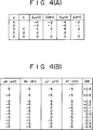
- the ROM 94 stores the following data every each combination of the slack filling frequency y and the ratio s of the total stopping machine frequency to the whole stopping machine frequency as a table shown in Fig. 4(A) according to the preceding control algorithms A10 through A13; a corrected value ⁇ k0 of the objective value in the average value of final release timing; a corrected value ⁇ k0 of the objective value in the dispersion of final release timing; a corrected value ⁇ t0 of the objective value in the average value of arrival timing; and a corrected value ⁇ t0 of the objective value in the dispersion of arrival timing.
- the ROM 94 receives the slack filling frequency y and the ratio s as address signals and then provides the correced values ⁇ k0, ⁇ k0, ⁇ t0, and ⁇ t0 corresponding to the received address signals through an output section 96 to an adder section 98 in the operation circuit 66.
- the adder circuit 98 adds the corrected values ⁇ k0, ⁇ k0, ⁇ t0, and ⁇ t0 to the corresponding objective values set in an objective value setter 64a of the setting circuit to calculate new objective values ⁇ k0, ⁇ k0, ⁇ t0, and ⁇ t0, respectively. Then, the adder circuit 98 provides the calculated objective values to a deviation calculating section 100 in the operation circuit 66.
- the deviation calculating section 100 calculates the average values ⁇ k and ⁇ t and the dispersion ⁇ k and ⁇ t of the corresponding timing on the basis of the final release timing and arrival timing which are provided from the running state detection, circuit 60a, and then calculates the deviations of the calculated values from the corresponding objective values ⁇ k0, ⁇ k0, ⁇ t0 and ⁇ t0 supplied from the adder section 98. Then, the deviation calculating section 100 provides the deviations thus obtained to the Read Only Memory, that is ROM 104 in the memory circuit 62 through a data converting section 102 in operation circuit 66.
- the ROM 104 stores the variation ⁇ M of the main pressure as a table shown in Fig. 4(B), for each combination of actual values, that is, a deviation ( ⁇ k- ⁇ k0) in the average value of final release timing; a deviation ( ⁇ k- ⁇ k0) in the dispersion of final release timing; a deviation ( ⁇ t- ⁇ t0) in the average value of arrival timing; and a deviation ( ⁇ t- ⁇ t0) in the dispersion of arrival timing.
- the ROM 104 receives the preceding deviations as a address signal and outputs the variation ⁇ M corresponding to the received address signal to an adder section 106 in the operation circuit 66.
- the adder section 106 adds the variation ⁇ M supplied from the ROM 104 to the present main pressure M supplied from a memory section 108 and then provides the added value to a limiter section 110 in the operation circuit 66.
- the limiter section 110 When the main pressure supplied from the adder section 106 is within the upper and lower limit values set in a limiting value setter 64b in the setting circuit, the limiter section 110 provides the main pressure from the adder section 106 to the pressure controller 68 in Fig. 1 through a line 112 as a new main pressure.
- the limiter section 110 outputs the upper limit value in case where the main pressure from the adder section 106 exceeds the upper limit value and the lower limit value in case where the preceding main pressure does not reach the lower limit value to the line 112 as a new main pressure, respectively.
- the pressure controller 68 adjusts the main pressure into a new value.
- weft inserting is carried out so as to satisfy any of the weft running state, the stopping state of the weaving machine and the fabric quality.
- the preceding process is also carried out every a predetermined pick number (or every a certain period of time).
- the new main pressure in the line 112 is stored in the memory section 108 so as to be used as a present main pressure in the subsequent correction process.
- An objective value set in an initial setter 64c of the setting circuit 64 is stored in the memory section 108 at the initiation of the operation for the apparatus for controlling weft inserting.
- the table shown in Fig. 4 is one of the embodiments, and the tables of the ROM 94 and ROM 104 are preferably subdivided within a permissible range of the memory capacity thereof.
- this preferred embodiment bases on the control algorithms A10 through A13 for correcting the objective value to be used in the automatic control system on the basis of the running information. Instead of this, it may base on the control algorithms A1 through A9 in combination with the running information, stopping machine information and quality information in similar to the preceding embodiment.
Abstract
Description
- This invention relates to a method and an apparatus for controlling weft inserting in an air jet loom, a water jet loom or the like, and more particularly, to a method and an apparatus for controlling weft inserting in a jet loom provided with an actuator for weft inserting.
- There has been proposed such a technique for controlling weft inserting so as to make fabrics get the predetermined qualities by correcting control conditions, that is, control parameter such as a pressure of the fluid jetted from a main nozzle (designated as "main pressure" in the present invention) or a pressure jetted from a subnozzle (designated as "subpressure" in the present invention) and then controlling actuators thereof on the basis of either one of running information such as the rotational angle (arrival angle) of a main shaft when a weft inserted into a warp shed reaches a predetermined position, stopping machine information such as the causes for stopping a weaving machine and the stop frequency thereof and quality information such as slack filling in woven fabrics and the frequency thereof.
- Now, the correction of the control conditions due to the running information is practised in short period (one period as the shortest cycle) during the operation of the weaving machine. On the other hand, since the correction of the control conditions due to the stopping machine information or quality information is practicable only when the weaving machine happens to stop or when the product quality is lowered, these corrections are practised in longer period. The directions to be corrected may sometimes be different depending on the running information, the stopping machine information and the quality information.
- Consequently, even though the corrections of the control conditions based on such a plurality of kinds of information may be merely employed simultaneously, the corrections due to these information are mutually cancelled and the corrections due to these information cannot be made use altogether. In other words, for example, even though the control conditions may be corrected on the basis of the stopping machine information after the stop of the weaving machine, the control conditions are thereafter returned to the control conditions before the stop of the weaving machine by the correction of the control conditions on the basis of the running information under the operation of the weaving machine.
- As described above, the techniques known per se only correct the control conditions using single information selected out of the running information, the stopping machine information and the quality information, as disclosed in Japanese Patent Public Disclosure (KOKAI) Nos. 56-107046 and 63-75149. Therefore, the control conditions could not be corrected due to a plurality of information, and an operator could not help relying on the manual corrections by the operator's professional feelings and experiences without relying on any automatic corrections for the purpose of these corrections.
- It is an object of the present invention to allow the weft inserting to be automatically controlled on the basis of a plurality of information without relying on the operator's professional feelings and experiences.
- A method for controlling weft inserting in the present invention comprises the steps of obtaining the control condition of an actuator for weft inserting on the basis of at least two kinds of information including running information representing the running state of weft, and stopping machine information representing the stopping state of a weaving machine or quality information representing the quality of a fabric quality, by use of at least one means selected out of the following means: a) an expert system constituted according to a control algorithm for weft inserting, b) a data table having data for weft inserting constituted according to the control algorithm for weft inserting, and c) an approximate expression by use of the information; and controlling the preceding actuator on the basis of the control condition thus obtained.
- An apparatus for controlling weft inserting in the invention comprises: information generation means for generating at least two kinds of information including running information representing the running state of weft, and stopping machine information representing the stopping state of a weaving machine or quality information representing the quality state of woven fabric; control condition-generating means selected out of a) an expert system constituted according to a control algorithm for weft inserting and for obtaining a control condition of an actuator for weft inserting on the basis of the informations, b) operating means provided with a data table having data for weft inserting and constituted according to a control algorithm for weft inserting and for obtaining a control condition of the actuator for weft inserting on the basis of the information and the preceding data; and c) operating means provided with memory means for storing a plurality of approximate expressions for calculating a control condition of the actuator for weft inserting using the informations, and for obtaining the preceding control condition using the preceding information and the preceding approximate expression; and means for controlling the preceding actuator on the basis of the obtained control condition.
- For example, in case where a control object is a main pressure, the control algorithm is composed of at least two kinds of information including running information with either stopping machine information or quality information in the following manner:
"Increase the main pressure, irrespective of leading end troubles, blow-by at the leading ends, barrel slippings, an average value and a dispersion of final release timing, and an average value and a dispersion of arrival timing, when the slack fillings often happen";
"Do not change the main pressure when no slack filling happens, but when leading end troubles, blow-by at the leading ends and barrel slippings often happen and when the slack fillings happened before."
"Decrease the main pressure, irrespective of leading end troubles, blow-by at the leading ends, barrel slipping, an average value and a dispersion of final release timing, and an average value and a dispersion of arrival timing, when no slack filing happens, but when leading end troubles, blow-by at the leading ends and barrel slippings often happen and when no slack fillings happened before." - The expert system obtains the control condition on the basis of a plurality of control rules using at least two kinds of information including running information with either stopping machine information or quality information, for example, in the following manner:
"Increase the main pressure by P, when a present slack filling frequency is often".
"Do not change the main pressure, when no slack filling happens, but when leading end troubles, blow-by at the leading ends and barrel slipping often happen and when the slack fillings happened before" and
"Decrease the main pressure by p, when no slack filling happens, but when leading end troubles, blow-by at the leading ends and barrel slippings often happen and when no slack filing happened before." In this case, the p may be a value for actually altering the pressure, a value for altering an objective value of the pressure, a value in common to the control rules or a different value every each control rule. - The control condition obtained from the control condition-generating means is supplied to control means such as a pressure controller from the control condition-generating means, and the control means controls an actuator such as a pressure regulator on the basis of the supplied control condition.
- According to the control method and the control apparatus which employ the expert system as the control condition-generating means, weft inserting can be controlled by using not only the running information under operation but also the stopping machine information or the quality information, and the weft inserting can be done under the satisfactory condition to these information.
- In case of using the operating means provided with the data table as the control condition-generating means, the operating means stores, for example, data such as a corrected content of the control object such as a main pressure or a corrected content of an objective value of the control object in the data table, every the combination of the running information with either the stopping machine information or the quality information, reads out the data of an address corresponding to the combination of the running information with either the stopping machine information or the quality information from the data table, and obtains a control condition on the basis of the read-out data. In this case, the data may be a value for actually altering the control condition such as a pressure, or a value for altering an objective value of the control condition. In any of the cases, the data is a value corresponding to the combination of these information.
- Weft inserting can be controlled by use of not only any running information under operation but also any stopping machine information or any quality information even by the control method and the control apparatus which utilize the operating means provided with the preceding data table as the control condition-generating means, and the weft inserting can also be done under the satisfactory condition to these information.
- For example, some weaving machines are actually operated according to a skillful operation to obtain the data such as the running information, the stopping machine information or the quality information, and the control condition for the actuator at that time. Then, the approximate expressions can be obtained from these data by a double regression analysis, for example. The approximate expressions thus obtained approximate to the control algorithm considered by the skillful operators.
- According to the control method and the control apparatus which employ the approximate expressions, weft inserting can also be controlled by using not only the running information under operation but also the stopping machine information or the quality information, and the weft inserting can be done under the satisfactory condition to these information.
- The foregoing and objects and features of the invention will become apparent from the following description of preferred embodiments of the invention with reference to the accompanying drawings, in which:
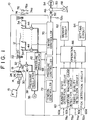
- Fig. 1 is a block diagram showing an electric circuit of a weaving machine provided with a weft inserting control apparatus as a preferred embodiment of the present invention;
- Fig. 2 is a block diagram showing an electric circuit of a weft inserting control apparatus as another embodiment of the present invention;
- Fig. 3 is a block diagram showing an electric circuit of a weft inserting control apparatus as a further embodiment of the present invention; and
- Fig. 4 is a view showing a data table used in the weft inserting control apparatus of Fig. 3 as a preferred embodiment of the present invention.
- Referring now to Fig. 1, a
weaving machine 10 is a jet loom of either an air or water type, and includes a drum type lengthmeasuring storage unit 14 for aweft 12. Theweft 12 is rolled around aweft package 16. Theweft 12 is also supplied from theweft package 16 to aweft inserting unit 18 known per se through the lengthmeasuring storage unit 14 and is inserted in awarp shed 22 from the preceding weft inserting unit. - At the measurement time, the
weft 12 is prevented 12 is prevented from the release from a length measuring-and-storage drum 28 by anengagement pin 26 having the top portion operated by anelectromagnetic solenoid 24, and is stored while being rolled by a predetermined length around the circumferential surface of thedrum 28 through the rotation of ayarn guide 30. - On the other hand, at the weft inserting time, the
weft 12 is released from thedrum 28 by the release of thepin 26, and is cut off after theweft 12 is ejected from amain nozzle 32 of theweft inserting unit 18 together with fluid so as to be inserted into thewarp shed 22. Theweft inserting unit 18 includes a plurality ofsubnozzles 34 for jetting the fluid to advance theweft 12 to a predetermined direction at the weft inserting time. - Working fluid of a
pressure source 36 is supplied to themain nozzle 32 through apressure regulator 38 and aswitching valve 40. On the other hand, the working fluid of thepressure source 36 is supplied to eachsubnozzle 34 through apressure regulator 42 and a correspondedswitching valve 44. - The
weaving machine 10 also includes amotor 48 for amain shaft 46 for driving a reed. The rotation of themotor 48 is transmitted from aconnection mechanism 50 to themain shaft 46. Themain shaft 46 is attached with both anencoder 52 for generating a rotational angle signal corresponding to the rotational angle of the main shaft and anelectromagnetic brake 54 for themain shaft 46. The length measuringstorage unit 14 and theweft inserting unit 18 are driven together with healds and reed in synchronism with the rotation of themain shaft 46. - A weft inserting control apparatus for the
weaving machine 10 includes adetection circuit 60 for detecting operating information with respect to the weft inserting of the weaving machine, amemory circuit 62 for storing various information, data or the like, asetting circuit 64 for manually setting various information, anoperation circuit 66 for obtaining a control condition on the basis of the information and data from each of the precedingcircuits 60 through 64, apressure controller 68 for controlling thepressure regulators operation circuit 66, atiming controller 70 for driving theswitching valves electromagnetic solenoid 24 on the basis of the signal supplied from theoperation circuit 66, and atension controller 72 for controlling a warp tension mechanism (not shown) on the basis of the signal supplied from theoperation circuit 66. - The operating information includes running information, stopping machine information, quality information and a pick number. Therefore, the respective output signals 74a, 76a, 78a and 52a of a
first detector 74 for detecting that theweft 12 is inserted up to a final position thereof, asecond detector 76 for detecting that theweft 12 is inserted up to not less than a permissible position thereof, arelease sensor 78 for detecting that theweft 12 is released from the lengthmeasuring storage unit 14 and anencoder 52 are supplied to thedetection circuit 60. The output signal 78a of therelease sensor 78 is also supplied to thetiming controller 70. - The
detection circuit 60 is provided with acircuit 60a for detecting the weft running state, acircuit 60b for detecting the cause of the stopping of the weaving machine, acircuit 60c for detecting a fabric quality and acircuit 60d for detecting picks or the like. - As for the running information, for example, use is made of an average value and a dispersion of weft running timing such as so-called release timing like a rotational angle (release angle) of the main shaft when the weft at a predetermined winding stitch is released from the length measuring storage unit and so-called arrival timing like a rotational angle (arrival angle) of the main shaft when a leading end portion of the weft reaches a predetermined position.
- As for the running timing, at least one selected from the following can be used, that is:
- * so-called "final release timing" such as rotational angle of the main shaft when the final roll of the weft is released from the length measuring storage unit;
- * so-called "final arrival timing" such as a rotational angle of the main shaft when leading end portion of the weft reaches the final position; and
- * so-called "intermediate arrival timing" such as a rotational angle of the main shaft when the weft reaches a predetermined position between the length measuring storage unit and the final position.
- As for a specific value of an average value of the running timing, for example, at least one selected from the following can be used, that is:
- * an average value itself of running timing;
- * a difference between an average value of running timing and an objective value thereof, that is, an average value error;
- * an average value itself of the maximum or minimum value in running timing; and
- * a difference between an average value of the maximum or minimum value in running timing and an objective value thereof.
- As for a specific value of a dispersion of the running timing, for example, at least one selected from the following can be used, that is:
- * a dispersion itself of running timing;
- * a difference between a dispersion of running timing and an objective value thereof, that is, a dispersion error;
- * a dispersion itself of the maximum or minimum value in running timing; and
- * a difference between a dispersion of the maximum or minimum value in running timing and an objective value thereof.
- The stopping machine information is a stopping machine frequency every each cause of the stopping machine. As for a stopping machine cause, there are a so-called "H1 stop" due to the fact that the
weft 12 cannot be detected by thefirst detector 74 and a so-called "H2 stop" due to the fact that theweft 12 can be detected by thesecond detector 76. - As for the causes for H1 stop and H2 stop, for example, the following will be listed.
-
- * leading end troubles
- * Vent pick
- * Warp looping
- * Length measuring mistake
- * Blow-by at the leading ends
- * Cutting mistake
- * Stop by running out
-
- * Barrel slipping
- * Run out of constraint
- As for the quality information, the following will be listed.
- * Slack filling
- * Kinky thread
- * fluff
- In case where there are sensors for enabling to automatically detect individual phenomenon, the stopping machine information and the quality information can, however, be obtained by the input of these signals, and in case where these sensors are not available, the preceding information can be obtained by the manual input on the basis of the operator's judgement. Furthermore, the quality information is inputted depending on the sensor or the operator's judgement during the operation of the weaving machine or after the machine stops.
- As for the control conditions, that is, control parameters, for example, at least one selected from the following can be used, that is:
- * Main pressure;
- * Subpressure;
- * Timing at the start of a fluid ejection from the main nozzle;
- * Timing at the end of a fluid ejection from the main nozzle;
- * Timing at the start of a fluid ejection from the subnozzle;
- * Timing at the end of a fluid ejection from the subnozzle;
- * Timing at the start of a weft release by the length measuring storage unit;
- * Timing at the end of a weft release by the length measuring storage unit; and
- * Start time for weft inserting, that is, start time for weft picking. Now, the start time for weft inserting means what is defined by both the timing at the start of a fluid ejection from the main nozzle and the timing at the start of a weft release from the length measuring storage unit, and is always a parameter when the start time for weft inserting is set so that both of such timings may be altered interlockingly.
- The kinds of threads, the representative values (average value, median, mode, fastest value, latest value or the like) of the objective values in the control parameters, the dispersion (standared deviation, range or the like) of the objective values in the control parameters, the sample number (pick number, woven length, time) and the upper or lower limit value of operation content are all set in the
setter 64. - Any of corrected values of a plurality of control rules and the control conditions and the approximate expressions are stored in the
memory circuit 62, depending on selecting either of the expert system, the data table and the approximate expressions for the control conditions. The corrected values of a plurality of control rules and the control conditions are prepared according to a predetermined control algorithm. On the other hand, the approximate expressions are obtained by causing the weaving machine to be actually operated by a skillful operator to give data of the running information, stopping machine information or quality information, the control conditions for the actuator or the like at that time and then making the double regression analysis from the preceding data. - As described in prior art, however, various automatic control systems on the basis of the running information are generally attached to the weaving machine as the control during the operation of the weaving machine. For example, as for the automatic control system, there are some systems for automatically varying the pressure and/or the jet timing so that an angle for weft to reach a weft sensor provided at a predetermined position in the weft inserting path may become constant. If an automatic control system on the basis of the stopping machine information or the quality information made after the weaving machine stops is merely added to this automatic control system, both of these automatic control systems interfere with each other and the functions thereof cannot be activated together.
- In the present invention, now, this problem has been solved by the following two techniques, respectively.
- (1) The automatic control system on the basis of the running information is combined with the automatic control system on the basis of the stopping machine information to prepare a control algorithm in which the running information, the stopping machine information and the quality information are combined with one another, and according to this control algorithm, the control conditions of a pressure, timing or the like are varied.
- (2) The automatic control system on the basis of the running information is worked as it is, and the control algorithm on the basis of the stopping machine information and the quality information does not vary the control conditions of the pressure or the like, but corrects an objective value to be used in the automatic control system on the basis of the running information.
- According to the above description (1), any control conditions are corrected on the basis of the combined control algorithm with the running information, the stopping machine information and the quality information, and consequently, a control can be performed under the satisfactory condition to each information.
- According to the above description (2), the objective value to be used in the existing automatic control system on the basis of the running information while using this automatic control system as it is, is corrected by the automatic control system on the basis of the stopping machine information and the quality information, and consequently, a control is performed under the satisfactory condition to each information without any mutual interferences in the automatic control systems.
- The following will show one embodiment of the control algorithm on the basis of the above description (1). In addition, the following control algorithm is available for the case where the control condition is a main pressure, but it may be other control conditions in the above description or the combinations thereof.
- A1: Increase the main pressure, independently of any leading end troubles, a blow-by at the leading ends, a barrel slipping, an average value and a dispersion of final release timing and an average value and a dispersion of arrival timing, when there are slack fillings.
- A2: Do not change the main pressure, when there is no slack filling, and any leading end troubles, blowby at the leading ends and barrel slippings often happen but when there were slack fillings before.
- A3: Decrease the main pressure, independently of an average value and a dispersion of final release timing and an average value and a dispersion of arrival timing, when there is no slack filling, any leading end troubles, blow-by at the leading ends and barrel slippings often happen and there was no slack filling before.
- A4: Do not change the main pressure, when there is no slack filling, and any leading end troubles, blowby at the leading ends and barrel slippings happen a little, but when there were slack fillings before or any leading end troubles, blow-by at the leading ends and barrel slippings did not happen before.
- A5: Increase the main pressure, when there is no slack filling, and any leading end troubles, blow-by at the leading ends and barrel slippings happen a little, but when there was no slack filling before, any leading end troubles, blow-by at the leading ends and barrel slippings happened a little before and an average value of final release timing is late or a dispersion thereof is large.
- A6: Increase the main pressure, when there is and was no slack filling and any leading end troubles, blowby at the leading ends and barrel slippings happen a little and happened a little before, but when an average value of final release timing is fast, a dispersion of final release timing is small, an average value of arrival timing is late and a dispersion of arrival timing is large.
- A7: Increase the main pressure, when there is and was no slack filling and any leading end troubles, blowby at the leading ends and barrel slippings happen a little and happened a little before, but when an average value of final release timing is fast, a dispersion of final release timing is small, an average value of arrival timing is delayed and a dispersion of arrival timing is small.
- A8: Do not change the main pressure, when there is and was no slack filling and any leading end troubles, blow-by at the leading ends and barrel slippings happen a little and happened a little before, but when an average value of final release timing is fast, a dispersion of final release timing is small, an average value of arrival timing is fast and a dispersion of arrival timing is large.
- A9: Decrease the main pressure, when there is and was no slack filling and any leading end troubles, blowby at the leading ends and barrel slippings happen a little and happened a little before, but when an average value of final release timing is fast, a dispersion of final release timing is small, an average value of arrival timing is fast and a dispersion of arrival timing is small.
- In the control algorithm as described above, since the slack fillings are problem related to fabric quality, the control condition is corrected if a slack filling happens even only at one time. On the other hand, in case of the leading end troubles, blow-by at the leading ends and barrel slippings, the control condition is corrected depending on the generation frequencies thereof. It can be judged by comparing the generation ratios between the generation times during a certain period of time (hour, pick number and woven length) and each stopping machine cause to the total stopping machine times during the certain period of time with the limiting values thereof whether the frequencies are "often" or "small". The word "before" can mean an arbitrary time in the past, and for example, it can be set as a measure of the time while a piece of weft package is consumed. Furthermore, the definitions such as "small", "large", "fast", and "late" can be standardized using the corresponding objective values and limiting values.
- Now, on the basis of the above description (2), one embodiment of the control algorithm for correcting actual control information by correcting the objective values of the control conditions will be shown in the following. This is an embodiment when the automatic control system on the basis of the running information controls the main pressure so that the running timing of a weft may be arranged within an objective value. The parentheses show the corrected state of the resulting main pressure.
- A10: Quicken the objective value in the average value of arrival timing. (Increase the main pressure), when there were slack fillings.
- A11: Delay the objective values in the average values of final release timing and arrival timing and enlarge the objective values of both dispersion (Decrease the main pressure.), when any leading end troubles often happen.
- A12: Delay the objective values in the average values of final release timing and arrival timing and enlarge the objective values of both dispersions (Decrease the main pressure.), when any blow-by at the leading ends often happens.
- A13: Delay the objective values in the average values of final release timing and arrival timing and enlarge the objective values of both dispersions (Decrease the main pressure.), when any barrel slippings often happen.
- The control algorithm as described above can also be prepared with respect to the preceding other control conditions, and it may be prepared using other information as well.
- In case where the weft inserting control apparatus uses the expect system, a plurality of control rules prepared according to the preceding control algorithm are stored in the
memory circuit 62. On the other hand, in case where the weft inserting control apparatus uses the data table, a plurality of data for weft inserting prepared according to the preceding control algorithm are stored in the memory circuit. Furthermore, in case where the weft inserting control apparatus uses the approximate expression, the approximate expression is stored in thememory circuit 62. - Now, a specific method for controlling weft inserting will be explained in the following. The following explanation relates to the case of controlling the main pressure, but it can also control the case by other control conditions such as the subpressure, action timing of the engagement pin or the like in a similar manner. Other information may be used as well.
- First of all, referring now to Fig. 1, the detailed description of a control method of the main pressure by the approximate expression will be given in the following. The following approximate expression for obtaining a corrected value of the main pressure is stored in the
memory circuit 62. - ΔM = f(µk - µk0, σk- σk0, µt - µt0, σt -σt0, y, s) wherein,
- µk
- : an average value of final release timing,
- σk
- : a dispersion of final release timing,
- µt
- : an average value of arrival timing,
- σt
- : a dispersion of arrival timing,
- µk0
- : an objective value in the average value of final release timing,
- σk0
- : an objective value in the dispersion of final release timing,
- µt0
- : an objective value in the average value of arrival timing,
- σt0
- : an objective value in the dispersion of arrival timing,
- y
- : a frequency of present slack filling,
- ΔM
- : a corrected value for main pressure, and
- s
- : a ratio of total stopping machine frequencies due to leading end troubles, blow-by at the leading ends and barrel slippings to total stopping machine frequencies.
- The preceding approximate expression can be obtained by actually operating the weaving machine, experimentally recording each value of input variables at that time and the corrected content by a skillful operator, and making a double regression analysis using these values.
- The objective value µkO in the average value of final release timing, the objective value σk0 in the dispersion of final release timing, the objective value µt0 in the average value of arrival timing, and the objective value σt0 in the dispersion of arrival timing are preliminarily set in the
setting circuit 64, respectively. - The
operation circuit 66 calculates the average value µk and the dispersion σk of final release timing and the average value µt and the dispersion σt of arrival timing on the basis of the final release timing and the arrival timing which are outputted from the runningstate detection circuit 60a. Theoperation circuit 66 also calculates a total value due to the leading end troubles, blow-by at the leading ends and barrel slippings, that is, a total stopping machine frequency, a sum of the total individual cause stopping machine frequency, that is, a whole stopping machine frequency, and a ratio s of the total stopping machine frequency to the whole stopping machine frequency on the basis of an individual cause stopping machine signal which is outputted from the stopping machinecause detection circuit 60b. Furthermore, theoperation circuit 66 calculates a slack filling frequency y on the basis of a slack filling signal which is outputted from a fabricquality detection circuit 60c, and further calculates a pick number (weft inserting frequency) on the basis of a detection signal which is outputted from thepick detection circuit 60d. - By substituting the values of µk, µk0, σk, σk0, µt, µt0, σt, σt0, y and s into the preceding approximate expression every time when each pick number reaches a set value in the
setting circuit 64, theoperation circuit 66 calculates a corrected content ΔM of the main pressure and adds the calculated corrected content to the present main pressure to thereby give a new main pressure. - The
operation circuit 66 provides the calculated main pressure in apressure controller 68 as it is in a form of a new main pressure in case where the new main pressure is within the upper and lower limit values set in thesetting circuit 64, while theoperation circuit 66 provides a limiting value in thepressure controller 68 as a new main pressure in case where the calculated main pressure is at the outside of the upper and lower limit values. - Accordingly, the
pressure controller 68 adjusts the main pressure into a new value. As a result, the weft inserting is made so that satisfy any of the running state, stopping state of the weaving machine and fabric quality thereof. The preceding process is carried out every each predetermined pick number (or every a certain period of time.) - The preceding approximate expression may be calculated every each kind of thread. Each coefficient for each kind of thread is defined as follows:

- According to the control method by use of the preceding approximate expression, the storage capacity of the memory circuit becomes remarkably small.
- Referring now to Fig. 2, the detailed description of a method for controlling weft inserting by use of the expert system will be given in the following.
- The
operation circuit 66 comprises acircuit 80 for statistically processing the output signals received from the runningstate detection circuit 60a, the stopping machinecause detection circuit 60b and the fabricquality detection circuit 60c, acounter 82 for counting the output signal from thepick detection circuit 60d until the output signal becomes equal to the value set in thesetting circuit 64, aninference engine 84 for inferring correction values for control conditions on the basis of a plurality of control rules stored in thememory circuit 62, and acontroller 86 for calculating renewed control conditions on the basis of the output signals from thecircuits - An embodiment of the control rules R1 through R9 in case of setting the control condition as the main pressure will be shown in the following. The control rules R1 through R9 correspond to the control algorithms A1 through A9, respectively.
- R′ : If any leading end troubles, blow-by at the leading ends and barrel slippings happen a little, then s=0, and otherwise s=1.
- R˝ ˝ If any leading end troubles, blow-by at the leading ends and barrel slippings previously happened a little, then s′= 0, and otherwise s′= 1.
- R1
- : If y>0 then ΔM= +p.
- R2
- : If y=0, s=1 and y′>0, then ΔM=0.
- R3
- : If y=0, s=1 and y′=0, then ΔM=-p.
- R4
- : If y=0, s=0 and beside y′>0 or s′=0, then ΔM=0.
- R5
- : If y=0, s=0, y′=0, s′=0 and besides µk > µk0 or σk > σk0, then ΔM= +p.
- R6
- : If y=0, s=0, y′=0, s′=0, µk < µk0, and σk< σk0, besides µt > µt0 and σt > σt0, then ΔM= +p.
- R7
- : If y=0, s=0, y′-0, s′=0, µk < µk0, and σk< σk0, besides µt>µt0 and σt<σt0, then ΔM= +p.
- R8
- : If y=0, s=0, y′=0, s′=0, µk<µk0, and σk< σk0, besides µt < µt0 and σt > σt0, then ΔM=0.
- R9
- : If y=0, s=0, y′=0, s′=0, µk < µk0, and σk<σk0, besides µt < µt0 and σt < σt0, then ΔM= -p.
- In the preceding control rules R1 through R9, the symbols indicate as follows:
- µk
- : an average value of final release time,
- σk
- : a dispersion of final release timing,
- µt
- : an average value of arrival timing,
- σt
- : a dispersion of arrival timing,
- σk0
- : a threshold in the average value of final release timing,
- µk0
- : a threshold in the dispersion of final release timing,
- µt0
- : a threshold in the average value of arrival timing,
- σt0
- : a threshold in the dispersion of arrival timing,
- y
- : a present slack filling frequency,
- y′
- : a previous slack filling frequency,
- ΔM
- : a corrected value for the main pressure,
- p
- : a variation quantity in the main pressure preliminarily given,
- s
- : a ratio of a total stopping machine frequency due to the leading end troubles, blow-by at the leading ends and barrel slippings to a present whole stopping machine frequency, and
- s′
- : a ratio of a total stopping machine frequency due to the leading end troubles, blow-by at the leading ends and barrel slippings to a previous whole stopping machine frequency.
- The average value and the dispersion µk and σk of final release timing and the average value and the dispersion µt and σt of arrival timing in the preceding control rules R1 through R9 are calculated in the
statistical processing circuit 80 on the basis of the final release timing and arrival timing which are generated from the runningstate detection circuit 60a, respectively. - Also, the total stopping machine frequency due to the leading troubles, blow-by at the leading ends and barrel slippings, the whole stopping machine frequency, the ratio s of the total stopping machine frequency to the present whole stopping machine frequency and the ratio s′ of the total stopping machine frequency to the previous whole stopping machine frequency, respectively, are calculated in the
statistical processing circuit 80 on the basis of the individual cause stopping machine signals generated from the stopping machinecause detection circuit 60b. Furthermore, the present slack filling frequency y and the previous slack filling frequency y′ are calculated in thestatistical processing circuit 80 on the basis of the slack filling signals generated from the fabricquality detection circuit 60c. - The threshold µk0 in the average value of final release timing, the threshold σk0 in the dispersion of final release timing, the threshold µt0 in the average value of arrival timing, the threshold σt0 in the dispersion of arrival timing, and the variation p of the main pressure respectively, are preliminarily set in the
setting circuit 64. These various thresholds can be used which are same as various objective values used in the preceding embodiment on the basis of the previous approximate expression. - Whenever the output value from the
counter 82 becomes equal to the previously set value in thesetting circuit 64, thecontroller 86 receives the data from thestatistical processing circuit 80 and provides the received data to theinference engine 84, together with the right of execution. Then, theinference engine 84 infers the corrected value ΔM of the main pressure on the basis of the received data, and the control rules R′, R˝ and R1 through R9 to provide a resultant corrected value ΔM to thecontroller 86. - The
controller 86 calculates a renewed present value for the main pressure by adding the corrected value ΔM thus inferred to the present main pressure value. If the resultant value for the main pressure is within the upper and lower limit values, then thecontroller 86 provides the resultant value as a renewed present value for the main pressure through aline 88 to thepressure controller 68 in Fig. 1. If the resultant value for the main pressure is at the outside of the upper and lower limit values, then the limiting value is provided as a renewed value for the main pressure to thepressure controller 68 through theline 88. - Now, the
pressure controller 68 adjusts the main pressure into the renewed value, and as a result, the weft inserting can be performed under the satisfactory condition to any of the running state of the weft, the stopping state of the weaving machine and the fabric quality. The preceding process in this case is carried out every a predetermined pick number (or every a certain period of time). - In this preferred embodiment, the main pressure itself to be altered is to be determined on the basis of the control algorithms A1 through A9 in a combination with the running information, stopping machine information and quality information. Instead of these algorithms, use may be made of the control algorithms A10 through A13 for correcting the objective value used in the automatic control system on the basis of the running information.
- Referring now to Figs. 3 and 4, a method for controlling weft inserting by use of the data table will be explained in the following. This preferred embodiment bases on the preceding control algorithms A10 through A13, adopts what can correct the main pressure so that various running timing may be accommodated within the objective values as the automatic control system on the basis of the running information, and corrects the objective values to be used in this automatic control system on the basis of the stopping machine information and the quality information.
- The output signals from the stopping machine
cause detection circuit 60b and the fabricquality detection circuit 60c are provided todata converting section operation circuit 66. On the basis of the individual cause stopping machine signal generated from the stopping machinecause detection circuit 60b, thedata converting section 90 calculates both the total stopping machine frequency due to the leading end troubles, blow-by at the leading ends and barrel slippings and the whole stopping machine frequency to obtain the ratio s of the total stopping machine frequency to the whole stopping machine frequency, and provides the value thus obtained to a Read Only Memory, that is, aROM 94 in thememory circuit 62. On the other hand, thedata converting section 92 calculates the slack filling frequency y on the basis of the slack filling signals received from the fabricquality detection circuit 60c to provide the calculated value y to theROM 94. - The
ROM 94 stores the following data every each combination of the slack filling frequency y and the ratio s of the total stopping machine frequency to the whole stopping machine frequency as a table shown in Fig. 4(A) according to the preceding control algorithms A10 through A13;
a corrected value Δµk0 of the objective value in the average value of final release timing;
a corrected value Δσk0 of the objective value in the dispersion of final release timing;
a corrected value Δµt0 of the objective value in the average value of arrival timing; and
a corrected value Δσt0 of the objective value in the dispersion of arrival timing. - Also, the
ROM 94 receives the slack filling frequency y and the ratio s as address signals and then provides the correced values Δµk0, Δσk0, Δµt0, and Δσt0 corresponding to the received address signals through anoutput section 96 to anadder section 98 in theoperation circuit 66. - The
adder circuit 98 adds the corrected values Δµk0, Δσk0, Δµt0, and Δσt0 to the corresponding objective values set in an objective value setter 64a of the setting circuit to calculate new objective values µk0, σk0, µt0, and σt0, respectively. Then, theadder circuit 98 provides the calculated objective values to adeviation calculating section 100 in theoperation circuit 66. - The
deviation calculating section 100 calculates the average values µk and µt and the dispersion σk and σt of the corresponding timing on the basis of the final release timing and arrival timing which are provided from the running state detection,circuit 60a, and then calculates the deviations of the calculated values from the corresponding objective values µk0, σk0, µt0 and σt0 supplied from theadder section 98. Then, thedeviation calculating section 100 provides the deviations thus obtained to the Read Only Memory, that isROM 104 in thememory circuit 62 through adata converting section 102 inoperation circuit 66. - The
ROM 104 stores the variation ΔM of the main pressure as a table shown in Fig. 4(B), for each combination of actual values, that is,
a deviation (µk- µk0) in the average value of final release timing;
a deviation (σk- σk0) in the dispersion of final release timing;
a deviation (µt- µt0) in the average value of arrival timing; and
a deviation (σt- σt0) in the dispersion of arrival timing. - In addition, the
ROM 104 receives the preceding deviations as a address signal and outputs the variation ΔM corresponding to the received address signal to anadder section 106 in theoperation circuit 66. - The
adder section 106 adds the variation ΔM supplied from theROM 104 to the present main pressure M supplied from amemory section 108 and then provides the added value to alimiter section 110 in theoperation circuit 66. - When the main pressure supplied from the
adder section 106 is within the upper and lower limit values set in a limitingvalue setter 64b in the setting circuit, thelimiter section 110 provides the main pressure from theadder section 106 to thepressure controller 68 in Fig. 1 through aline 112 as a new main pressure. Thelimiter section 110, however, outputs the upper limit value in case where the main pressure from theadder section 106 exceeds the upper limit value and the lower limit value in case where the preceding main pressure does not reach the lower limit value to theline 112 as a new main pressure, respectively. - Accordingly, the
pressure controller 68 adjusts the main pressure into a new value. As a result, weft inserting is carried out so as to satisfy any of the weft running state, the stopping state of the weaving machine and the fabric quality. The preceding process is also carried out every a predetermined pick number (or every a certain period of time). - The new main pressure in the
line 112 is stored in thememory section 108 so as to be used as a present main pressure in the subsequent correction process. An objective value set in aninitial setter 64c of the settingcircuit 64 is stored in thememory section 108 at the initiation of the operation for the apparatus for controlling weft inserting. - The table shown in Fig. 4 is one of the embodiments, and the tables of the
ROM 94 andROM 104 are preferably subdivided within a permissible range of the memory capacity thereof. - Incidentally, this preferred embodiment bases on the control algorithms A10 through A13 for correcting the objective value to be used in the automatic control system on the basis of the running information. Instead of this, it may base on the control algorithms A1 through A9 in combination with the running information, stopping machine information and quality information in similar to the preceding embodiment.
Claims (8)
- A method for controlling weft inserting in a jet loom (10), comprising the steps of:
calculating the control conditions of an actuator for weft inserting by using at least one means selected out of:a) an expert system constituted according to control algorithms for weft inserting;b) a data table having data for weft inserting and constituted according to control algorithms for weft inserting; andc) an approximate expression,on the basis of at least two kinds of information including running information representing the running state of a weft, and stopping machine information representing the stopping state of a weaving machine or quality information representing the state of a woven fabric quality; and
controlling said actuator on the basis of the calculated control conditions. - An apparatus for controlling weft inserting in a jet loom (10), comprising:
information generation means for generating at least two kinds of information including running information representing the running state of a weft, and stopping machine information representing the stopping state of a weaving machine or quality information representing the state of a woven fabric quality;
control condition-generating means selected out of:a) an expert system (66) constituted according to the control algorithms for weft inserting and for calculating the control conditions of an actuator for weft inserting on the basis of at least two kinds of said information;b) operating means (66) provided with a data table having data for weft inserting and constituted according to the control algorithms for weft inserting and for calculating the control conditions of the actuator for weft inserting on the basis of said at least two kinds of information and said data; andc) operating means (66) provided with memory means for storing a plurality of approximate expressions for calculating the control conditions of the actuator for weft inserting using said at least two kinds of information and for calculating said control conditions using said at least two kinds of information and said approximate expression; andmeans (68,70,72) for controlling said actuator on the basis of the calculated control conditions. - A method for controlling weft inserting in a jet loom (10), comprising the steps of:
calculating the control conditions of an actuator for weft inserting by use of an expert system constituted according to the control algorithms for weft inserting on the basis of at least two kinds of information including running information representing the running state of a weft, and stopping machine information representing the stopping state of a weaving machine or quality information representing the state of woven fabric quality; and
controlling said actuator on the basis of the calculated control conditions. - An apparatus for controlling weft inserting in a jet loom, comprising:
information generation means (60) for generating at least two kinds of information including running information representing the running state of a weft, and stopping machine information representing the stopping state of a weaving machine or quality information representing the state of woven fabric quality;
control condition-generating means (66) using an expert system constituted according to the control algorithms for weft inserting and for calculating the control conditions of an actuator for weft inserting on the basis of said at least two kinds of information; and
means (68,70,72) for controlling said actuator on the basis of the calculated control conditions. - A method for controlling weft inserting in a jet loom (10), comprising the steps of:
calculating the control conditions of an actuator for weft inserting using a data table having data for weft inserting and constituted according to the control algorithms for weft inserting on the basis of at least two kinds of information including running information representing the running state of a weft, and stopping machine information representing the stopping state of a weaving machine or quality information representing the state of a woven fabric quality; and
controlling said actuator on the basis of the calculated control conditions. - An apparatus for controlling weft inserting in a jet loom (10), comprising:
information generation means (60) for generating at least two kinds of information including running information representing the running state of a weft, and stopping machine information representing the stopping state of a weaving machine or quality information representing the state of a woven fabric quality;
control condition-generating means (66) using operating means provided with a data table having data for weft inserting constituted according to the control algorithms for weft inserting and for calculating the control conditions of an actuator for weft inserting on the basis of said at least two kinds of information and said data; and
means (68,70,72) for controlling said actuator on the basis of the calculated control conditions. - A method for controlling weft inserting in a jet loom (10), comprising the steps of:
calculating the control conditions of an actuator for weft inserting using an approximate expression on the basis of at least two kinds of information including running information representing the running state of a weft, and stopping machine information representing the stopping state of a weaving machine or quality information representing the state of a woven fabric quality; and
controlling said actuator on the basis of the calculated control conditions. - An apparatus for controlling weft inserting in a jet loom (10), comprising:
information generation means (60) for generating at least two kinds of information including running information representing the running state of a weft, and stopping machine information representing the stopping state of a weaving machine or quality information representing the state of a woven fabric quality;
control condition-generating means (66) using operating means provided with memory means for storing a plurality of approximate expressions for calculating the control conditions of an actuator for weft inserting by use of said at least two kinds of information and for calculating said control conditions by use of said at least two kinds of information and said approximate expressions; and
means (68,70,72) for controlling said actuator on the basis of the calculated control conditions.
Applications Claiming Priority (2)
| Application Number | Priority Date | Filing Date | Title |
|---|---|---|---|
| JP193566/91 | 1991-07-09 | ||
| JP19356691A JP3606330B2 (en) | 1991-07-09 | 1991-07-09 | Jet loom weft insertion control method and apparatus |
Publications (2)
| Publication Number | Publication Date |
|---|---|
| EP0522846A1 true EP0522846A1 (en) | 1993-01-13 |
| EP0522846B1 EP0522846B1 (en) | 1997-10-29 |
Family
ID=16310153
Family Applications (1)
| Application Number | Title | Priority Date | Filing Date |
|---|---|---|---|
| EP92306280A Expired - Lifetime EP0522846B1 (en) | 1991-07-09 | 1992-07-08 | Method and apparatus for controlling weft inserting in jet loom |
Country Status (5)
| Country | Link |
|---|---|
| US (1) | US5320142A (en) |
| EP (1) | EP0522846B1 (en) |
| JP (1) | JP3606330B2 (en) |
| KR (1) | KR930002570A (en) |
| DE (1) | DE69222896T2 (en) |
Cited By (4)
| Publication number | Priority date | Publication date | Assignee | Title |
|---|---|---|---|---|
| DE4226693A1 (en) * | 1991-08-12 | 1993-02-18 | Nissan Motor | Computer control of airjet loom - has data store of unwinding behaviour of weft yarn supply to set up optimum processing conditions |
| EP0962566A2 (en) * | 1998-06-02 | 1999-12-08 | Lindauer Dornier Gesellschaft M.B.H | Method for controlling weft releasing and stopping operation on yarn storage devices in looms |
| EP1428917A2 (en) * | 2002-12-10 | 2004-06-16 | Tsudakoma Kogyo Kabushiki Kaisha | Method of calculating timing of weft picking and method of setting weft inserting condition in fluid jet loom |
| WO2006114187A1 (en) * | 2005-04-25 | 2006-11-02 | Picanol N.V. | Method for introducing a weft thread in a weaving machine |
Families Citing this family (6)
| Publication number | Priority date | Publication date | Assignee | Title |
|---|---|---|---|---|
| DE59510865D1 (en) * | 1994-09-16 | 2004-04-01 | Picanol Nv | Throttle valve for compressed air and method for calibrating the throttle valve |
| EP0708189B1 (en) * | 1994-10-17 | 2000-12-27 | Sulzer Textil AG | Method of controlling yarn tension |
| US8165712B2 (en) * | 2006-05-04 | 2012-04-24 | Textilma Ag | Loom, in particular a ribbon loom |
| CN101135082B (en) * | 2007-06-28 | 2010-06-23 | 江苏万工科技集团有限公司 | Air-jet loom beating-up anteversion angle regulating device |
| US9330148B2 (en) * | 2011-06-30 | 2016-05-03 | International Business Machines Corporation | Adapting data quality rules based upon user application requirements |
| JP6447533B2 (en) * | 2016-02-19 | 2019-01-09 | 株式会社豊田自動織機 | Weft insertion control method and weft insertion control apparatus for air jet loom |
Citations (4)
| Publication number | Priority date | Publication date | Assignee | Title |
|---|---|---|---|---|
| GB2067606A (en) * | 1980-01-23 | 1981-07-30 | Sulzer Ag | Looms |
| JPS6375149A (en) * | 1986-09-13 | 1988-04-05 | 株式会社豊田自動織機製作所 | Weaving condition control method in loom |
| EP0382490A2 (en) * | 1989-02-08 | 1990-08-16 | Tsudakoma Kogyo Kabushiki Kaisha | Method for controlling weaving machine and apparatus therefor |
| US4967806A (en) * | 1989-04-05 | 1990-11-06 | Nissan Motor Co., Ltd. | Automatic weft picking control system for fluid jet loom |
Family Cites Families (4)
| Publication number | Priority date | Publication date | Assignee | Title |
|---|---|---|---|---|
| JPH0639735B2 (en) * | 1984-07-24 | 1994-05-25 | 日産自動車株式会社 | Fluid ejection loom controller |
| JPH0759774B2 (en) * | 1986-10-04 | 1995-06-28 | 津田駒工業株式会社 | Automatic weft insertion adjustment method for shuttleless loom |
| JP2516353B2 (en) * | 1987-01-30 | 1996-07-24 | 津田駒工業株式会社 | Side-loading control device for air-loom loom |
| JP2849422B2 (en) * | 1989-12-28 | 1999-01-20 | 津田駒工業株式会社 | Method and apparatus for controlling injection pressure of weft insertion nozzle of loom |
-
1991
- 1991-07-09 JP JP19356691A patent/JP3606330B2/en not_active Expired - Fee Related
-
1992
- 1992-07-04 KR KR1019920011907A patent/KR930002570A/en not_active Application Discontinuation
- 1992-07-07 US US07/909,629 patent/US5320142A/en not_active Expired - Fee Related
- 1992-07-08 DE DE69222896T patent/DE69222896T2/en not_active Expired - Fee Related
- 1992-07-08 EP EP92306280A patent/EP0522846B1/en not_active Expired - Lifetime
Patent Citations (4)
| Publication number | Priority date | Publication date | Assignee | Title |
|---|---|---|---|---|
| GB2067606A (en) * | 1980-01-23 | 1981-07-30 | Sulzer Ag | Looms |
| JPS6375149A (en) * | 1986-09-13 | 1988-04-05 | 株式会社豊田自動織機製作所 | Weaving condition control method in loom |
| EP0382490A2 (en) * | 1989-02-08 | 1990-08-16 | Tsudakoma Kogyo Kabushiki Kaisha | Method for controlling weaving machine and apparatus therefor |
| US4967806A (en) * | 1989-04-05 | 1990-11-06 | Nissan Motor Co., Ltd. | Automatic weft picking control system for fluid jet loom |
Cited By (9)
| Publication number | Priority date | Publication date | Assignee | Title |
|---|---|---|---|---|
| DE4226693A1 (en) * | 1991-08-12 | 1993-02-18 | Nissan Motor | Computer control of airjet loom - has data store of unwinding behaviour of weft yarn supply to set up optimum processing conditions |
| EP0962566A2 (en) * | 1998-06-02 | 1999-12-08 | Lindauer Dornier Gesellschaft M.B.H | Method for controlling weft releasing and stopping operation on yarn storage devices in looms |
| DE19824613A1 (en) * | 1998-06-02 | 1999-12-09 | Dornier Gmbh Lindauer | Process for monitoring the weft release and stopping process on winding machines for looms |
| EP0962566A3 (en) * | 1998-06-02 | 2001-05-23 | Lindauer Dornier Gesellschaft M.B.H | Method for controlling weft releasing and stopping operation on yarn storage devices in looms |
| EP1428917A2 (en) * | 2002-12-10 | 2004-06-16 | Tsudakoma Kogyo Kabushiki Kaisha | Method of calculating timing of weft picking and method of setting weft inserting condition in fluid jet loom |
| EP1428917A3 (en) * | 2002-12-10 | 2004-08-25 | Tsudakoma Kogyo Kabushiki Kaisha | Method of calculating timing of weft picking and method of setting weft inserting condition in fluid jet loom |
| CN100371512C (en) * | 2002-12-10 | 2008-02-27 | 津田驹工业株式会社 | Beating-up time counting method and pick condition setting method |
| WO2006114187A1 (en) * | 2005-04-25 | 2006-11-02 | Picanol N.V. | Method for introducing a weft thread in a weaving machine |
| BE1016504A3 (en) * | 2005-04-25 | 2006-12-05 | Picanol Nv | METHOD FOR INSERTING AN IMPRESSION THREAD IN A WEAVING MACHINE |
Also Published As
| Publication number | Publication date |
|---|---|
| US5320142A (en) | 1994-06-14 |
| JPH059839A (en) | 1993-01-19 |
| KR930002570A (en) | 1993-02-23 |
| DE69222896T2 (en) | 1998-05-07 |
| JP3606330B2 (en) | 2005-01-05 |
| DE69222896D1 (en) | 1997-12-04 |
| EP0522846B1 (en) | 1997-10-29 |
Similar Documents
| Publication | Publication Date | Title |
|---|---|---|
| EP0164773B1 (en) | Adjustable control of the weft on a weaving loom | |
| EP0522846A1 (en) | Method and apparatus for controlling weft inserting in jet loom | |
| US5134568A (en) | Method for controlling the rotational frequency of weaving machine utilizing fuzzy inference | |
| US5321621A (en) | Method of optimizing the control of looms for improving the economic efficiency of a weaving mill | |
| EP0234064A2 (en) | Automatic picking conditions regulating method and device for carrying out the same | |
| EP0503848B1 (en) | Control device for weft inserting in jet loom | |
| US7110847B2 (en) | Method for adjusting the weaving parameters of weaving machines, and control device | |
| EP0382269A1 (en) | Method for weaving a cloth with a weaving pattern. | |
| EP0436218B1 (en) | Control method for jet pressure of picking nozzle in looms and control apparatus therefor | |
| EP1891257B1 (en) | Method for introducing weft threads and weaving machine for applying this method | |
| US5499662A (en) | Method for preventing the formation of fabric blemishes by controlling beat-up in a loom | |
| US5568826A (en) | Pile warp dispensing in advance of beat-up in a terry loom | |
| US6314335B1 (en) | Fuzzy control apparatus for jet loom | |
| EP0493328A1 (en) | Apparatus for controlling weft inserting air pressure in a jet loom | |
| JP3750685B2 (en) | Jet loom weft insertion control method and apparatus | |
| US5590692A (en) | Method for avoiding fabric faults during transitional loom operating conditions | |
| US4784189A (en) | Device for surveying the insertion of a weft yarn | |
| EP1580308B1 (en) | Start control apparatus and start control method for loom | |
| JPH0423019B2 (en) | ||
| EP1259667B1 (en) | Method for controlling a weaving device and weaving device for performing said method | |
| JP4942011B2 (en) | How to prevent weft density unevenness in looms | |
| EP1772544B1 (en) | Operating device of loom | |
| JP2968305B2 (en) | Loom winding diameter detection device | |
| JP2001181945A (en) | Weft yarn sensor abnormality-detecting device | |
| JPH0418150A (en) | Control device of weft inserting of weaving machine |
Legal Events
| Date | Code | Title | Description |
|---|---|---|---|
| PUAI | Public reference made under article 153(3) epc to a published international application that has entered the european phase |
Free format text: ORIGINAL CODE: 0009012 |
|
| AK | Designated contracting states |
Kind code of ref document: A1 Designated state(s): BE CH DE FR GB IT LI |
|
| 17P | Request for examination filed |
Effective date: 19930504 |
|
| 17Q | First examination report despatched |
Effective date: 19940908 |
|
| GRAG | Despatch of communication of intention to grant |
Free format text: ORIGINAL CODE: EPIDOS AGRA |
|
| GRAH | Despatch of communication of intention to grant a patent |
Free format text: ORIGINAL CODE: EPIDOS IGRA |
|
| GRAH | Despatch of communication of intention to grant a patent |
Free format text: ORIGINAL CODE: EPIDOS IGRA |
|
| GRAA | (expected) grant |
Free format text: ORIGINAL CODE: 0009210 |
|
| AK | Designated contracting states |
Kind code of ref document: B1 Designated state(s): BE CH DE FR GB IT LI |
|
| REG | Reference to a national code |
Ref country code: CH Ref legal event code: NV Representative=s name: SCHMAUDER & WANN PATENTANWALTSBUERO, INHABER KLAUS Ref country code: CH Ref legal event code: EP |
|
| REF | Corresponds to: |
Ref document number: 69222896 Country of ref document: DE Date of ref document: 19971204 |
|
| ITF | It: translation for a ep patent filed |
Owner name: STUDIO TORTA S.R.L. |
|
| ET | Fr: translation filed | ||
| PG25 | Lapsed in a contracting state [announced via postgrant information from national office to epo] |
Ref country code: GB Free format text: LAPSE BECAUSE OF NON-PAYMENT OF DUE FEES Effective date: 19980708 |
|
| PG25 | Lapsed in a contracting state [announced via postgrant information from national office to epo] |
Ref country code: LI Free format text: LAPSE BECAUSE OF NON-PAYMENT OF DUE FEES Effective date: 19980731 Ref country code: CH Free format text: LAPSE BECAUSE OF NON-PAYMENT OF DUE FEES Effective date: 19980731 |
|
| PLBE | No opposition filed within time limit |
Free format text: ORIGINAL CODE: 0009261 |
|
| STAA | Information on the status of an ep patent application or granted ep patent |
Free format text: STATUS: NO OPPOSITION FILED WITHIN TIME LIMIT |
|
| 26N | No opposition filed | ||
| GBPC | Gb: european patent ceased through non-payment of renewal fee |
Effective date: 19980708 |
|
| REG | Reference to a national code |
Ref country code: CH Ref legal event code: PL |
|
| PG25 | Lapsed in a contracting state [announced via postgrant information from national office to epo] |
Ref country code: FR Free format text: LAPSE BECAUSE OF NON-PAYMENT OF DUE FEES Effective date: 19990331 |
|
| REG | Reference to a national code |
Ref country code: FR Ref legal event code: ST |
|
| PGFP | Annual fee paid to national office [announced via postgrant information from national office to epo] |
Ref country code: BE Payment date: 20090619 Year of fee payment: 18 |
|
| PGFP | Annual fee paid to national office [announced via postgrant information from national office to epo] |
Ref country code: DE Payment date: 20090702 Year of fee payment: 18 |
|
| PGFP | Annual fee paid to national office [announced via postgrant information from national office to epo] |
Ref country code: IT Payment date: 20090721 Year of fee payment: 18 |
|
| BERE | Be: lapsed |
Owner name: *TSUDAKOMA KOGYO K.K. Effective date: 20100731 |
|
| PG25 | Lapsed in a contracting state [announced via postgrant information from national office to epo] |
Ref country code: DE Free format text: LAPSE BECAUSE OF NON-PAYMENT OF DUE FEES Effective date: 20110201 |
|
| REG | Reference to a national code |
Ref country code: DE Ref legal event code: R119 Ref document number: 69222896 Country of ref document: DE Effective date: 20110201 |
|
| PG25 | Lapsed in a contracting state [announced via postgrant information from national office to epo] |
Ref country code: IT Free format text: LAPSE BECAUSE OF NON-PAYMENT OF DUE FEES Effective date: 20100708 |
|
| PG25 | Lapsed in a contracting state [announced via postgrant information from national office to epo] |
Ref country code: BE Free format text: LAPSE BECAUSE OF NON-PAYMENT OF DUE FEES Effective date: 20100731 |