EP0522700B1 - Process for the production of crystalline adduct of bisphenol A and phenol and apparatus therefor - Google Patents
Process for the production of crystalline adduct of bisphenol A and phenol and apparatus therefor Download PDFInfo
- Publication number
- EP0522700B1 EP0522700B1 EP92304932A EP92304932A EP0522700B1 EP 0522700 B1 EP0522700 B1 EP 0522700B1 EP 92304932 A EP92304932 A EP 92304932A EP 92304932 A EP92304932 A EP 92304932A EP 0522700 B1 EP0522700 B1 EP 0522700B1
- Authority
- EP
- European Patent Office
- Prior art keywords
- slurry
- crystallization
- crystallization zone
- passage
- adduct
- Prior art date
- Legal status (The legal status is an assumption and is not a legal conclusion. Google has not performed a legal analysis and makes no representation as to the accuracy of the status listed.)
- Expired - Lifetime
Links
- IISBACLAFKSPIT-UHFFFAOYSA-N bisphenol A Chemical compound C=1C=C(O)C=CC=1C(C)(C)C1=CC=C(O)C=C1 IISBACLAFKSPIT-UHFFFAOYSA-N 0.000 title claims description 67
- ISWSIDIOOBJBQZ-UHFFFAOYSA-N Phenol Chemical compound OC1=CC=CC=C1 ISWSIDIOOBJBQZ-UHFFFAOYSA-N 0.000 title claims description 37
- 238000000034 method Methods 0.000 title claims description 19
- 238000004519 manufacturing process Methods 0.000 title claims description 7
- 239000002002 slurry Substances 0.000 claims description 109
- 238000002425 crystallisation Methods 0.000 claims description 105
- 230000008025 crystallization Effects 0.000 claims description 105
- 239000013078 crystal Substances 0.000 claims description 61
- 238000004090 dissolution Methods 0.000 claims description 25
- 239000002245 particle Substances 0.000 claims description 12
- 238000001816 cooling Methods 0.000 claims description 8
- 238000004891 communication Methods 0.000 claims description 6
- 239000012530 fluid Substances 0.000 claims description 6
- 239000000203 mixture Substances 0.000 claims description 6
- 238000004064 recycling Methods 0.000 claims description 6
- 238000007599 discharging Methods 0.000 claims description 5
- 238000010438 heat treatment Methods 0.000 claims description 4
- 230000015572 biosynthetic process Effects 0.000 claims description 3
- 238000011144 upstream manufacturing Methods 0.000 claims description 2
- 238000002156 mixing Methods 0.000 claims 1
- 239000002994 raw material Substances 0.000 description 10
- 239000000243 solution Substances 0.000 description 10
- 239000000047 product Substances 0.000 description 8
- 238000000926 separation method Methods 0.000 description 5
- 239000012535 impurity Substances 0.000 description 4
- 241001550224 Apha Species 0.000 description 3
- 238000004040 coloring Methods 0.000 description 3
- CSCPPACGZOOCGX-UHFFFAOYSA-N Acetone Chemical compound CC(C)=O CSCPPACGZOOCGX-UHFFFAOYSA-N 0.000 description 2
- 230000001174 ascending effect Effects 0.000 description 2
- QVGXLLKOCUKJST-UHFFFAOYSA-N atomic oxygen Chemical compound [O] QVGXLLKOCUKJST-UHFFFAOYSA-N 0.000 description 2
- 239000007795 chemical reaction product Substances 0.000 description 2
- 230000000052 comparative effect Effects 0.000 description 2
- 230000005484 gravity Effects 0.000 description 2
- 239000007788 liquid Substances 0.000 description 2
- 239000001301 oxygen Substances 0.000 description 2
- 229910052760 oxygen Inorganic materials 0.000 description 2
- 230000001376 precipitating effect Effects 0.000 description 2
- 238000011084 recovery Methods 0.000 description 2
- 239000003377 acid catalyst Substances 0.000 description 1
- 150000004945 aromatic hydrocarbons Chemical class 0.000 description 1
- 238000007796 conventional method Methods 0.000 description 1
- 238000010586 diagram Methods 0.000 description 1
- 230000007613 environmental effect Effects 0.000 description 1
- 239000012527 feed solution Substances 0.000 description 1
- 239000011261 inert gas Substances 0.000 description 1
- 239000000463 material Substances 0.000 description 1
- 239000012452 mother liquor Substances 0.000 description 1
- 230000003134 recirculating effect Effects 0.000 description 1
- 238000001953 recrystallisation Methods 0.000 description 1
- 239000007787 solid Substances 0.000 description 1
- 238000007655 standard test method Methods 0.000 description 1
Images

Classifications
-
- B—PERFORMING OPERATIONS; TRANSPORTING
- B01—PHYSICAL OR CHEMICAL PROCESSES OR APPARATUS IN GENERAL
- B01D—SEPARATION
- B01D3/00—Distillation or related exchange processes in which liquids are contacted with gaseous media, e.g. stripping
- B01D3/14—Fractional distillation or use of a fractionation or rectification column
- B01D3/141—Fractional distillation or use of a fractionation or rectification column where at least one distillation column contains at least one dividing wall
-
- C—CHEMISTRY; METALLURGY
- C07—ORGANIC CHEMISTRY
- C07C—ACYCLIC OR CARBOCYCLIC COMPOUNDS
- C07C37/00—Preparation of compounds having hydroxy or O-metal groups bound to a carbon atom of a six-membered aromatic ring
- C07C37/68—Purification; separation; Use of additives, e.g. for stabilisation
- C07C37/685—Processes comprising at least two steps in series
-
- C—CHEMISTRY; METALLURGY
- C07—ORGANIC CHEMISTRY
- C07C—ACYCLIC OR CARBOCYCLIC COMPOUNDS
- C07C37/00—Preparation of compounds having hydroxy or O-metal groups bound to a carbon atom of a six-membered aromatic ring
- C07C37/68—Purification; separation; Use of additives, e.g. for stabilisation
- C07C37/70—Purification; separation; Use of additives, e.g. for stabilisation by physical treatment
- C07C37/84—Purification; separation; Use of additives, e.g. for stabilisation by physical treatment by crystallisation
Definitions
- This invention relates to a process for the production of a crystalline adduct of bisphenol A and phenol and to an apparatus suitable for carrying out the process.
- One well known process for the production of bisphenol A includes reacting acetone with a stoichiometrically excess amount of phenol in the presence of an acid catalyst. With respect to the recovery of bisphenol A from the reaction product, a method is known in which the reaction product is cooled for the crystallization of a bisphenol A/phenol adduct and the resulting adduct is subsequently decomposed into bisphenol A and phenol (U. S. patent No. 3,936,507).
- the crystallization of the adduct of bisphenol A and phenol is generally performed by feeding a solution of bisphenol A in phenol to a crystallization tower and cooling the solution in the tower to form a slurry of the adduct.
- the cooling is performed by continuously discharging part of the slurry from the tower, introducing the discharged slurry into a cooler and recycling the cooled slurry to the tower.
- This cooling method has a problem because it is difficult to control the size of the crystals of the adduct and because fine crystals of the adduct are apt to be produced. Because of their large surface area, the fine crystals of the adduct have a tendency to adsorb impurities.
- the present invention has been made with the foregoing problems of the conventional method in view and provides a process which can efficiently produce a high quality bisphenol A/phenol adduct having a low content of impurities and excellent hue (color characteristics).
- each crystallization zone comprises an outer tubular housing and an inner tubular member which defines therein an inner passage and which is coaxially disposed within the outer tubular housing to define a passage therebetween.
- the inner passage is in fluid communication with the outer passage only at an upper portion of the inner passage.
- the feed to each crystallization zone enters at a lower portion of the outer passage and the crystal-containing slurry formed in the crystallization zone is discharged from the bottom of the inner passage thereof.
- bisphenol A is referred to as BPA for brevity.
- the apparatus shown in Fig. 1 of the drawings has two, first and second crystallization towers A and B each of which is composed of an outer tubular, preferably cylindrical housing H and an inner tubular, preferably cylindrical member P defining therein an inner passage P1 and coaxially disposed within the outer tubular housing H to define an outer passage H1 therebetween.
- the inner passage P1 is in fluid communication with the outer passage H1 only at an upper portion thereof.
- Each of the towers A and B has a dissolution tank Q.
- a slurry containing crystals of BPA/phenol adduct dispersed in phenol is contained in each of the crystallization towers A and B.
- Part of the slurry is continuously discharged from the bottom of the inner tubular member P of the tower A (or B) and a portion of the discharged slurry is introduced into a cooler 6 (26) through a line 3 (23), a pump 4 (24) and a line 5 (25).
- the cooled slurry is then recycled to the tower A (B) through the line 2 (22) for the purpose of effecting the cooling in the crystallization tower A (B).
- Another portion of the slurry discharged from the tower A (or B) is introduced into a dissolution vessel Q through a line 7 (27), a pump 8 (28), lines 9 and 10 (line 29) and a heater 11 (31), and then recycled to a lower portion of the outer passage H1 of the crystallization tower A (B) through a line 13 (33).
- fine crystals contained in the discharged slurry is dissolved and, hence, the proportion of large crystals of the adduct contained in the slurry within each of the towers A and B is increased.
- Fine crystals of the adduct have a large surface area and are apt to adsorb impurities which account for the coloring of the adduct.
- the content of crystals of the adduct having a particle size of 100 ⁇ m or less is controlled to not greater than 30 % by weight, more preferably not greater than 20 % by weight, based on the total weight of the adduct crystals recovered from the corresponding crystallization tower.
- the slurry from the lines 2 and 13 (22 and 33) is introduced into the tower A (B) in such a manner that an upwardly flowing vortex is established in the outer passage H1.
- This can be achieved by injecting the two flows of the slurry from the lines 2 and 13 (22 and 33) into the passage H1 through nozzles (not shown) co-currently in a direction tangential to the inside periphery of the cylindrical outer housing member H.
- the two nozzles connected to the lines 2 and 13 (22 and 33) are preferably angularly spaced apart from each other by 90-180 degrees. However, it is not necessary for the two nozzles to be located in the same horizontal plane.
- the slurry introduced through the lines 2 and 13 (22 and 33) into lower parts of the outer passage H1 forms an ascending swirl therein and enters the inner passage P1 through the open topped end of the inside tubular member P.
- the slurry then flows down through the inner passage P1.
- the formation of the vortex gives the following advantages:
- a portion of the slurry discharged from the bottom of the inner tubular member P of the first crystallization tower A is admixed with the cooled slurry which has been cooled in the cooler 26 and which is to be recycled to the second crystallization tower B.
- the slurry from the first crystallization tower A can be effectively and efficiently cooled to permit the effective growth of large crystals.
- the temperature of the raw material feed from the line 1 is generally higher by 1-20 °C than the saturation temperature of the adduct.
- the crystallization in the tower A is performed at a temperature in the range of 45-70 °C.
- the slurry is cooled in the cooler 6 such that the slurry leaving the cooler 6 has a temperature lower by 10 °C or less, preferably by 5 °C or less, than that of the slurry prior to its passage through the cooler 6.
- the residence time of the phenol solution of BPA in the first crystallization tower A is generally 0.5-10 hours, preferably 0.5-5 hours.
- the slurry is heated in the heater 11 such that the slurry leaving the heater 11 has a temperature higher by 0.5-5 °C than that of the slurry prior to its passage through the heater 11.
- the residence time of the slurry in the dissolution tank Q is generally 3-15 minutes. In the tank Q, crystals of the adduct having particle size of 100 ⁇ m or less are completely dissolved.
- a further portion of the slurry discharged from the bottom of the inner tubular member P of the first crystallization tower A is passed through the line 7, the pump 8 and lines 9, 12 and 21 and is mixed with the cooled slurry from the cooler 26.
- the mixture is fed through the line 22 into a lower portion of the outer passage H1 of the second crystallization tower B.
- the slurry thus fed to the second crystallization tower B is treated in a manner similar to that of the first crystallization tower A to permit the crystals of the adduct to grow.
- the crystallization in the tower B is performed at a temperature lower by generally 3-10 °C than the crystallization temperature in the tank A.
- the slurry is heated in a heater 31 such that the slurry leaving the heater 31 has a temperature higher by 0.5-5 °C than that of the slurry prior to its passage through the heater 31 so that the temperature within the tank Q is maintained at a temperature higher by 0.5-5 °C than that of the crystallization tower B.
- a dissolution tank Q connected to the second crystallization tower B crystals of the adduct having particle size of 100 ⁇ m or less are completely dissolved.
- the concentration of the adduct in the slurry discharged from the bottom of the inner tubular member P1 of the second crystallization tower B is generally 35 % by weight or less, preferably 25 % by weight or less.
- the content of crystals of the adduct having a particle size of 100 ⁇ m or less is preferably controlled to not greater than 30 % by weight, more preferably not greater than 20 % by weight, based on the total weight of the adduct crystals.
- a further portion of the slurry discharged from the second tower B is recovered as a product through a line 35.
- the slurry is then fed to a solid-liquid separator (not shown) to obtain high purity grown crystals of the adduct.
- the crystalline adduct is then decomposed to obtain BPA with a high purity and a good hue.
- the product slurry may be recovered by discharging a part of the heated slurry from the dissolution tank Q.
- the process of this invention may generally use two or more, first to n-th crystallization zones connected in series.
- the raw material feed is introduced into the first crystallization zone and the product slurry is recovered from the slurry in the downstream end, n-th crystallization zone.
- a portion of the slurry discharged from each of the first to (n-1)th crystallization zones is fed to the next crystallization zone located immediately downstream thereof.
- Another portion of the slurry is discharged from each of said first to n-th crystallization zones, introduced into its associated cooler and recycled back to the corresponding crystallization zone so that the slurry in each of the first to n-th crystallization zones is cooled such that the temperature of the slurry in one crystallization zone is lower by generally 3-10 °C, preferably 5-8 °C, than that in the adjacent crystallization zone located upstream of the said one crystallization zone.
- the dissolution of fine crystals using the dissolution tank Q should be performed at least in the n-th crystallization tower. Namely, in part or all of the first to (n-1)th crystallization towers, such a dissolution step may be omitted.
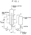
- FIG. 2 A further embodiment of the process according to the present invention is illustrated in Fig. 2 in which the same reference numerals as in Fig. 1 designate similar component parts.
- the apparatus shown in Fig. 2 has a crystallization tower A which is composed of an outer cylindrical housing H and an inner cylindrical member P defining therein an inner passage P1 and coaxially disposed within the outer housing H to define an outer passage H1 therebetween.
- the inner passage P1 is in fluid communication with the outer passage H1 only at an upper portion thereof.
- Designated as Q is a dissolution tank and as 6 is a cooler.
- the crystallization tower A is not communicated with environmental atmosphere but is sealed with an inert gas to prevent the contact with oxygen. In this case, it is not necessary that the crystallization tower A have a highly pressure-resisting structure. When the inside of the tower A is communicated with the outside air, oxygen is apt to be adsorbed in a phenol solution contained in the tower A to cause the coloring of the adduct.
- a raw material feed of a solution of BPA dissolved in phenol is continuously introduced through lines 1 and 2 to a lower part of the outer passage H1 of the crystallization tower A and is directed upward through the outer passage H1.
- the solution is then allow to enter the inner passage P1 from the open topped end of the inside cylindrical member P and is directed downward therethrough.
- the solution is cooled to a predetermined temperature so that BPA is crystallized as an adduct of phenol to form a slurry containing seed crystals of the adduct.
- a portion of the slurry is discharged from the bottom of the inner cylindrical member P, introduced into a cooler 6 through a line 3, a pump 4 and a line 5 and then recycled to the tower A through the line 2.
- Another portion of the slurry is discharged from the tower A, introduced into a dissolution vessel Q through a line 7, a pump 8, lines 9 and 10 and a heater 11, and then recycled to a lower portion of the outer passage H1 of the crystallization tower A through a line 13.
- fine crystals contained in the discharged slurry is dissolved and, hence, the proportion of large crystals of the adduct contained in the slurry within the tower A is increased.
- Fine crystals of the adduct formed in the tower A have a large surface area and are apt to adsorb impurities which account for the coloring of the adduct. By the decrease of the amount of such fine crystals, therefore, it is possible to obtain seed crystals with good hue.
- the content of crystals of the adduct having a particle size of 100 ⁇ m or less is adjusted to not greater than 30 % by weight, more preferably not greater than 20 % by weight, based on the total weight of the adduct crystals recovered from the first crystallization tower A.
- a further portion of the slurry is discharged from the bottom of the tower A through a line 20 for recovery.
- the line 20 is used when the recovered slurry is able to be fed to a next step by gravity.
- the product slurry is recovered through a line 12 by operation of the pump 8.
- the product slurry may also be recovered through a line (not shown) branched from the line 13.
- the product slurry may be fed to a solid-liquid separator (not shown) to obtain high purity grown crystals of the adduct.
- the crystalline adduct is then decomposed to obtain BPA with a high purity and a good hue.
- the product slurry may be introduced as such or after removal of the mother liquor into a crystallization zone to grow the crystals of the adduct.
- the slurry from the lines 2 and 13 is introduced into the tower A in such a manner that an upwardly flowing vortex is established in the outer passage H1.
- This can be achieved by injecting the two flows of the slurry from the lines 2 and 13 into the passage H1 through nozzles (not shown) co-currently in a direction tangential to the inside periphery of the cylindrical outer housing member H.
- the two nozzles connected to the lines 2 and 13 are preferably angularly spaced apart from each other by 90-180 degrees for reasons of establishing smooth vortex flow. However, it is not necessary for the two nozzles to be located in the same horizontal plane.
- the slurry introduced through the lines 2 and 13 into lower parts of the outer passage H1 forms an ascending swirl therein and enters the inner passage P1 through the open topped end of the inside tubular member P.
- the slurry then flows down through the inner passage P1.
- the formation of the vortex in the outer passage H1 gives the following advantages:
- the temperature of the raw material feed supplied through the line 1 is generally higher by 1-20 °C than the saturation temperature of the adduct.
- the crystallization in the tower A is performed at a temperature in the range of 45-70 °C.
- the slurry is cooled in the cooler 6 such that the slurry leaving the cooler 6 has a temperature lower by 10 °C or less, preferably by 5 °C or less, than that of the slurry prior to its passage through the cooler 6.
- the residence time of the phenol solution of BPA in the first crystallization tower A is generally 0.5-10 hours, preferably 0.5-5 hours.
- the slurry is heated in the heater 11 such that the slurry leaving the heater 11 has a temperature higher by 0.5-5 °C than that of the slurry prior to its passage through the heater 11.
- the residence time of the slurry in the dissolution tank Q is generally 3-15 minutes. In the tank Q, crystals of the adduct having particle size of 100 ⁇ m or less are completely dissolved.
- a raw material feed having the composition shown below was subjected to crystallization using the apparatus shown in Fig. 1.
- the slurry recovered through the line 35 was treated for the separation of crystals of BPA/phenol adduct.
- the thus obtained adduct had APHA color of 15 and contained 13 % of fine crystals with a particle diameter of 100 ⁇ m or less.
- the operation conditions of the first and second crystallization towers A and B and in the associated dissolution tanks Q thereof are shown below.
- Second crystallization tower A Second crystallization tower A :
- Example 1 was repeated in the same manner as described except that the second crystallization tower and the associated cooler and dissolution tank were omitted and that the operation temperatures in the crystallization tower A and the tank Q were 47 °C and 48 °C, respectively.
- the slurry recovered through the line 12 was treated for the separation of crystals of BPA/phenol adduct.
- the thus obtained adduct had APHA color of 30 and contained 29 % of fine crystals with a particle diameter of 100 ⁇ m or less.
- a raw material feed having the composition shown below was subjected to crystallization using the apparatus shown in Fig. 2.
- the slurry recovered through the line 20 was treated for the separation of crystals of BPA/phenol adduct.
- the thus obtained adduct contained 20 % of fine crystals with a particle diameter of 100 ⁇ m or less.
- the operation conditions of the crystallization tower A and in the associated dissolution tank Q thereof are shown below.
- a raw material feed having the composition shown below was subjected to crystallization using the apparatus shown in Fig. 2.
- the slurry recovered through the line 20 was treated for the separation of crystals of BPA/phenol adduct.
- the thus obtained adduct contained 29.5 % of fine crystals with a particle diameter of 100 ⁇ m or less.
- the operation conditions of the crystallization tower A and in the associated dissolution tank Q thereof are shown below.
- Example 3 was repeated in the same manner as described except that the dissolution step was omitted. Namely, in this example, the recirculating line including the line 7, pump 8, line 10, heater 11, tank Q and line 13 was closed throughout the process. As a result, the crystals of BPA/phenol adduct recovered from the slurry from the line 20 contained 69 % of fine crystals with a particle diameter of 100 ⁇ m or less.
Landscapes
- Chemical & Material Sciences (AREA)
- Organic Chemistry (AREA)
- Crystallography & Structural Chemistry (AREA)
- Chemical Kinetics & Catalysis (AREA)
- Organic Low-Molecular-Weight Compounds And Preparation Thereof (AREA)
Description
- This invention relates to a process for the production of a crystalline adduct of bisphenol A and phenol and to an apparatus suitable for carrying out the process.
- One well known process for the production of bisphenol A (2,2-bis(4'-hydroxyphenyl)propane) includes reacting acetone with a stoichiometrically excess amount of phenol in the presence of an acid catalyst. With respect to the recovery of bisphenol A from the reaction product, a method is known in which the reaction product is cooled for the crystallization of a bisphenol A/phenol adduct and the resulting adduct is subsequently decomposed into bisphenol A and phenol (U. S. patent No. 3,936,507).
- Since the purity and hue of bisphenol A recovered from a bisphenol A/phenol adduct depend largely upon the purity and hue of the adduct, it is highly desired to produce colorless, high purity crystals of the adduct. To attain this purpose, a method is proposed in which a solution of bisphenol A in phenol is subjected to a series of crystallization stages each of which is followed by separation of crystals and dissolution of the separated crystals. With this method, it is possible to improve the purity of the adduct by increasing the number and/or the size of the crystallization towers. However, since the number and size of the adduct separators and their associated dissolving vessels are also increased with the increase of crystallization towers, the whole apparatus becomes undesirably large, complicated and inefficient.
- The crystallization of the adduct of bisphenol A and phenol is generally performed by feeding a solution of bisphenol A in phenol to a crystallization tower and cooling the solution in the tower to form a slurry of the adduct. The cooling is performed by continuously discharging part of the slurry from the tower, introducing the discharged slurry into a cooler and recycling the cooled slurry to the tower. This cooling method has a problem because it is difficult to control the size of the crystals of the adduct and because fine crystals of the adduct are apt to be produced. Because of their large surface area, the fine crystals of the adduct have a tendency to adsorb impurities.
- The present invention has been made with the foregoing problems of the conventional method in view and provides a process which can efficiently produce a high quality bisphenol A/phenol adduct having a low content of impurities and excellent hue (color characteristics).
- In a paper entitled "Industrial Crystallization for Ultrapure Products" by C.G. Moyers, Jr in CEP, May 1986, pages 42-46, there is disclosed a multistage recrystallization process for the production of a crystalline adduct of bisphenol A and phenol in which each crystallization zone comprises an outer tubular housing and an inner tubular member which defines therein an inner passage and which is coaxially disposed within the outer tubular housing to define a passage therebetween. The inner passage is in fluid communication with the outer passage only at an upper portion of the inner passage. The feed to each crystallization zone enters at a lower portion of the outer passage and the crystal-containing slurry formed in the crystallization zone is discharged from the bottom of the inner passage thereof.
- In accordance with the present invention there is provided a process for the production of a crystalline adduct of bisphenol A and phenol, comprising the steps of:
- providing a crystallization zone having an outer cylindrical housing and an inner cylindrical member defining therein an inner passage and coaxially disposed within said outer cylindrical housing to define an annular, outer passage therebetween, said inner passage being in fluid communication with said outer passage only at an upper portion of said inner passage;
- admixing a solution of bisphenol A dissolved in phenol with cooled slurry to form an admixture;
- feeding said admixture to a lower portion of the outer passage of the first crystallization zone and passing same to said inner passage so that an adduct of bisphenol A and phenol is crystallized to obtain a slurry containing crystals of the adduct;
- discharging the slurry from the bottom of the inner passage of said crystallization zone;
- cooling a first portion of the slurry discharged from said crystallization zone to obtain said cooled slurry;
- heating a second portion of the slurry discharged from said crystallization zone in a dissolution tank to dissolve fine crystals contained therein and recycling said heated slurry direct to said crystallization zone; and
- recovering the crystals from the slurry discharged from said crystallization zone;
- The present invention will now be described in detail below with reference to the accompanying drawings, in which:
- Figs. 1 and 2 are flow diagrams of apparatus suitable for carrying out preferred embodiments of the process according to the present invention.
- In the following descriptions, bisphenol A is referred to as BPA for brevity.
- The apparatus shown in Fig. 1 of the drawings has two, first and second crystallization towers A and B each of which is composed of an outer tubular, preferably cylindrical housing H and an inner tubular, preferably cylindrical member P defining therein an inner passage P1 and coaxially disposed within the outer tubular housing H to define an outer passage H1 therebetween. The inner passage P1 is in fluid communication with the outer passage H1 only at an upper portion thereof. Each of the towers A and B has a dissolution tank Q.
- In each of the crystallization towers A and B, a slurry containing crystals of BPA/phenol adduct dispersed in phenol is contained. Part of the slurry is continuously discharged from the bottom of the inner tubular member P of the tower A (or B) and a portion of the discharged slurry is introduced into a cooler 6 (26) through a line 3 (23), a pump 4 (24) and a line 5 (25). The cooled slurry is then recycled to the tower A (B) through the line 2 (22) for the purpose of effecting the cooling in the crystallization tower A (B).
- Another portion of the slurry discharged from the tower A (or B) is introduced into a dissolution vessel Q through a line 7 (27), a pump 8 (28), lines 9 and 10 (line 29) and a heater 11 (31), and then recycled to a lower portion of the outer passage H1 of the crystallization tower A (B) through a line 13 (33). By this, fine crystals contained in the discharged slurry is dissolved and, hence, the proportion of large crystals of the adduct contained in the slurry within each of the towers A and B is increased. Fine crystals of the adduct have a large surface area and are apt to adsorb impurities which account for the coloring of the adduct. By the decrease of the amount of such fine crystals, therefore, it is possible to obtain seed crystals with good hue. Preferably, the content of crystals of the adduct having a particle size of 100 µm or less is controlled to not greater than 30 % by weight, more preferably not greater than 20 % by weight, based on the total weight of the adduct crystals recovered from the corresponding crystallization tower.
- The slurry from the
lines 2 and 13 (22 and 33) is introduced into the tower A (B) in such a manner that an upwardly flowing vortex is established in the outer passage H1. This can be achieved by injecting the two flows of the slurry from thelines 2 and 13 (22 and 33) into the passage H1 through nozzles (not shown) co-currently in a direction tangential to the inside periphery of the cylindrical outer housing member H. The two nozzles connected to thelines 2 and 13 (22 and 33) are preferably angularly spaced apart from each other by 90-180 degrees. However, it is not necessary for the two nozzles to be located in the same horizontal plane. - Thus, the slurry introduced through the
lines 2 and 13 (22 and 33) into lower parts of the outer passage H1 forms an ascending swirl therein and enters the inner passage P1 through the open topped end of the inside tubular member P. The slurry then flows down through the inner passage P1. The formation of the vortex gives the following advantages: - (1) The flows from the
lines 2 and 13 (22 and 33) are homogeneously mixed effectively; - (2) Deflected flow of the slurry in the outer passage H1 is prevented so that the residence time of respective crystals in the outer passage H1 is uniform, ensuring uniform growth of the crystals; and
- (3) The adduct crystals are prevented from precipitating and accumulating in the outer passage H1.
- A portion of the slurry discharged from the bottom of the inner tubular member P of the first crystallization tower A is admixed with the cooled slurry which has been cooled in the
cooler 26 and which is to be recycled to the second crystallization tower B. By such a direct heat exchange, the slurry from the first crystallization tower A can be effectively and efficiently cooled to permit the effective growth of large crystals. - The temperature of the raw material feed from the line 1 is generally higher by 1-20 °C than the saturation temperature of the adduct. The crystallization in the tower A is performed at a temperature in the range of 45-70 °C. The slurry is cooled in the
cooler 6 such that the slurry leaving thecooler 6 has a temperature lower by 10 °C or less, preferably by 5 °C or less, than that of the slurry prior to its passage through the cooler 6. The residence time of the phenol solution of BPA in the first crystallization tower A is generally 0.5-10 hours, preferably 0.5-5 hours. The slurry is heated in the heater 11 such that the slurry leaving the heater 11 has a temperature higher by 0.5-5 °C than that of the slurry prior to its passage through the heater 11. The residence time of the slurry in the dissolution tank Q is generally 3-15 minutes. In the tank Q, crystals of the adduct having particle size of 100 µm or less are completely dissolved. - A further portion of the slurry discharged from the bottom of the inner tubular member P of the first crystallization tower A is passed through the
line 7, thepump 8 andlines line 22 into a lower portion of the outer passage H1 of the second crystallization tower B. The slurry thus fed to the second crystallization tower B is treated in a manner similar to that of the first crystallization tower A to permit the crystals of the adduct to grow. - The crystallization in the tower B is performed at a temperature lower by generally 3-10 °C than the crystallization temperature in the tank A. The slurry is heated in a
heater 31 such that the slurry leaving theheater 31 has a temperature higher by 0.5-5 °C than that of the slurry prior to its passage through theheater 31 so that the temperature within the tank Q is maintained at a temperature higher by 0.5-5 °C than that of the crystallization tower B. In a dissolution tank Q connected to the second crystallization tower B, crystals of the adduct having particle size of 100 µm or less are completely dissolved. The concentration of the adduct in the slurry discharged from the bottom of the inner tubular member P1 of the second crystallization tower B is generally 35 % by weight or less, preferably 25 % by weight or less. The content of crystals of the adduct having a particle size of 100 µm or less is preferably controlled to not greater than 30 % by weight, more preferably not greater than 20 % by weight, based on the total weight of the adduct crystals. - A further portion of the slurry discharged from the second tower B is recovered as a product through a
line 35. The slurry is then fed to a solid-liquid separator (not shown) to obtain high purity grown crystals of the adduct. The crystalline adduct is then decomposed to obtain BPA with a high purity and a good hue. If desired, the product slurry may be recovered by discharging a part of the heated slurry from the dissolution tank Q. - While the above-described second embodiment is composed of two crystallization zones A and B, it is possible to increase the number of the crystallization zones. Thus, the process of this invention may generally use two or more, first to n-th crystallization zones connected in series. The raw material feed is introduced into the first crystallization zone and the product slurry is recovered from the slurry in the downstream end, n-th crystallization zone. A portion of the slurry discharged from each of the first to (n-1)th crystallization zones is fed to the next crystallization zone located immediately downstream thereof. Another portion of the slurry is discharged from each of said first to n-th crystallization zones, introduced into its associated cooler and recycled back to the corresponding crystallization zone so that the slurry in each of the first to n-th crystallization zones is cooled such that the temperature of the slurry in one crystallization zone is lower by generally 3-10 °C, preferably 5-8 °C, than that in the adjacent crystallization zone located upstream of the said one crystallization zone. The dissolution of fine crystals using the dissolution tank Q should be performed at least in the n-th crystallization tower. Namely, in part or all of the first to (n-1)th crystallization towers, such a dissolution step may be omitted.
- A further embodiment of the process according to the present invention is illustrated in Fig. 2 in which the same reference numerals as in Fig. 1 designate similar component parts.
- The apparatus shown in Fig. 2 has a crystallization tower A which is composed of an outer cylindrical housing H and an inner cylindrical member P defining therein an inner passage P1 and coaxially disposed within the outer housing H to define an outer passage H1 therebetween. The inner passage P1 is in fluid communication with the outer passage H1 only at an upper portion thereof. Designated as Q is a dissolution tank and as 6 is a cooler.
- The crystallization tower A is not communicated with environmental atmosphere but is sealed with an inert gas to prevent the contact with oxygen. In this case, it is not necessary that the crystallization tower A have a highly pressure-resisting structure. When the inside of the tower A is communicated with the outside air, oxygen is apt to be adsorbed in a phenol solution contained in the tower A to cause the coloring of the adduct.
- A raw material feed of a solution of BPA dissolved in phenol is continuously introduced through
lines 1 and 2 to a lower part of the outer passage H1 of the crystallization tower A and is directed upward through the outer passage H1. The solution is then allow to enter the inner passage P1 from the open topped end of the inside cylindrical member P and is directed downward therethrough. During the passage of the feed solution through the outer and inner passages H1 and P1 of the tower A, the solution is cooled to a predetermined temperature so that BPA is crystallized as an adduct of phenol to form a slurry containing seed crystals of the adduct. - For the purpose of effecting the cooling in the crystallization tower A, a portion of the slurry is discharged from the bottom of the inner cylindrical member P, introduced into a
cooler 6 through aline 3, apump 4 and aline 5 and then recycled to the tower A through theline 2. - Another portion of the slurry is discharged from the tower A, introduced into a dissolution vessel Q through a
line 7, apump 8,lines 9 and 10 and a heater 11, and then recycled to a lower portion of the outer passage H1 of the crystallization tower A through aline 13. By this, fine crystals contained in the discharged slurry is dissolved and, hence, the proportion of large crystals of the adduct contained in the slurry within the tower A is increased. Fine crystals of the adduct formed in the tower A have a large surface area and are apt to adsorb impurities which account for the coloring of the adduct. By the decrease of the amount of such fine crystals, therefore, it is possible to obtain seed crystals with good hue. Preferably, the content of crystals of the adduct having a particle size of 100 µm or less is adjusted to not greater than 30 % by weight, more preferably not greater than 20 % by weight, based on the total weight of the adduct crystals recovered from the first crystallization tower A. - A further portion of the slurry is discharged from the bottom of the tower A through a
line 20 for recovery. Theline 20 is used when the recovered slurry is able to be fed to a next step by gravity. When such a gravity flow is not feasible, the product slurry is recovered through aline 12 by operation of thepump 8. Alternatively, the product slurry may also be recovered through a line (not shown) branched from theline 13. The product slurry may be fed to a solid-liquid separator (not shown) to obtain high purity grown crystals of the adduct. The crystalline adduct is then decomposed to obtain BPA with a high purity and a good hue. Alternatively, the product slurry may be introduced as such or after removal of the mother liquor into a crystallization zone to grow the crystals of the adduct. - In this embodiment, the slurry from the
lines lines lines - Thus, the slurry introduced through the
lines - (1) The flows from the
lines - (2) Deflected flow of the slurry in the outer passage H1 is prevented so that the residence time of respective crystals in the outer passage H1 is uniform, ensuring uniform growth of the crystals; and
- (3) The adduct crystals are prevented from precipitating and accumulating in the outer passage H1.
- The temperature of the raw material feed supplied through the line 1 is generally higher by 1-20 °C than the saturation temperature of the adduct. The crystallization in the tower A is performed at a temperature in the range of 45-70 °C. The slurry is cooled in the cooler 6 such that the slurry leaving the
cooler 6 has a temperature lower by 10 °C or less, preferably by 5 °C or less, than that of the slurry prior to its passage through thecooler 6. The residence time of the phenol solution of BPA in the first crystallization tower A is generally 0.5-10 hours, preferably 0.5-5 hours. The slurry is heated in the heater 11 such that the slurry leaving the heater 11 has a temperature higher by 0.5-5 °C than that of the slurry prior to its passage through the heater 11. The residence time of the slurry in the dissolution tank Q is generally 3-15 minutes. In the tank Q, crystals of the adduct having particle size of 100 µm or less are completely dissolved. - The following examples will further illustrate the present invention. "Percentages" are by weight. The APHA number referred to in the examples is measured in accordance with the method specified in ASTM D 1686, "Standard Test Method for Color of Solid Aromatic Hydrocarbons and Related Materials in the Molten State".
- A raw material feed having the composition shown below was subjected to crystallization using the apparatus shown in Fig. 1. The slurry recovered through the
line 35 was treated for the separation of crystals of BPA/phenol adduct. The thus obtained adduct had APHA color of 15 and contained 13 % of fine crystals with a particle diameter of 100 µm or less. The operation conditions of the first and second crystallization towers A and B and in the associated dissolution tanks Q thereof are shown below. - BPA: 22 %
Phenol: 74 %
Others: 4 % - Temperature: 54 °C
Residence time: 120 minutes - Temperature: 55 °C
Residence time: 6 minutes - Temperature: 47 °C
Residence time: 120 minutes - Temperature: 48 °C
Residence time: 6 minutes - Example 1 was repeated in the same manner as described except that the second crystallization tower and the associated cooler and dissolution tank were omitted and that the operation temperatures in the crystallization tower A and the tank Q were 47 °C and 48 °C, respectively. The slurry recovered through the
line 12 was treated for the separation of crystals of BPA/phenol adduct. The thus obtained adduct had APHA color of 30 and contained 29 % of fine crystals with a particle diameter of 100 µm or less. - A raw material feed having the composition shown below was subjected to crystallization using the apparatus shown in Fig. 2. The slurry recovered through the
line 20 was treated for the separation of crystals of BPA/phenol adduct. The thus obtained adduct contained 20 % of fine crystals with a particle diameter of 100 µm or less. The operation conditions of the crystallization tower A and in the associated dissolution tank Q thereof are shown below. - BPA: 22 %
Phenol: 74 %
Others: 4 % - Temperature: 54 °C
Residence time: 120 minutes - Temperature: 55 °C
Residence time: 6 minutes - A raw material feed having the composition shown below was subjected to crystallization using the apparatus shown in Fig. 2. The slurry recovered through the
line 20 was treated for the separation of crystals of BPA/phenol adduct. The thus obtained adduct contained 29.5 % of fine crystals with a particle diameter of 100 µm or less. The operation conditions of the crystallization tower A and in the associated dissolution tank Q thereof are shown below. - BPA: 22 %
Phenol: 74 %
Others: 4 % - Temperature: 44 °C
Residence time: 120 minutes - Temperature: 49 °C
Residence time: 4 minutes - Example 3 was repeated in the same manner as described except that the dissolution step was omitted. Namely, in this example, the recirculating line including the
line 7, pump 8,line 10, heater 11, tank Q andline 13 was closed throughout the process. As a result, the crystals of BPA/phenol adduct recovered from the slurry from theline 20 contained 69 % of fine crystals with a particle diameter of 100 µm or less.
Claims (4)
- A process for the production of a crystalline adduct of bisphenol A and phenol, comprising the steps of:providing a crystallization zone having an outer cylindrical housing and an inner cylindrical member defining therein an inner passage and coaxially disposed within said outer cylindrical housing to define an annular, outer passage therebetween, said inner passage being in fluid communication with said outer passage only at an upper portion of said inner passage;admixing a solution of bisphenol A dissolved in phenol with cooled slurry to form an admixture;feeding said admixture to a lower portion of the outer passage of the first crystallization zone and passing same to said inner passage so that an adduct of bisphenol A and phenol is crystallized to obtain a slurry containing crystals of the adduct;discharging the slurry from the bottom of the inner passage of said crystallization zone;cooling a first portion of the slurry discharged from said crystallization zone to obtain said cooled slurry;heating a second portion of the slurry discharged from said crystallization zone in a dissolution tank to dissolve fine crystals contained therein and recycling said heated slurry direct to said crystallization zone; andrecovering the crystals from the slurry discharged from said crystallization zone;each of said admixture and said heated slurry being fed to said outer passage of said crystallization zone such that the slurry in said outer passage forms a vortex flow.
- A process for the production of a crystalline adduct of bisphenol A and phenol according to Claim 1, comprising the steps of:providing two or more, first to n-th crystallization zones connected in series and each having an outer tubular housing and an inner tubular member defining therein an inner passage and coaxially disposed within said outer tubular housing to define an outer passage therebetween, said inner passage being in fluid communication with said outer passage only at an upper portion of said inner passage;crystallizing an adduct of bisphenol A and phenol in each of said first to n-th crystallization zones to form a slurry;discharging the slurry from the bottom of the inner passage of each of said first to n-th crystallization zones;cooling a portion of the slurry discharged from each of said two or more crystallization zones and recycling the cooled slurry to the corresponding crystallization zone so that the slurry in each of said first to n-th crystallization zones is cooled such that the temperature of the slurry in one crystallization zone is lower than that in the adjacent crystallization zone located upstream of said one crystallization zone;heating another portion of the slurry discharged from said n-th crystallization zone in a dissolution zone to dissolve fine crystals contained therein, and recycling said heated slurry direct to said n-th crystallization zone;admixing a solution of bisphenol A dissolved in phenol with said cooled slurry to be recycled to said first crystallization zone, feeding the resulting admixture to a lower portion of the outer passage of the first crystallization zone and passing same to the inner passage to effect the crystallization of the adduct of bisphenol A and phenol;mixing part of the slurry discharged from each of said first to (n-1)th crystallization zones with the cooled slurry to be recycled to that crystallization zone located immediately downstream thereof, feeding the resulting mixture to a lower portion of the outer passage of that crystallization zone and passing same to the inner passage of that crystallization zone to effect the crystallization of the adduct of bisphenol A and phenol; andrecovering a further portion of the slurry discharged from said n-th crystallization zone;each of said heated slurry, said admixture and said mixture being fed to the outer passage of the corresponding crystallization zone such that the slurry in said outer passage forms a vortex flow.
- A process as claimed in Claim 2, further comprising heating another portion of the slurry discharged from each of said first to (n-1)th crystallization zones in a dissolution zone to dissolve fine crystals contained therein and recycling said heated slurry direct to the corresponding crystallization zone to facilitate the formation of said vortex flow.
- A process as claimed in any preceding claim, wherein said recovered slurry is filtered to separate the crystals such that the separated crystals contain less than 20% by weight of crystals with a particle diameter of 100 µm or less.
Priority Applications (2)
| Application Number | Priority Date | Filing Date | Title |
|---|---|---|---|
| EP96200435A EP0718267B1 (en) | 1991-07-10 | 1992-05-29 | Process for the production of crystalline adduct of bisphenol A and phenol and apparatus therefor |
| EP96200436A EP0718268B1 (en) | 1991-07-10 | 1992-05-29 | Process for the production of crystalline adduct of bisphenol A and phenol |
Applications Claiming Priority (12)
| Application Number | Priority Date | Filing Date | Title |
|---|---|---|---|
| JP169557/91 | 1991-07-10 | ||
| JP16955791A JP3238426B2 (en) | 1991-07-10 | 1991-07-10 | Continuous crystallization method and apparatus |
| JP292211/91 | 1991-10-11 | ||
| JP3292211A JPH0597743A (en) | 1991-10-11 | 1991-10-11 | Production of high-grade bisphenol a-phenol adduct |
| JP30652191A JP3171465B2 (en) | 1991-10-25 | 1991-10-25 | Method for producing bisphenol A / phenol crystal adduct having good hue |
| JP306520/91 | 1991-10-25 | ||
| JP306521/91 | 1991-10-25 | ||
| JP30652491A JP2796556B2 (en) | 1991-10-25 | 1991-10-25 | Method for producing high-grade bisphenol A / phenol crystal adduct |
| JP306524/91 | 1991-10-25 | ||
| JP30652091A JP3171464B2 (en) | 1991-10-25 | 1991-10-25 | Method for producing bisphenol A / phenol crystal adduct slurry |
| JP311989/91 | 1991-10-30 | ||
| JP3311989A JP2683762B2 (en) | 1991-10-30 | 1991-10-30 | Method for producing bisphenol A / phenol crystal adduct having good hue |
Related Child Applications (4)
| Application Number | Title | Priority Date | Filing Date |
|---|---|---|---|
| EP96200435A Division EP0718267B1 (en) | 1991-07-10 | 1992-05-29 | Process for the production of crystalline adduct of bisphenol A and phenol and apparatus therefor |
| EP96200435.4 Division-Into | 1992-05-29 | ||
| EP96200436A Division EP0718268B1 (en) | 1991-07-10 | 1992-05-29 | Process for the production of crystalline adduct of bisphenol A and phenol |
| EP96200436.2 Division-Into | 1992-05-29 |
Publications (3)
| Publication Number | Publication Date |
|---|---|
| EP0522700A2 EP0522700A2 (en) | 1993-01-13 |
| EP0522700A3 EP0522700A3 (en) | 1993-11-03 |
| EP0522700B1 true EP0522700B1 (en) | 1997-01-29 |
Family
ID=27553361
Family Applications (3)
| Application Number | Title | Priority Date | Filing Date |
|---|---|---|---|
| EP96200436A Expired - Lifetime EP0718268B1 (en) | 1991-07-10 | 1992-05-29 | Process for the production of crystalline adduct of bisphenol A and phenol |
| EP92304932A Expired - Lifetime EP0522700B1 (en) | 1991-07-10 | 1992-05-29 | Process for the production of crystalline adduct of bisphenol A and phenol and apparatus therefor |
| EP96200435A Expired - Lifetime EP0718267B1 (en) | 1991-07-10 | 1992-05-29 | Process for the production of crystalline adduct of bisphenol A and phenol and apparatus therefor |
Family Applications Before (1)
| Application Number | Title | Priority Date | Filing Date |
|---|---|---|---|
| EP96200436A Expired - Lifetime EP0718268B1 (en) | 1991-07-10 | 1992-05-29 | Process for the production of crystalline adduct of bisphenol A and phenol |
Family Applications After (1)
| Application Number | Title | Priority Date | Filing Date |
|---|---|---|---|
| EP96200435A Expired - Lifetime EP0718267B1 (en) | 1991-07-10 | 1992-05-29 | Process for the production of crystalline adduct of bisphenol A and phenol and apparatus therefor |
Country Status (4)
| Country | Link |
|---|---|
| US (1) | US5345000A (en) |
| EP (3) | EP0718268B1 (en) |
| DE (3) | DE69227850T2 (en) |
| ES (3) | ES2097877T3 (en) |
Families Citing this family (27)
| Publication number | Priority date | Publication date | Assignee | Title |
|---|---|---|---|---|
| US5434316A (en) * | 1994-07-28 | 1995-07-18 | General Electric Company | Purification of bisphenol-A |
| US5874644A (en) * | 1996-04-12 | 1999-02-23 | Gammill; Ben | Method and system for bisphenol a production using controlled turbulence |
| US5959158A (en) * | 1996-04-12 | 1999-09-28 | Gammill; Ben | Method and system for bisphenol a production using water |
| WO2000047542A1 (en) * | 1999-02-12 | 2000-08-17 | General Electric Company | A process for removing adhered crystals in a bpa/phenol crystallizer system |
| CN1079092C (en) * | 1999-07-12 | 2002-02-13 | 和龙市化工厂 | Process for preparing polycarbonate-class biphenol A by heteropoly acid method |
| DE19954786A1 (en) | 1999-11-15 | 2001-05-17 | Bayer Ag | Melt crystallization |
| DE10015014A1 (en) | 2000-03-27 | 2001-10-04 | Bayer Ag | Process for the preparation of bisphenols |
| US6203612B1 (en) * | 2000-03-30 | 2001-03-20 | General Electric Company | Process for cleaning bisphenol crystallizer |
| JP2004513932A (en) * | 2000-11-16 | 2004-05-13 | ストーン アンド ウエブスター,インク. | Economic purification of bisphenol A |
| US6703530B2 (en) | 2002-02-28 | 2004-03-09 | General Electric Company | Chemical reactor system and process |
| US20050075520A1 (en) * | 2002-03-13 | 2005-04-07 | O'young Drow Lionel | System and method of producing bisphenol-A (BPA) using two stage crystallization |
| US6960697B2 (en) * | 2002-03-13 | 2005-11-01 | Mitsubishi Chemical Corporation | System and method of producing bisphenol-A (BPA) |
| DE10218107A1 (en) | 2002-04-23 | 2003-11-20 | Jenapharm Gmbh | Process for the production of crystals of steroids, crystals available thereafter and their use in pharmaceutical formulations |
| WO2004020377A1 (en) * | 2002-08-28 | 2004-03-11 | Idemitsu Kosan Co., Ltd. | Process for producing bisphenol a |
| JP4419492B2 (en) | 2002-10-28 | 2010-02-24 | 三菱化学株式会社 | Improved continuous crystallization method |
| CN100402478C (en) | 2003-03-27 | 2008-07-16 | 三井化学株式会社 | The production method of bisphenol A |
| DE102004024688A1 (en) * | 2004-05-19 | 2005-12-15 | Basf Ag | partition column |
| DE102005025788A1 (en) | 2005-06-04 | 2006-12-07 | Bayer Materialscience Ag | Process for the preparation of high purity bisphenol A |
| EP1940760B1 (en) * | 2005-10-07 | 2016-08-24 | Badger Licensing LLC | Bisphenol-a plant yield enhancement |
| EP2142491B2 (en) * | 2007-05-09 | 2016-06-22 | Badger Licensing LLC | Bpa process improvement |
| DE102007021935A1 (en) * | 2007-05-10 | 2008-11-20 | Bayer Materialscience Ag | Process and preparation of bisphenol A with extended lifetime in crystallization |
| DE102010003711B4 (en) | 2010-04-08 | 2015-04-09 | Jesalis Pharma Gmbh | Process for the preparation of crystalline active substance particles |
| CN102657951B (en) * | 2012-04-28 | 2014-12-03 | 中粮生物化学(安徽)股份有限公司 | Method for extracting crystal from magma |
| CN105233522B (en) * | 2015-10-29 | 2017-06-27 | 中石化南京工程有限公司 | A kind of freezing and crystallizing device |
| KR101932818B1 (en) * | 2015-11-19 | 2019-03-20 | 주식회사 엘지화학 | Apparatus and method for preparing bisphenol a |
| CN109415284B (en) | 2016-07-12 | 2022-06-17 | 沙特基础工业全球技术有限公司 | Preparation of bisphenol A |
| EP3487833B1 (en) | 2016-07-22 | 2020-08-26 | SABIC Global Technologies B.V. | Manufacture of bisphenol a |
Family Cites Families (6)
| Publication number | Priority date | Publication date | Assignee | Title |
|---|---|---|---|---|
| CA687780A (en) * | 1964-06-02 | Union Carbide Corporation | Crystallization of bisphenol adduct | |
| US4209646A (en) * | 1974-10-31 | 1980-06-24 | Rhone-Poulenc Industries | Process for crystallizing an adduct of 2,2-di(4-hydroxyphenyl) propane and phenol |
| FR2289476A1 (en) * | 1974-10-31 | 1976-05-28 | Rhone Poulenc Ind | PROCESS FOR CRYSTALLIZING A DI (4-HYDROXY-PHENYL) 2,2 PROPANE AND PHENOL COMPLEX |
| JPH029832A (en) * | 1988-02-19 | 1990-01-12 | Mitsui Toatsu Chem Inc | Washing and recovery of solid |
| US4950806A (en) * | 1988-02-22 | 1990-08-21 | Mitsui Toatsu Chemicals, Inc. | Process for crystallizing adduct of bisphenol A with phenol |
| US4954661A (en) * | 1988-03-11 | 1990-09-04 | Mitsui Toatsu Chemicals, Inc. | Process for preparing high-purity bisphenol A |
-
1992
- 1992-05-29 DE DE69227850T patent/DE69227850T2/en not_active Expired - Lifetime
- 1992-05-29 DE DE69217133T patent/DE69217133T2/en not_active Expired - Lifetime
- 1992-05-29 ES ES92304932T patent/ES2097877T3/en not_active Expired - Lifetime
- 1992-05-29 ES ES96200436T patent/ES2126977T3/en not_active Expired - Lifetime
- 1992-05-29 ES ES96200435T patent/ES2126976T3/en not_active Expired - Lifetime
- 1992-05-29 DE DE69227849T patent/DE69227849T2/en not_active Expired - Lifetime
- 1992-05-29 EP EP96200436A patent/EP0718268B1/en not_active Expired - Lifetime
- 1992-05-29 EP EP92304932A patent/EP0522700B1/en not_active Expired - Lifetime
- 1992-05-29 EP EP96200435A patent/EP0718267B1/en not_active Expired - Lifetime
-
1993
- 1993-03-03 US US08/026,126 patent/US5345000A/en not_active Expired - Lifetime
Non-Patent Citations (1)
| Title |
|---|
| CEP, May 1986, Moyers et al. * |
Also Published As
| Publication number | Publication date |
|---|---|
| EP0718267A3 (en) | 1996-08-21 |
| EP0718268B1 (en) | 1998-12-09 |
| EP0718267B1 (en) | 1998-12-09 |
| US5345000A (en) | 1994-09-06 |
| ES2097877T3 (en) | 1997-04-16 |
| DE69227849T2 (en) | 1999-04-29 |
| EP0718268A3 (en) | 1996-08-21 |
| DE69227850T2 (en) | 1999-04-29 |
| DE69227850D1 (en) | 1999-01-21 |
| EP0718268A2 (en) | 1996-06-26 |
| ES2126977T3 (en) | 1999-04-01 |
| ES2126976T3 (en) | 1999-04-01 |
| EP0522700A2 (en) | 1993-01-13 |
| DE69217133T2 (en) | 1997-07-17 |
| DE69227849D1 (en) | 1999-01-21 |
| EP0522700A3 (en) | 1993-11-03 |
| EP0718267A2 (en) | 1996-06-26 |
| DE69217133D1 (en) | 1997-03-13 |
Similar Documents
| Publication | Publication Date | Title |
|---|---|---|
| US5345000A (en) | Process for the production of crystalline adduct of bisphenol A and phenol and apparatus therefor | |
| EP0683761B1 (en) | A novel process for the production of high purity and ultrapure bisphenol-a | |
| EP0105524B1 (en) | Countercurrent, cooling crystallization and purification method for multi-component molten mixture | |
| CN109453539B (en) | Device for evaporative crystallization and method for crystallizing sucralose | |
| US6689464B1 (en) | Method and device for producing bisphenol a prills and bisphenol a prills produced according to this method | |
| US5545764A (en) | Process for the continuous production of high purity bisphenol A | |
| US5368827A (en) | Process for the production of crystalline adduct of bisphenol A and phenol and apparatus therefor | |
| CA2005470C (en) | Process for continuous purification of bisphenols | |
| JP2001316313A (en) | Method for producing crystal adduct of bisphenol A and phenol for producing high-grade bisphenol A | |
| EP1678114B1 (en) | Crystallization of adipic acid from its solution in aqueous nitric acid | |
| US4530823A (en) | Uranium peroxide in the form of spherical particles having good flowability and processes for preparing same | |
| CN111099954B (en) | Method for producing p-xylene | |
| US3649686A (en) | Continuous process for the preparation of acylsulfanilyl chloride | |
| FI78927B (en) | FOERFARANDE OCH ANORDNING FOER PRODUCERING AV KRISTALLISERAD MONOHYDRATISK DEXTROS. | |
| KR100260497B1 (en) | Process for preparing prilled bisphenol a | |
| JP4254221B2 (en) | Crystallization method of bisphenol A / phenol adduct | |
| US5688742A (en) | Water based formation of a beaded product | |
| KR100262810B1 (en) | Preparation method of purified terephthalic acid | |
| CN119874472B (en) | A multi-stage washing process and system for producing high-concentration para-xylene | |
| EP4692039A1 (en) | Method for preparation of acrylic acid | |
| JPH06107582A (en) | Method for producing bisphenol A | |
| JPH05117190A (en) | Production of bisphenol a-phenol crystalline adduct slurry | |
| JP2683762B2 (en) | Method for producing bisphenol A / phenol crystal adduct having good hue | |
| JP2623344B2 (en) | Method for separation and purification of β-monoisopropylnaphthalene | |
| EP0115754B1 (en) | Two-stage crystallization of nitrilotriacetonitrile from a hot solution |
Legal Events
| Date | Code | Title | Description |
|---|---|---|---|
| PUAI | Public reference made under article 153(3) epc to a published international application that has entered the european phase |
Free format text: ORIGINAL CODE: 0009012 |
|
| AK | Designated contracting states |
Kind code of ref document: A2 Designated state(s): DE ES FR GB IT NL |
|
| PUAL | Search report despatched |
Free format text: ORIGINAL CODE: 0009013 |
|
| AK | Designated contracting states |
Kind code of ref document: A3 Designated state(s): DE ES FR GB IT NL |
|
| 17P | Request for examination filed |
Effective date: 19940427 |
|
| 17Q | First examination report despatched |
Effective date: 19950804 |
|
| GRAG | Despatch of communication of intention to grant |
Free format text: ORIGINAL CODE: EPIDOS AGRA |
|
| GRAH | Despatch of communication of intention to grant a patent |
Free format text: ORIGINAL CODE: EPIDOS IGRA |
|
| GRAH | Despatch of communication of intention to grant a patent |
Free format text: ORIGINAL CODE: EPIDOS IGRA |
|
| GRAA | (expected) grant |
Free format text: ORIGINAL CODE: 0009210 |
|
| AK | Designated contracting states |
Kind code of ref document: B1 Designated state(s): DE ES FR GB IT NL |
|
| DX | Miscellaneous (deleted) | ||
| REF | Corresponds to: |
Ref document number: 69217133 Country of ref document: DE Date of ref document: 19970313 |
|
| REG | Reference to a national code |
Ref country code: ES Ref legal event code: FG2A Ref document number: 2097877 Country of ref document: ES Kind code of ref document: T3 |
|
| ITF | It: translation for a ep patent filed | ||
| ET | Fr: translation filed | ||
| PLBE | No opposition filed within time limit |
Free format text: ORIGINAL CODE: 0009261 |
|
| STAA | Information on the status of an ep patent application or granted ep patent |
Free format text: STATUS: NO OPPOSITION FILED WITHIN TIME LIMIT |
|
| 26N | No opposition filed | ||
| REG | Reference to a national code |
Ref country code: GB Ref legal event code: IF02 |
|
| REG | Reference to a national code |
Ref country code: GB Ref legal event code: 732E |
|
| NLS | Nl: assignments of ep-patents |
Owner name: MITSUBISHI CHEMICAL CORPORATION |
|
| REG | Reference to a national code |
Ref country code: ES Ref legal event code: PC2A |
|
| REG | Reference to a national code |
Ref country code: FR Ref legal event code: TP |
|
| PGFP | Annual fee paid to national office [announced via postgrant information from national office to epo] |
Ref country code: FR Payment date: 20040510 Year of fee payment: 13 |
|
| PGFP | Annual fee paid to national office [announced via postgrant information from national office to epo] |
Ref country code: GB Payment date: 20040526 Year of fee payment: 13 |
|
| PG25 | Lapsed in a contracting state [announced via postgrant information from national office to epo] |
Ref country code: IT Free format text: LAPSE BECAUSE OF NON-PAYMENT OF DUE FEES;WARNING: LAPSES OF ITALIAN PATENTS WITH EFFECTIVE DATE BEFORE 2007 MAY HAVE OCCURRED AT ANY TIME BEFORE 2007. THE CORRECT EFFECTIVE DATE MAY BE DIFFERENT FROM THE ONE RECORDED. Effective date: 20050529 Ref country code: GB Free format text: LAPSE BECAUSE OF NON-PAYMENT OF DUE FEES Effective date: 20050529 |
|
| GBPC | Gb: european patent ceased through non-payment of renewal fee |
Effective date: 20050529 |
|
| PG25 | Lapsed in a contracting state [announced via postgrant information from national office to epo] |
Ref country code: FR Free format text: LAPSE BECAUSE OF NON-PAYMENT OF DUE FEES Effective date: 20060131 |
|
| REG | Reference to a national code |
Ref country code: FR Ref legal event code: ST Effective date: 20060131 |
|
| PGFP | Annual fee paid to national office [announced via postgrant information from national office to epo] |
Ref country code: ES Payment date: 20110520 Year of fee payment: 20 |
|
| PGFP | Annual fee paid to national office [announced via postgrant information from national office to epo] |
Ref country code: NL Payment date: 20110520 Year of fee payment: 20 |
|
| PGFP | Annual fee paid to national office [announced via postgrant information from national office to epo] |
Ref country code: DE Payment date: 20110525 Year of fee payment: 20 |
|
| REG | Reference to a national code |
Ref country code: DE Ref legal event code: R071 Ref document number: 69217133 Country of ref document: DE |
|
| REG | Reference to a national code |
Ref country code: NL Ref legal event code: V4 Effective date: 20120529 Ref country code: DE Ref legal event code: R071 Ref document number: 69217133 Country of ref document: DE |
|
| PG25 | Lapsed in a contracting state [announced via postgrant information from national office to epo] |
Ref country code: DE Free format text: LAPSE BECAUSE OF EXPIRATION OF PROTECTION Effective date: 20120530 |
|
| REG | Reference to a national code |
Ref country code: ES Ref legal event code: FD2A Effective date: 20140827 |
|
| PG25 | Lapsed in a contracting state [announced via postgrant information from national office to epo] |
Ref country code: ES Free format text: LAPSE BECAUSE OF EXPIRATION OF PROTECTION Effective date: 20120530 |