EP0521654A2 - Disc for recording information signals - Google Patents
Disc for recording information signals Download PDFInfo
- Publication number
- EP0521654A2 EP0521654A2 EP92305850A EP92305850A EP0521654A2 EP 0521654 A2 EP0521654 A2 EP 0521654A2 EP 92305850 A EP92305850 A EP 92305850A EP 92305850 A EP92305850 A EP 92305850A EP 0521654 A2 EP0521654 A2 EP 0521654A2
- Authority
- EP
- European Patent Office
- Prior art keywords
- recess
- disc substrate
- disc
- major surface
- magnetic member
- Prior art date
- Legal status (The legal status is an assumption and is not a legal conclusion. Google has not performed a legal analysis and makes no representation as to the accuracy of the status listed.)
- Granted
Links
- 239000000758 substrate Substances 0.000 claims abstract description 187
- 238000000034 method Methods 0.000 claims description 22
- 230000003287 optical effect Effects 0.000 claims description 20
- 230000001747 exhibiting effect Effects 0.000 claims description 4
- 229920003002 synthetic resin Polymers 0.000 abstract description 8
- 239000000057 synthetic resin Substances 0.000 abstract description 8
- 239000002184 metal Substances 0.000 description 79
- 239000000853 adhesive Substances 0.000 description 6
- 230000001070 adhesive effect Effects 0.000 description 6
- 238000010438 heat treatment Methods 0.000 description 6
- 230000010355 oscillation Effects 0.000 description 6
- 229920005668 polycarbonate resin Polymers 0.000 description 6
- 239000004431 polycarbonate resin Substances 0.000 description 6
- 230000002093 peripheral effect Effects 0.000 description 5
- 230000001681 protective effect Effects 0.000 description 4
- 230000000717 retained effect Effects 0.000 description 4
- 238000000465 moulding Methods 0.000 description 3
- 238000000151 deposition Methods 0.000 description 2
- 238000003780 insertion Methods 0.000 description 2
- 230000037431 insertion Effects 0.000 description 2
- 230000000644 propagated effect Effects 0.000 description 2
- 238000004080 punching Methods 0.000 description 2
- 229910001220 stainless steel Inorganic materials 0.000 description 2
- 239000010935 stainless steel Substances 0.000 description 2
- 239000002390 adhesive tape Substances 0.000 description 1
- 230000015572 biosynthetic process Effects 0.000 description 1
- 230000007547 defect Effects 0.000 description 1
- 230000008021 deposition Effects 0.000 description 1
- 238000004519 manufacturing process Methods 0.000 description 1
- 239000000463 material Substances 0.000 description 1
- 238000002360 preparation method Methods 0.000 description 1
- 230000000284 resting effect Effects 0.000 description 1
- 229920002379 silicone rubber Polymers 0.000 description 1
- 125000006850 spacer group Chemical group 0.000 description 1
- 238000004544 sputter deposition Methods 0.000 description 1
- 229920002994 synthetic fiber Polymers 0.000 description 1
- 238000003466 welding Methods 0.000 description 1
Images


Classifications
-
- G—PHYSICS
- G11—INFORMATION STORAGE
- G11B—INFORMATION STORAGE BASED ON RELATIVE MOVEMENT BETWEEN RECORD CARRIER AND TRANSDUCER
- G11B7/00—Recording or reproducing by optical means, e.g. recording using a thermal beam of optical radiation by modifying optical properties or the physical structure, reproducing using an optical beam at lower power by sensing optical properties; Record carriers therefor
-
- G—PHYSICS
- G11—INFORMATION STORAGE
- G11B—INFORMATION STORAGE BASED ON RELATIVE MOVEMENT BETWEEN RECORD CARRIER AND TRANSDUCER
- G11B23/00—Record carriers not specific to the method of recording or reproducing; Accessories, e.g. containers, specially adapted for co-operation with the recording or reproducing apparatus ; Intermediate mediums; Apparatus or processes specially adapted for their manufacture
- G11B23/0014—Record carriers not specific to the method of recording or reproducing; Accessories, e.g. containers, specially adapted for co-operation with the recording or reproducing apparatus ; Intermediate mediums; Apparatus or processes specially adapted for their manufacture record carriers not specifically of filamentary or web form
- G11B23/0021—Record carriers not specific to the method of recording or reproducing; Accessories, e.g. containers, specially adapted for co-operation with the recording or reproducing apparatus ; Intermediate mediums; Apparatus or processes specially adapted for their manufacture record carriers not specifically of filamentary or web form discs
- G11B23/0028—Details
- G11B23/0035—Details means incorporated in the disc, e.g. hub, to enable its guiding, loading or driving
Definitions
- the invention relates to a disc for recording information signals, such as an optical disc or a magneto-optical disc.
- Discs have hitherto been proposed to record information signals such as a write-once type optical disc or a magneto-optical disc.
- Such discs may be of extremely small diameter and can permit high density recording of information signals.
- a magneto-optical disc may have a diameter as small as 64 mm or even less.
- Such a magneto-optical disc which is of a small diameter and permits of high density recording can be loaded into a disc rotating and driving device and rotationally driven at a higher velocity. Whilst the disc is rotationally driven at high velocity, a light beam can be radiated, for an optical disc, onto fine recording tracks provided in a signal recording layer on a surface of the magneto-optical disc or an external magnetic field can be impressed by a magnetic head onto the other surface of the magneto-optical disc to record desired information signals.
- the magneto-optical disc For radiating the light beam on the fine recording tracks, the magneto-optical disc, rotationally driven at an elevated velocity, needs to be retained integrally with a disc table of a disc rotating and driving device as well as being loaded with its centre of rotation aligned very accurately with the axis of the disc table.
- a disc loading system for accurately positioning and loading a magneto-optical disc on a disc table, a disc loading system is proposed in, for example, Patent Specifications US-A-4 926 410, US-A-4 829 510 and US-A-4 787 009, in which a magnetic plate, such as a magnetic metal plate, provided on the magneto-optical disc, is attracted by a magnet provided on the disc table to chuck the magneto-optical disc on the disc table.
- a magnetic plate such as a magnetic metal plate
- a magneto-optical disc 100 employed in a disc chucking system which uses the force of attraction of a magnet, includes a disc substrate 101 moulded from a transparent synthetic material, such as polycarbonate resin, into the shape of a disc.
- a recording layer for information signals is deposited by vapour deposition or sputtering on one major surface 101 a of the disc substrate 101.
- the other major surface 101 b of the disc substrate 101, opposite to said one major surface 101 a on which the recording layer is deposited, is a write/read surface for information signals, and a light beam is radiated onto the major surface 101 b on the signal recording layer to record/reproduce information signals.
- the disc substrate 101 is formed with a central hole 102, as shown in Figure 1, in which can be engaged a centreing member provided on the disc rotating and driving device.
- a magnetic metal plate 103 is provided at the centre of said one major surface 101 a of the disc substrate 101 to close the central hole 102.
- the metallic plate 103 is mounted in a recess 104 provided in said one major surface 101 a of the disc substrate 101 encircling the central hole 102, and is secured therein with the aid of double-sided adhesive tape or an adhesive 105.
- the applicants have proposed a magneto-optical disc in which the metal plate is mounted on the disc substrate without employing adhesive.
- a magneto-optical disc 200 includes a disc substrate 201 formed of a transparent synthetic resin, such as a polycarbonate resin, and a recess 204 in one major surface 201 a of the disc substrate 201 on which a recording layer for recording information signals is deposited.
- the recess 204 is formed around a central hole 202 and can receive a metal plate 203 therein.
- a plurality of caulking projections 205 are formed at equiangular intervals on the circumference of the recess 204 to caulk the metal plate 203.
- the metal plate 203 is fixedly supported by the disc substrate 201 so that the metal plate 203 remains attached to the disc substrate 201 even after repeated loading and unloading operations onto and from the disc table of the disc rotating and driving device.
- a metal mould used for moulding the disc substrate 201 becomes complex in structure and renders the manufacture of the metal mould difficult.
- the molten synthetic resin becomes non-uniform in flow in those areas of the mould cavity which later form the projections 205.
- the molten synthetic resin tends to be cured with time lag and produces a so-called weld line which renders it impossible to produce a uniformly cured disc substrate 201.
- the disc substrate 201 has reduced optical properties due to residual inner stresses in the disc substrate 201. Above all, these residual inner stresses tend to produce double refraction in the disc substrate 201 to deteriorate information signal recording/reproducing characteristics when the disc substrate is used as a component of the magneto-optical disc 200.
- the continuous annular projection may be caulked only partially, the portion of the projection which has not been caulked will remain in a projected state after having the metal plate supported with respect to the disc substrate.
- the result is that the disc substrate is increased in thickness by the residual portion of the projection so that a magneto-optical disc prepared using this disc substrate has increased thickness.
- Also there are difficulties in designing a disc cartridge accommodating such a magneto-optical disc because the disc cartridge needs to be of a constant thickness in order to be used interchangeably.
- an optical disc comprising a disc substrate having a central hole and a recess in one major surface thereof, the recess having its centre substantially coaxial with the centre of the central hole, a magnetic member engaged in the recess in the disc substrate, and one or more lugs protruding from said one major surface of the disc substrate into the recess.
- an optical disc comprising a disc substrate having a protuberance on a major surface thereof to surround a central hole and a recess in the opposite major surface thereof having its centre substantially coaxial with the centre of the central hole, a magnetic member engaged in the recess in the disc substrate, and one or more lugs protruding from said opposite major surface of the disc substrate into the recess.
- an optical disc comprising a disc substrate having a protuberance on a major surface thereof surrounding a central hole and a recess in the opposite major surface thereof having a centre substantially coaxial with the centre of the central hole, and a magnetic member comprising a major middle part and a rim flange at the outer periphery, the rim flange being parallel to the major middle part and connected thereto by a frusto-conical part, the magnetic member being placed within the recess, and one or more lugs protruding from said opposite major surface of the disc substrate into the recess to overlie a part of rim flange.
- a method of holding a magnetic member by a disc substrate exhibiting light transmitting properties and having a central hole and a recess in one major surface thereof, the recess having the centre substantially coaxial with the centre of said central hole comprising engaging the magnetic member in the recess of the disc substrate, and applying, with the magnetic member engaged in the recess, ultrasonic vibrations to the rim part of the recess of the disc substrate by ultrasonic wave generating means, while the ultrasonic wave generating means is pressed against the disc substrate, thereby thermally to deform the rim part of the recess of the disc substrate to hold the magnetic member by the disc substrate.
- a method of holding a magnetic member by a disc substrate exhibiting light transmitting properties and having a central opening and a recess in one major surface thereof, the recess having its centre substantially coaxial with the centre of the central hole comprising employing means to hold the disc substrate in a positioned state, and ultrasonic wave generating means to apply ultrasonic vibrations to the rim part of the recess of the disc substrate while the magnetic member is engaged in the recess of the disc substrate held by the holding means.
- a metal mould used for moulding such a disc substrate may be prepared easily to permit facilitated preparation of the disc substrate.
- Deteriorated optical properties can be avoided and the disc can be free from double refraction or like defects.
- a magneto-optical disc 1 includes a disc substrate 2 formed of a synthetic resin, such as polycarbonate resin, in the shape of a disc.
- a signal recording layer for recording information signals is deposited on one major surface 2 a of the disc substrate 2.
- the other major surface 2 b of the disc substrate 2 opposite to said one major surface 2 a provided with the deposited signal recording layer is a signal write/readout surface, and information signals may be recorded or reproduced by radiating a light beam on the signal recording layer from the side of the write/readout surface.
- the disc substrate 2 is of a thickness T1 of about 1.2 mm and is formed with a central hole 3 to be engaged by a centreing member provided centrally of a disc table of a rotating driving device provided within recording/reproducing apparatus.
- the central hole 3 extends through the disc substrate 2 with its centre coincident with the centre of curvature of a recording track(s) formed concentrically or spirally on the signal recording layer.
- an annular protuberance 4 is formed integrally at the centre of the major surface 2 b of the disc substrate 2 and encircles the central hole 3.
- the function of the protuberance 4 is to increase the depth of the centre hole 3 in the thin disc substrate 2 to increase an amount of projection of the centreing member provided on the disc table with respect to the central hole 3 to ensure positive centreing operation of loading the magneto-optical disc 1 with the centre of rotation of the magneto-optical disc 1 coincident with the axis of the disc table.
- the protuberance 4 is formed in at least a non-recording region towards the radially inner side of the disc substrate 2 free of the signal recording layer, and has an amount of axial projection substantially equal to the thickness T of the disc substrate 2.
- the portion of the disc substrate 2 provided with the protuberance 4 has a thickness twice that of the main substrate body.
- An annular recess 6 to accommodate a magnetic metal plate 5 is formed around the central hole 3 on the major surface 2 a of the disc substrate 2.
- the recess 6 has a diameter less than the outer diameter R1 of the protuberance 4 and a depth substantially equal to the thickness T of the disc substrate 2.
- the recess 6 has a diameter at an open end 6 a which is larger than at a bottom end to facilitate insertion of the metal plate 5 into the recess 6.
- the bottom end of the recess 6, operating as a setting surface 7 for the metal plate 5, is formed with a step 8.
- the function of the step 8 is to prevent burrs or like projections from being formed on the setting surface 7 for the metal plate 5 and to maintain planarity of the setting surface 7.
- the metal plate 5, accommodated in the recess 6, is formed by punching a metal sheet, such as a stainless steel sheet, for example SUS-430, having a thickness of about 0.4 mm, into the shape of a disc.
- a metal sheet such as a stainless steel sheet, for example SUS-430, having a thickness of about 0.4 mm
- the metal plate 5 has the shape of a disc of a size that can be accommodated in the recess 6.
- the metal plate 5 has its outer peripheral part bent so that the outer surface of a major middle part 5 a is flush with the major surface 2 a of the disc substrate 2 and an inner peripheral wall of the open end 6 a of the recess 6 is faced by the rim of the metal plate 5, as shown in Figure 6. That is, an outer part of the metal plate 5 is formed as a rim flange 10 which lies on the setting surface 7, which outer rim flange is joined to the central major middle part 5 a by means of a frusto-conical bent part 9.
- the metal plate 5 is in the shape of a circular saucer, as shown in Figure 4.
- the rim part of the recess 6 is then thermally deformed at a plurality of positions, such as at four positions, to form projections 11 projecting into the interior of the recess 6.
- the projections 11 are formed by crushing and deforming part of the rim of the recess 6 so that the deformed portions project into the inside of the recess 6. Therefore, no projections are formed on the major surface 2 a of the disc substrate 2, and indeed recesses 12 are formed in the major surface 2 a as a result of formation of the projections 11.
- the metal plate 5 Since the projections 11 are formed in this manner, the metal plate 5 has its rim flange 10 supported by the projections 11, so that the metal plate 5 is fixed relative to the disc substrate 2 by being accommodated and supported within the recess 6, as shown in Figures 7 and 8.
- annular projection may be formed on the entire circumference of the recess 6.
- the projections 11 may be formed by applying a heated trowel or like heating means to desired portions of the rim of the recess 6.
- a swaging method by ultrasonic waves may instead be employed for forming the projections 11.
- a contactor 21 of an ultrasonic welding device is engaged with the rim of the recess 6 thermally to deform portions of the rim of the recess 6 contacted by the contactor 21 to cause these portions to project into the recess 6, as shown in Figure 9.
- a magneto-optical disc 31 includes a disc substrate 32 formed by moulding a transparent synthetic resin material, such as polycarbonate resin.
- the disc substrate is in the form of a disc having a radius R2 equal to about 64 mm and a thickness T2 equal to about 1.2 mm.
- the magneto-optical disc 31, including the disc substrate 32, has a signal recording part formed by depositing a signal recording layer on one major surface 32 a of the disc substrate 32, with the opposite major surface 32 b being a signal write/readout surface. A light beam is radiated on the signal recording layer from the write/read surface to record/reproduce information signals.
- a central hole 33 engaged by a centreing member provided at the middle of a disc table of a disc rotating and driving device provided within recording/reproducing apparatus, extends through the centre of the disc substrate 32 of the magneto-optical disc 31.
- the central hole 33 is formed as a through-hole in the disc substrate 2 so that the centre thereof is coincident with a recording track(s) formed concentrically or spirally on the signal recording layer.
- An annular protuberance 34 is formed at the centre of the opposite major surface 32 b of the disc substrate 32 to encircle the central hole 33.
- the function of the protuberance 34 is to increase the depth of the central hole 33 in the thin disc substrate 32 to increase an amount of projection of the centreing member of the disc table into the central hole 33 to ensure correct alignment of the centre of rotation of the magneto-optical disc 31 with the axis of the disc table during loading of the magneto-optical disc 31 onto the disc table.
- the end face of the protuberance 34 also functions as a loading reference plane with respect to the disc table.
- the protuberance 34 is formed in a non-recording radially inner region of the disc substrate 32 free of the signal recording layer, and projects by an amount substantially equal to the thickness T2 of the disc substrate 32.
- the portion of the disc substrate 32 formed with the protuberance 34 has a thickness which is twice that of the main body of the disc substrate 32.
- An annular recess 36 to accommodate a magnetic metal plate 35 is formed around the central hole 33 on the major surface 32 a of the disc substrate 32.
- the recess 36 has a diameter less than the outer diameter r of the protuberance 34 and a depth substantially equal to the thickness T2 of the disc substrate 32.
- the recess 36 has a diameter larger at an open end 36 a thereof than that at the bottom end thereof to facilitate insertion of the metal plate 35 into the recess 36.
- the major surface 32 a of the disc substrate 32 presents a planar surface except at the recess 36.
- the bottom end of the recess 36, operating as a setting surface 37 for the metal plate 25, is formed with a step 38.
- the function of the step 38 is to prevent burrs or like projections from being formed on the setting surface 37 for the metal plate 35 and to maintain planarity of the setting surface 37.
- the metal plate 35 is formed by punching a metal sheet, such as a stainless steel sheet, e.g. SUS-430, having a thickness of about 0.4 mm, into the shape of a disc, as shown in Figure 10.
- a metal sheet such as a stainless steel sheet, e.g. SUS-430, having a thickness of about 0.4 mm
- the metal plate 35 has the shape of a disc of a size that can be accommodated in the recess 36.
- the metal plate 35 has its outer peripheral part bent so that a major middle part 35 a is flush with the major surface 32 a of the disc substrate 32 and an inner peripheral wall of the open end 36 a of the recess 36 is faced by the rim of the metal plate 35. That is, an outer rim flange 40 of the metal plate 35 is formed as a setting area for the setting surface 37 and merges with the major middle part 35 a by means of a frusto-conical bent part 39.
- the metal plate 5 is in the shape of a dished circular saucer, as shown in Figure 10.
- the metal plate 35 formed as described above, is retained with respect to the disc substrate 32 by the following process and method.
- the disc substrate 32 formed as shown in Figures 10 and 11, is first set on a suction support table 51, Figure 12.
- the suction support table 51 which can position and support the disc substrate 32 set thereon by suction, is provided with a substrate support table 53 to position and set the disc substrate 32 on the upper surface of a support table body 52, as shown in Figure 12.
- the support table 53 has a central projection 54 to be engaged in the central hole 33 of the disc substrate 32 and a recess 55 around the projection 54 which recess is to be engaged by the protuberance 34 of the disc substrate 32.
- a soft protective sheet 56 of for example silicon rubber is bonded to a setting surface of the substrate support table 53 in contact with the major surface 32 b of the disc substrate 32.
- the protective sheet 56 is provided to prevent damages to the major surface 32 b of the disc substrate 32.
- Suction means is provided to support the disc substrate 32 set on the substrate support table 53 by suction under vacuum by a vacuum pump, not shown, provided on the suction support table 51.
- the suction means includes a plurality of suction ports 57 formed in the substrate support table 53 and a plurality of spacers 60 interposed between the substrate support table 53 and the support table body 52 to define a suction air chamber 58 so that air contained in the suction air chamber 58 is drawn by a vacuum pump, not shown, via an air passage 59 formed in the support table body 52, to suck down onto and support the disc substrate 32 on the substrate support table 53.
- the suction ports 57 are provided in the substrate support table 53 in register with an outer peripheral region and the central region of the disc substrate 32 placed thereon and within the recess 55 engaged with the protuberance 34. By providing the suction ports at these positions, the disc substrate 32 may be pressed and supported substantially uniformly over its entire surface against the substrate support table 53.
- ports communicating with these suction ports 57 are formed in the protective sheet 56 in register with the suction ports 57.
- the disc substrate 32 is placed on the suction support table 51 so that the recess 36 in the metal plate 35 is directed upwards.
- the disc substrate 32 is loaded with the central hole 33 engaged by the projection 54 and with the protuberance 34 engaged in the recess 55 so as to be positioned with respect to the suction support table 51.
- the vacuum pump is set into operation to suck out the air contained in the suction chamber 58 via the air passage 58.
- the air contained between the disc substrate 32 and the suction support table 51 is sucked via the suction ports 57 so that the disc substrate 32 is tightly supported against the protective sheet 56 on the suction support table 51.
- the disc substrate 32 Since the disc substrate 32 is supported at this time on the suction support table 56 with the central hole 33 engaged by the projection 54 and with the protuberance 34 engaged in the recess 55, the disc substrate 32 is loaded in position on the suction support table 56.
- the metal plate 35 is accommodated in the recess 36 with the rim flange 40 forming the setting area thereof set on the setting surface 37 of the recess 36.
- a vibrator 62 as a resonator of an ultrasonic wave application device 61 has its tip placed in contact with the rim of the recess 36 to impress ultrasonic waves having a plane of oscillation in a direction parallel to the major surface of the disc substrate 32, as shown in Figure 15. It should be noted that, during application of ultrasonic oscillations to the disc substrate 32, the ultrasonic vibrator 62 is pressed with a predetermined pressure against the disc substrate 32.
- the rim part of the recess 36 in contact with the vibrator 62 is heated and softened. Since the vibrator 62 is pressed with a predetermined pressure from above, a recessed area 42 corresponding in size to the vibrator 62 is formed around the rim of the recess 36 and correspondingly a lug 41 is formed which projects towards the inner region of the recess 36. As shown in Figure 16, the lug 41 protrudes above the rim flange 40 of the metal plate 35 placed in the recess 36 and supports the rim flange 40.
- the ultrasonic vibrations are applied to the disc substrate 32 in a direction parallel to the major surface 32 a of the disc substrate 32, the ultrasonic vibrations are transmitted in a direction parallel to the major surface 32 a of the disc substrate 32, so that the portions of the disc substrate 32 softened by being contacted with the vibrator of the disc substrate 32 is displaced in a direction parallel to the major surface 32 a along which the ultrasonic vibrations are transmitted.
- the result is that the lugs 41 formed on the rim of the recess 36 protrude positively towards the inner region of the recess 36 and overlie the rim flange 40 of the metal plate 35.
- the ultrasonic vibrations applied to the disc substrate 32 are produced in a direction parallel to the major surface 32 a of the disc substrate 32, so that only small vibrations are transmitted along the thickness of the disc substrate 32.
- the result is that heating of the disc substrate in a direction along its thickness is limited to inhibit deformation of the recess 36 in the same direction.
- each of the lugs 41 which extends towards the inner region of the recess 36 may have a controlled thickness to enable the lug 41 to support the rim flange 40 of the metal plate 35 without making contact with the rim flange 40.
- a gap w may be left between the lug 41 and the rim flange 40, as shown in Figure 17, so as loosely to accommodate and hold the metal plate 35 within the recess 36.
- the metal plate 35 accommodated within the recess 36 may be supported by the lugs 41 and thereby retained by the disc substrate 2.
- a plurality of lugs 41 may be formed at the same time.
- the size of the oscillator 62 contacted with the rim of the recess 36 for forming the lug 41 is set by the desired size of the lug 4.
- the ultrasonic vibrations to be applied to the disc substrate 32 of a polycarbonate resin are preferably within the range 15 to 50 kHz. If the oscillation frequency is not more than 15 kHz, sufficient heating may not be achieved, whereas, if the oscillation frequency is over 50 kHz, the degree of softening of the portions of the disc substrate to be contacted with the oscillator 62 and thereby softened is difficult to control because of excessive heating.
- the ultrasonic vibrations are preferably at about 20 kHz.
- the metal plate 35 held by the disc substrate 32 may be in the form of a flat disc of a size to be accommodated within the recess 36, instead of being dished so as to have the rim flange 40.
- the metal plate 35 is placed within the recess 36. At this time, the metal plate 35 is placed in the recess 3 with the rim flange 40 thereof resting on the setting surface 37 of the recess 36, as shown in Figure 20.
- an oscillator 72 operating as a resonator of an ultrasonic vibrator 71, has its tip contacted with the rim of the recess 36, as shown in Figure 21, and ultrasonic vibrations are applied in a direction perpendicular to the major surface of the disc substrate 32. It is noted that, when the ultrasonic vibrations are applied to the disc substrate 32, the oscillator 72 is pressed against the disc substrate 32 with a determined pressure.
- the rim portions of the recess 36 contacted by the oscillator 72 are heated and softened. Since the oscillator 72 is pressed at this time with a predetermined pressure, a recessed area 42 of a size corresponding to that of the oscillator 72 is formed in the rim part of the recess 36, and correspondingly, a lug 43 is formed which projects into the inside of the recess 36. As shown in Figure 22, the lug 43 protrudes above the rim flange 40 of the metal plate 35 to support the rim flange 40.
- the ultrasonic vibrations applied to the disc substrate 32 are produced in a direction perpendicular to the major surface of the disc substrate 32, the vibrations are propagated in a direction along the thickness of the disc substrate 32. Conversely, only small vibrations are propagated in a direction along the major surface 32 a of the disc substrate 32.
- the disc substrate 32 is softened mainly in the direction along the depth of the portions thereof contacted with the oscillator 72, while softening thereof in the direction along the major surface 32 a is restricted.
- the lug 43 may be formed with a size corresponding to the size of the vibrator 72.
- the metal plate 35 accommodated within the recess 36 may be supported by the lugs 43 and thereby retained by the disc substrate 32.
- the size of the oscillator 72 contacted with the rim of the recess 36 for forming the lugs 43 is set by the desired size of the lug 43.
- the ultrasonic vibrations to be applied to the disc substrate 32 of a polycarbonate resin are preferably within the range of 15 to 40 kHz. If the oscillation frequency is less than 15 kHz, sufficient heating may not be achieved, whereas, if the oscillation frequency is higher than 40 kHz, the degree of softening of the portions of the disc substrate to be contacted with the oscillator 72 and thereby softened is difficult to control because of excessive heating.
- the ultrasonic vibrations are preferably about 20 kHz.
- a single annular lug 43 may also be provided around the entire circumference of the recess 36, in which case the oscillator 72 is in the form of a ring corresponding to the rim of the recess 36.
- the metal plate 35 held by the disc substrate 32 may be in the form of a flat disc of a size to be accommodated within the recess 36, instead of being dished so as to have the rim flange 40 as in the present embodiment.
- the disc is a magneto-optical disc in the above-described embodiments
- the invention may be applied to a disc for recording information signals which is provided with a disc substrate of synthetic resin and a magnetic plate for magnetically chucking the disc.
Landscapes
- Optical Record Carriers And Manufacture Thereof (AREA)
- Indexing, Searching, Synchronizing, And The Amount Of Synchronization Travel Of Record Carriers (AREA)
- Magnetic Record Carriers (AREA)
- Manufacturing Optical Record Carriers (AREA)
Abstract
Description
- The invention relates to a disc for recording information signals, such as an optical disc or a magneto-optical disc.
- Discs have hitherto been proposed to record information signals such as a write-once type optical disc or a magneto-optical disc.
- Such discs may be of extremely small diameter and can permit high density recording of information signals. For example, a magneto-optical disc may have a diameter as small as 64 mm or even less.
- Such a magneto-optical disc which is of a small diameter and permits of high density recording can be loaded into a disc rotating and driving device and rotationally driven at a higher velocity. Whilst the disc is rotationally driven at high velocity, a light beam can be radiated, for an optical disc, onto fine recording tracks provided in a signal recording layer on a surface of the magneto-optical disc or an external magnetic field can be impressed by a magnetic head onto the other surface of the magneto-optical disc to record desired information signals.
- For radiating the light beam on the fine recording tracks, the magneto-optical disc, rotationally driven at an elevated velocity, needs to be retained integrally with a disc table of a disc rotating and driving device as well as being loaded with its centre of rotation aligned very accurately with the axis of the disc table.
- For accurately positioning and loading a magneto-optical disc on a disc table, a disc loading system is proposed in, for example, Patent Specifications US-A-4 926 410, US-A-4 829 510 and US-A-4 787 009, in which a magnetic plate, such as a magnetic metal plate, provided on the magneto-optical disc, is attracted by a magnet provided on the disc table to chuck the magneto-optical disc on the disc table.
- Referring to Figure 1 of the accompanying drawings, a magneto-
optical disc 100, employed in a disc chucking system which uses the force of attraction of a magnet, includes adisc substrate 101 moulded from a transparent synthetic material, such as polycarbonate resin, into the shape of a disc. A recording layer for information signals is deposited by vapour deposition or sputtering on one major surface 101a of thedisc substrate 101. The other major surface 101b of thedisc substrate 101, opposite to said one major surface 101a on which the recording layer is deposited, is a write/read surface for information signals, and a light beam is radiated onto the major surface 101b on the signal recording layer to record/reproduce information signals. - The
disc substrate 101 is formed with acentral hole 102, as shown in Figure 1, in which can be engaged a centreing member provided on the disc rotating and driving device. Amagnetic metal plate 103 is provided at the centre of said one major surface 101a of thedisc substrate 101 to close thecentral hole 102. Themetallic plate 103 is mounted in arecess 104 provided in said one major surface 101a of thedisc substrate 101 encircling thecentral hole 102, and is secured therein with the aid of double-sided adhesive tape or an adhesive 105. - With a magneto-
optical disc 100 in which themetal plate 103 is mounted on thedisc substrate 101 with the aid of theadhesive 105, there is a risk that themetal plate 103 will become detached from thedisc substrate 101 on repeated loading and unloading operations on or from the disc table of the disc rotating and driving device. That is, the force of magnetic attraction between themetal plate 103 and the magnet of the disc table at the time of loading and unloading with respect to the disc table acts as a load and is applied to the bonding area of themetal plate 103 to thedisc substrate 101 and deteriorates the adhesive power of theadhesive 105. - To overcome the disadvantages inherent in mounting the metal plate by means of an adhesive, the applicants have proposed a magneto-optical disc in which the metal plate is mounted on the disc substrate without employing adhesive.
- Referring to Figures 2 and 3, a magneto-
optical disc 200 includes adisc substrate 201 formed of a transparent synthetic resin, such as a polycarbonate resin, and arecess 204 in onemajor surface 201a of thedisc substrate 201 on which a recording layer for recording information signals is deposited. Therecess 204 is formed around acentral hole 202 and can receive ametal plate 203 therein. A plurality ofcaulking projections 205 are formed at equiangular intervals on the circumference of therecess 204 to caulk themetal plate 203. - After the
metal plate 203 is housed within therecess 204, heat or ultrasonic waves are impressed on theprojections 205 to caulk theprojections 205 towards therecess 204 as shown in Figure 3 to support themetal plate 203 within therecess 204 bydistal ends 205a of thecaulked projections 205 thereby to mount the metal plate on thedisc substrate 201. - In the magneto-
optical disc 200 in which themetal plate 203 is supported and attached by thedistal ends 205a of theprojections 205 formed as one with thedisc substrate 201, themetal plate 203 is fixedly supported by thedisc substrate 201 so that themetal plate 203 remains attached to thedisc substrate 201 even after repeated loading and unloading operations onto and from the disc table of the disc rotating and driving device. - However, to form the
disc substrate 201 withprojections 205 to support themetal plate 203, a metal mould used for moulding thedisc substrate 201 becomes complex in structure and renders the manufacture of the metal mould difficult. - Also if the
projections 205 are formed intermittently on the circumference of therecess 204, the molten synthetic resin becomes non-uniform in flow in those areas of the mould cavity which later form theprojections 205. In addition, the molten synthetic resin tends to be cured with time lag and produces a so-called weld line which renders it impossible to produce a uniformly cureddisc substrate 201. Unless cured uniformly, thedisc substrate 201 has reduced optical properties due to residual inner stresses in thedisc substrate 201. Above all, these residual inner stresses tend to produce double refraction in thedisc substrate 201 to deteriorate information signal recording/reproducing characteristics when the disc substrate is used as a component of the magneto-optical disc 200. - To overcome the disadvantages derived from intermittent projections to support the metal plate, it may be contemplated to provide a continuous annular projection on the circumference of the recess which accommodates the metal plate. However, this solution can hardly be realized because of difficulties which are encountered in uniformly caulking such a continuous annular projection.
- Although the continuous annular projection may be caulked only partially, the portion of the projection which has not been caulked will remain in a projected state after having the metal plate supported with respect to the disc substrate. The result is that the disc substrate is increased in thickness by the residual portion of the projection so that a magneto-optical disc prepared using this disc substrate has increased thickness. Also there are difficulties in designing a disc cartridge accommodating such a magneto-optical disc because the disc cartridge needs to be of a constant thickness in order to be used interchangeably.
- According to one aspect of the invention there is provided an optical disc comprising
a disc substrate having a central hole and a recess in one major surface thereof, the recess having its centre substantially coaxial with the centre of the central hole,
a magnetic member engaged in the recess in the disc substrate, and
one or more lugs protruding from said one major surface of the disc substrate into the recess. - According to another aspect of the invention there is provided an optical disc comprising
a disc substrate having a protuberance on a major surface thereof to surround a central hole and a recess in the opposite major surface thereof having its centre substantially coaxial with the centre of the central hole,
a magnetic member engaged in the recess in the disc substrate, and
one or more lugs protruding from said opposite major surface of the disc substrate into the recess. - According to a further aspect of the invention there is provided an optical disc comprising
a disc substrate having a protuberance on a major surface thereof surrounding a central hole and a recess in the opposite major surface thereof having a centre substantially coaxial with the centre of the central hole, and
a magnetic member comprising a major middle part and a rim flange at the outer periphery, the rim flange being parallel to the major middle part and connected thereto by a frusto-conical part, the magnetic member being placed within the recess, and
one or more lugs protruding from said opposite major surface of the disc substrate into the recess to overlie a part of rim flange. - According to a still further aspect of the invention there is provided a method of holding a magnetic member by a disc substrate exhibiting light transmitting properties and having a central hole and a recess in one major surface thereof, the recess having the centre substantially coaxial with the centre of said central hole, the method comprising
engaging the magnetic member in the recess of the disc substrate, and
applying, with the magnetic member engaged in the recess, ultrasonic vibrations to the rim part of the recess of the disc substrate by ultrasonic wave generating means, while the ultrasonic wave generating means is pressed against the disc substrate, thereby thermally to deform the rim part of the recess of the disc substrate to hold the magnetic member by the disc substrate. - According to yet another aspect of the invention there is provided a method of holding a magnetic member by a disc substrate exhibiting light transmitting properties and having a central opening and a recess in one major surface thereof, the recess having its centre substantially coaxial with the centre of the central hole, the method comprising employing
means to hold the disc substrate in a positioned state, and
ultrasonic wave generating means to apply ultrasonic vibrations to the rim part of the recess of the disc substrate while the magnetic member is engaged in the recess of the disc substrate held by the holding means. - A metal mould used for moulding such a disc substrate may be prepared easily to permit facilitated preparation of the disc substrate.
- Deteriorated optical properties can be avoided and the disc can be free from double refraction or like defects.
- The invention is diagrammatically illustrated by way of example in the accompanying drawings, in which:
- Figure 1 is a cross-sectional view of a conventional magneto-optical disc;
- Figure 2 is an exploded perspective view showing another magneto-optical disc of previously proposed kind;
- Figure 3 is a cross-sectional view corresponding to Figure 2;
- Figure 4 is an exploded perspective view showing a magneto-optical disc according to a first embodinent of the invention;
- Figure 5 is a cross-sectional view showing a disc substrate and a metal plate of the magneto-optical disc shown in Figure 4;
- Figure 6 is a cross-sectional view showing the metal plate accommodated in a recess formed in the disc substrate shown in Figure 4;
- Figure 7 is a cross-sectional view showing the metal plate attached to the disc substrate shown in Figure 4;
- Figure 8 is a plan view corresponding to Figure 7;
- Figure 9 is a schematic side view corresponding to Figure 7 showing attachment of the metal plate to the disc substrate using a swaging method;
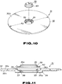
- Figure 10 is an exploded perspective view of a magneto-optical disc according to a second embodiment of the invention;
- Figure 11 is a cross-sectional view showing a disc substrate and a metal plate of the magneto-optical disc shown in Figure 10;
- Figure 12 is a schematic cross-sectional view showing a disc supporting table employed in a first embodiment of a method according to the invention;
- Figure 13 is a cross-sectional view showing a disc substrate attached to the disc supporting table shown in Figure 12;
- Figure 14 is a cross-sectional view showing a metal plate accommodated in a recess formed in a disc substrate by a method according to the second embodiment of the invention;
- Figure 15 is a cross-sectional view corresponding to Figure 14 showing a vibrator of an ultrasonic application device in contact with the rim of a recess of a disc substrate to accommodate a magnetic plate;
- Figure 16 is a cross-sectional view corresponding to Figure 14 showing a projection being formed on the rim of the recess in the disc substrate to accommodate the magnetic plate by application of ultrasonic vibrations;
- Figure 17 is a cross-sectional view corresponding to Figure 14 showing the magnetic metal plate attached to the disc substrate;
- Figure 18 is a plan view corresponding to Figure 17;
- Figure 19 is a cross-sectional view showing a disc substrate loaded on a disc supporting table employed in a second embodiment of a method according to the invention;
- Figure 20 is a cross-sectional view corresponding to Figure 19 showing a metal plate accommodated in a recess in the disc substrate;
- Figure 21 is a cross-sectional view corresponding to Figure 19 showing a vibrator of an ultrasonic application device in contact with a rim of the recess in the disc substrate;
- Figure 22 is a cross-sectional view corresponding to Figure 19 showing a projection formed on the rim of the recess in the disc substrate by application of ultrasonic vibrations;
- Figure 23 is a cross-sectional view corresponding to Figure 22 showing the magnetic metal plate attached to the disc substrate; and
- Figure 24 is a plan view corresponding to Figure 23.
- Referring to Figures 4, 5 and 6, a magneto-optical disc 1 includes a
disc substrate 2 formed of a synthetic resin, such as polycarbonate resin, in the shape of a disc. A signal recording layer for recording information signals is deposited on onemajor surface 2a of thedisc substrate 2. The othermajor surface 2b of thedisc substrate 2 opposite to said onemajor surface 2a provided with the deposited signal recording layer is a signal write/readout surface, and information signals may be recorded or reproduced by radiating a light beam on the signal recording layer from the side of the write/readout surface. - The
disc substrate 2 is of a thickness T₁ of about 1.2 mm and is formed with acentral hole 3 to be engaged by a centreing member provided centrally of a disc table of a rotating driving device provided within recording/reproducing apparatus. Thecentral hole 3 extends through thedisc substrate 2 with its centre coincident with the centre of curvature of a recording track(s) formed concentrically or spirally on the signal recording layer. - As shown in Figure 5, an
annular protuberance 4 is formed integrally at the centre of themajor surface 2b of thedisc substrate 2 and encircles thecentral hole 3. The function of theprotuberance 4 is to increase the depth of thecentre hole 3 in thethin disc substrate 2 to increase an amount of projection of the centreing member provided on the disc table with respect to thecentral hole 3 to ensure positive centreing operation of loading the magneto-optical disc 1 with the centre of rotation of the magneto-optical disc 1 coincident with the axis of the disc table. - The
protuberance 4 is formed in at least a non-recording region towards the radially inner side of thedisc substrate 2 free of the signal recording layer, and has an amount of axial projection substantially equal to the thickness T of thedisc substrate 2. Thus the portion of thedisc substrate 2 provided with theprotuberance 4 has a thickness twice that of the main substrate body. - An
annular recess 6 to accommodate amagnetic metal plate 5 is formed around thecentral hole 3 on themajor surface 2a of thedisc substrate 2. Therecess 6 has a diameter less than the outer diameter R₁ of theprotuberance 4 and a depth substantially equal to the thickness T of thedisc substrate 2. Therecess 6 has a diameter at anopen end 6a which is larger than at a bottom end to facilitate insertion of themetal plate 5 into therecess 6. - The bottom end of the
recess 6, operating as asetting surface 7 for themetal plate 5, is formed with astep 8. The function of thestep 8 is to prevent burrs or like projections from being formed on thesetting surface 7 for themetal plate 5 and to maintain planarity of the settingsurface 7. - The
metal plate 5, accommodated in therecess 6, is formed by punching a metal sheet, such as a stainless steel sheet, for example SUS-430, having a thickness of about 0.4 mm, into the shape of a disc. - The
metal plate 5 has the shape of a disc of a size that can be accommodated in therecess 6. Themetal plate 5 has its outer peripheral part bent so that the outer surface of a majormiddle part 5a is flush with themajor surface 2a of thedisc substrate 2 and an inner peripheral wall of theopen end 6a of therecess 6 is faced by the rim of themetal plate 5, as shown in Figure 6. That is, an outer part of themetal plate 5 is formed as arim flange 10 which lies on thesetting surface 7, which outer rim flange is joined to the central majormiddle part 5a by means of a frusto-conicalbent part 9. Thus themetal plate 5 is in the shape of a circular saucer, as shown in Figure 4. - The rim part of the
recess 6 is then thermally deformed at a plurality of positions, such as at four positions, to form projections 11 projecting into the interior of therecess 6. The projections 11 are formed by crushing and deforming part of the rim of therecess 6 so that the deformed portions project into the inside of therecess 6. Therefore, no projections are formed on themajor surface 2a of thedisc substrate 2, and indeed recesses 12 are formed in themajor surface 2a as a result of formation of the projections 11. - Since the projections 11 are formed in this manner, the
metal plate 5 has itsrim flange 10 supported by the projections 11, so that themetal plate 5 is fixed relative to thedisc substrate 2 by being accommodated and supported within therecess 6, as shown in Figures 7 and 8. - Although four such projections 11 are shown at equiangular intervals on the rim of the
recess 6 in Figure 8, it is only necessary for themetal plate 5 to be prevented from being dislocated from the inside of therecess 6 of thedisc substrate 2 and it would suffice to provide two or more projections 11. - Alternatively, an annular projection may be formed on the entire circumference of the
recess 6. - The projections 11 may be formed by applying a heated trowel or like heating means to desired portions of the rim of the
recess 6. - A swaging method by ultrasonic waves may instead be employed for forming the projections 11. For forming the projections 11 by the swaging method, a
contactor 21 of an ultrasonic welding device is engaged with the rim of therecess 6 thermally to deform portions of the rim of therecess 6 contacted by thecontactor 21 to cause these portions to project into therecess 6, as shown in Figure 9. - In a second embodiment of the invention shown in Figures 10 and 11, a magneto-
optical disc 31 includes adisc substrate 32 formed by moulding a transparent synthetic resin material, such as polycarbonate resin. The disc substrate is in the form of a disc having a radius R₂ equal to about 64 mm and a thickness T₂ equal to about 1.2 mm. - The magneto-
optical disc 31, including thedisc substrate 32, has a signal recording part formed by depositing a signal recording layer on onemajor surface 32a of thedisc substrate 32, with the oppositemajor surface 32b being a signal write/readout surface. A light beam is radiated on the signal recording layer from the write/read surface to record/reproduce information signals. - A
central hole 33, engaged by a centreing member provided at the middle of a disc table of a disc rotating and driving device provided within recording/reproducing apparatus, extends through the centre of thedisc substrate 32 of the magneto-optical disc 31. Thecentral hole 33 is formed as a through-hole in thedisc substrate 2 so that the centre thereof is coincident with a recording track(s) formed concentrically or spirally on the signal recording layer. - An
annular protuberance 34 is formed at the centre of the oppositemajor surface 32b of thedisc substrate 32 to encircle thecentral hole 33. The function of theprotuberance 34 is to increase the depth of thecentral hole 33 in thethin disc substrate 32 to increase an amount of projection of the centreing member of the disc table into thecentral hole 33 to ensure correct alignment of the centre of rotation of the magneto-optical disc 31 with the axis of the disc table during loading of the magneto-optical disc 31 onto the disc table. The end face of theprotuberance 34 also functions as a loading reference plane with respect to the disc table. - The
protuberance 34 is formed in a non-recording radially inner region of thedisc substrate 32 free of the signal recording layer, and projects by an amount substantially equal to the thickness T₂ of thedisc substrate 32. Thus the portion of thedisc substrate 32 formed with theprotuberance 34 has a thickness which is twice that of the main body of thedisc substrate 32. - An
annular recess 36 to accommodate amagnetic metal plate 35 is formed around thecentral hole 33 on themajor surface 32a of thedisc substrate 32. Therecess 36 has a diameter less than the outer diameter r of theprotuberance 34 and a depth substantially equal to the thickness T₂ of thedisc substrate 32. Therecess 36 has a diameter larger at anopen end 36a thereof than that at the bottom end thereof to facilitate insertion of themetal plate 35 into therecess 36. - The
major surface 32a of thedisc substrate 32 presents a planar surface except at therecess 36. - The bottom end of the
recess 36, operating as a settingsurface 37 for the metal plate 25, is formed with astep 38. The function of thestep 38 is to prevent burrs or like projections from being formed on the settingsurface 37 for themetal plate 35 and to maintain planarity of the settingsurface 37. - The
metal plate 35, accommodated in therecess 36, is formed by punching a metal sheet, such as a stainless steel sheet, e.g. SUS-430, having a thickness of about 0.4 mm, into the shape of a disc, as shown in Figure 10. - Referring to Figure 10, the
metal plate 35 has the shape of a disc of a size that can be accommodated in therecess 36. Themetal plate 35 has its outer peripheral part bent so that a majormiddle part 35a is flush with themajor surface 32a of thedisc substrate 32 and an inner peripheral wall of theopen end 36a of therecess 36 is faced by the rim of themetal plate 35. That is, anouter rim flange 40 of themetal plate 35 is formed as a setting area for the settingsurface 37 and merges with the majormiddle part 35a by means of a frusto-conicalbent part 39. Thus themetal plate 5 is in the shape of a dished circular saucer, as shown in Figure 10. - The
metal plate 35, formed as described above, is retained with respect to thedisc substrate 32 by the following process and method. - The
disc substrate 32, formed as shown in Figures 10 and 11, is first set on a suction support table 51, Figure 12. - The suction support table 51, which can position and support the
disc substrate 32 set thereon by suction, is provided with a substrate support table 53 to position and set thedisc substrate 32 on the upper surface of asupport table body 52, as shown in Figure 12. The support table 53 has acentral projection 54 to be engaged in thecentral hole 33 of thedisc substrate 32 and arecess 55 around theprojection 54 which recess is to be engaged by theprotuberance 34 of thedisc substrate 32. - A soft
protective sheet 56 of for example silicon rubber is bonded to a setting surface of the substrate support table 53 in contact with themajor surface 32b of thedisc substrate 32. Theprotective sheet 56 is provided to prevent damages to themajor surface 32b of thedisc substrate 32. - Suction means is provided to support the
disc substrate 32 set on the substrate support table 53 by suction under vacuum by a vacuum pump, not shown, provided on the suction support table 51. The suction means includes a plurality ofsuction ports 57 formed in the substrate support table 53 and a plurality ofspacers 60 interposed between the substrate support table 53 and thesupport table body 52 to define asuction air chamber 58 so that air contained in thesuction air chamber 58 is drawn by a vacuum pump, not shown, via anair passage 59 formed in thesupport table body 52, to suck down onto and support thedisc substrate 32 on the substrate support table 53. - The
suction ports 57 are provided in the substrate support table 53 in register with an outer peripheral region and the central region of thedisc substrate 32 placed thereon and within therecess 55 engaged with theprotuberance 34. By providing the suction ports at these positions, thedisc substrate 32 may be pressed and supported substantially uniformly over its entire surface against the substrate support table 53. - Meanwhile, ports communicating with these
suction ports 57 are formed in theprotective sheet 56 in register with thesuction ports 57. - Referring to Figure 13, the
disc substrate 32 is placed on the suction support table 51 so that therecess 36 in themetal plate 35 is directed upwards. Thedisc substrate 32 is loaded with thecentral hole 33 engaged by theprojection 54 and with theprotuberance 34 engaged in therecess 55 so as to be positioned with respect to the suction support table 51. - With the
disc substrate 32 thus set on the suction support table 51, the vacuum pump is set into operation to suck out the air contained in thesuction chamber 58 via theair passage 58. At this time, the air contained between thedisc substrate 32 and the suction support table 51 is sucked via thesuction ports 57 so that thedisc substrate 32 is tightly supported against theprotective sheet 56 on the suction support table 51. - Since the
disc substrate 32 is supported at this time on the suction support table 56 with thecentral hole 33 engaged by theprojection 54 and with theprotuberance 34 engaged in therecess 55, thedisc substrate 32 is loaded in position on the suction support table 56. - After the
disc substrate 32 is loaded in this manner on the suction support table 51, themetal plate 35 is accommodated in therecess 36 with therim flange 40 forming the setting area thereof set on the settingsurface 37 of therecess 36. - After the
metal plate 35 is placed within therecess 36, avibrator 62 as a resonator of an ultrasonicwave application device 61 has its tip placed in contact with the rim of therecess 36 to impress ultrasonic waves having a plane of oscillation in a direction parallel to the major surface of thedisc substrate 32, as shown in Figure 15. It should be noted that, during application of ultrasonic oscillations to thedisc substrate 32, theultrasonic vibrator 62 is pressed with a predetermined pressure against thedisc substrate 32. - When the ultrasonic vibrations are applied in this manner, the rim part of the
recess 36 in contact with thevibrator 62 is heated and softened. Since thevibrator 62 is pressed with a predetermined pressure from above, a recessedarea 42 corresponding in size to thevibrator 62 is formed around the rim of therecess 36 and correspondingly alug 41 is formed which projects towards the inner region of therecess 36. As shown in Figure 16, thelug 41 protrudes above therim flange 40 of themetal plate 35 placed in therecess 36 and supports therim flange 40. - Since the ultrasonic vibrations are applied to the
disc substrate 32 in a direction parallel to themajor surface 32a of thedisc substrate 32, the ultrasonic vibrations are transmitted in a direction parallel to themajor surface 32a of thedisc substrate 32, so that the portions of thedisc substrate 32 softened by being contacted with the vibrator of thedisc substrate 32 is displaced in a direction parallel to themajor surface 32a along which the ultrasonic vibrations are transmitted. The result is that thelugs 41 formed on the rim of therecess 36 protrude positively towards the inner region of therecess 36 and overlie therim flange 40 of themetal plate 35. - Preferably, the ultrasonic vibrations applied to the
disc substrate 32 are produced in a direction parallel to themajor surface 32a of thedisc substrate 32, so that only small vibrations are transmitted along the thickness of thedisc substrate 32. The result is that heating of the disc substrate in a direction along its thickness is limited to inhibit deformation of therecess 36 in the same direction. In this manner, each of thelugs 41 which extends towards the inner region of therecess 36 may have a controlled thickness to enable thelug 41 to support therim flange 40 of themetal plate 35 without making contact with therim flange 40. That is, by setting the depth d of therecess 36 so as to be larger than the thickness of themetal plate 35, a gap w may be left between thelug 41 and therim flange 40, as shown in Figure 17, so as loosely to accommodate and hold themetal plate 35 within therecess 36. - By loosely fitting and supporting the
metal plate 35 in therecess 36 in this manner, it becomes possible to prevent themetal plate 35 from being fixed with a tilt relative to the major surface of thedisc substrate 32 as well as to prevent thedisc substrate 35 of synthetic resin from being deformed due to differences in thermal expansion coefficient between themetal plate 35 and thedisc substrate 32. - By providing the
lugs 41, formed by applying ultrasonic vibrations in a direction parallel to themajor surface 32a of thedisc substrate 32, at a plurality of positions, such as four positions, symmetrically on the rim of therecess 36, themetal plate 35 accommodated within therecess 36 may be supported by thelugs 41 and thereby retained by thedisc substrate 2. - By simultaneously contacting
oscillators 62 on the rim of therecess 36, a plurality oflugs 41 may be formed at the same time. - It is noted that the size of the
oscillator 62 contacted with the rim of therecess 36 for forming thelug 41 is set by the desired size of thelug 4. - The ultrasonic vibrations to be applied to the
disc substrate 32 of a polycarbonate resin, are preferably within the range 15 to 50 kHz. If the oscillation frequency is not more than 15 kHz, sufficient heating may not be achieved, whereas, if the oscillation frequency is over 50 kHz, the degree of softening of the portions of the disc substrate to be contacted with theoscillator 62 and thereby softened is difficult to control because of excessive heating. The ultrasonic vibrations are preferably at about 20 kHz. - Although four of the
lugs 41 are shown formed symmetrically at equiangular intervals on the rim of therecess 36 in Figure 18, it is only necessary that themetal plate 35 be supported by thedisc substrate 31 so as not to be detached from therecess 36, so that it suffices to provide two or more lugs at appropriate positions on the rim of therecess 36. - The
metal plate 35 held by thedisc substrate 32 may be in the form of a flat disc of a size to be accommodated within therecess 36, instead of being dished so as to have therim flange 40. - In a third embodiment of the invention hereinafter described parts or components similar to those of the preceding embodiments are denoted by the same reference numerals and detailed description therefor is omitted for simplicity.
- After loading the
disc substrate 32 on the suction support table 51, as shown in Figure 19, themetal plate 35 is placed within therecess 36. At this time, themetal plate 35 is placed in therecess 3 with therim flange 40 thereof resting on the settingsurface 37 of therecess 36, as shown in Figure 20. - After the
metal plate 35 has been placed within therecess 36, anoscillator 72, operating as a resonator of anultrasonic vibrator 71, has its tip contacted with the rim of therecess 36, as shown in Figure 21, and ultrasonic vibrations are applied in a direction perpendicular to the major surface of thedisc substrate 32. It is noted that, when the ultrasonic vibrations are applied to thedisc substrate 32, theoscillator 72 is pressed against thedisc substrate 32 with a determined pressure. - By application of the ultrasonic vibrations in this manner, the rim portions of the
recess 36 contacted by theoscillator 72 are heated and softened. Since theoscillator 72 is pressed at this time with a predetermined pressure, a recessedarea 42 of a size corresponding to that of theoscillator 72 is formed in the rim part of therecess 36, and correspondingly, alug 43 is formed which projects into the inside of therecess 36. As shown in Figure 22, thelug 43 protrudes above therim flange 40 of themetal plate 35 to support therim flange 40. - Since the ultrasonic vibrations applied to the
disc substrate 32 are produced in a direction perpendicular to the major surface of thedisc substrate 32, the vibrations are propagated in a direction along the thickness of thedisc substrate 32. Conversely, only small vibrations are propagated in a direction along themajor surface 32a of thedisc substrate 32. The result is that thedisc substrate 32 is softened mainly in the direction along the depth of the portions thereof contacted with theoscillator 72, while softening thereof in the direction along themajor surface 32a is restricted. In this manner, thelug 43 may be formed with a size corresponding to the size of thevibrator 72. - By providing the
lugs 43, formed by applying ultrasonic vibrations in a direction perpendicular to themajor surface 32a of thedisc substrate 32, at a plurality of positions, such as four positions, symmetrically on the rim of therecess 36, themetal plate 35 accommodated within therecess 36 may be supported by thelugs 43 and thereby retained by thedisc substrate 32. - It is noted that the size of the
oscillator 72 contacted with the rim of therecess 36 for forming thelugs 43 is set by the desired size of thelug 43. - The ultrasonic vibrations to be applied to the
disc substrate 32 of a polycarbonate resin, are preferably within the range of 15 to 40 kHz. If the oscillation frequency is less than 15 kHz, sufficient heating may not be achieved, whereas, if the oscillation frequency is higher than 40 kHz, the degree of softening of the portions of the disc substrate to be contacted with theoscillator 72 and thereby softened is difficult to control because of excessive heating. The ultrasonic vibrations are preferably about 20 kHz. - Although four of the
lugs 41 are shown formed symmetrically at equiangular intervals on the rim of therecess 36 in Figure 24, it is only necessary that themetal plate 35 be supported by thedisc substrate 31 without being detached from therecess 36, so that it suffices to provide two or more lugs at appropriate positions on the rim of therecess 36. - A single
annular lug 43 may also be provided around the entire circumference of therecess 36, in which case theoscillator 72 is in the form of a ring corresponding to the rim of therecess 36. - The
metal plate 35 held by thedisc substrate 32 may be in the form of a flat disc of a size to be accommodated within therecess 36, instead of being dished so as to have therim flange 40 as in the present embodiment. - In addition, although the disc is a magneto-optical disc in the above-described embodiments, the invention may be applied to a disc for recording information signals which is provided with a disc substrate of synthetic resin and a magnetic plate for magnetically chucking the disc.
Claims (20)
- An optical disc comprising
a disc substrate (2, 32) having a central hole (3, 33) and a recess (6, 36) in one major surface (2a, 32a) thereof, the recess (6, 36) having its centre substantially coaxial with the centre of the central hole (3, 33),
a magnetic member (5, 35) engaged in the recess (6, 36) in the disc substrate, and
one or more lugs (11, 41, 43) protruding from said one major surface (2a, 32a) of the disc substrate (2, 32) into the recess (6, 36). - An optical disc according to claim 1, wherein the recess (6, 36) is formed with a step (8, 38) connecting to said one major surface (2a, 32a) of the disc substrate (2, 32).
- An optical disc according to claim 1, wherein the distance between the bottom of the recess (6, 36) and the lug of lugs (11, 41, 43) is selected to be larger than the thickness of an outer rim part (10, 40) of the magnetic member (5, 35).
- An optical disc according to claim 3, wherein the magnetic member (5, 35) is in the form of a disc of a diameter less than the inner diameter of the recess (6, 36).
- An optical disc comprising
a disc substrate (2, 32) having a protuberance (4, 34) on a major surface (2b, 32b) thereof to surround a central hole (3, 33) and a recess (6, 36) in the opposite major surface (2a, 32a) thereof having its centre substantially coaxial with the centre of the central hole (3, 33),
a magnetic member (5, 35) engaged in the recess (6, 36) in the disc substrate (2, 32), and
one or more lugs (11, 41, 43) protruding from said opposite major surface (2a, 32a) of the disc substrate into the recess (6, 36). - An optical disc according to claim 5, wherein the recess (6, 36) is formed with a step (8, 38) connecting to said opposite major surface of the disc substrate.
- An optical disc according to claim 5, wherein the distance between the bottom of the recess (6, 36) and the lug or lugs (11, 41, 43) is selected to be larger than the thickness of an outer rim part (10, 40) of the magnetic member (5, 35).
- An optical disc according to claim 7, wherein the magnetic member (5, 35) is in the form of a disc of a diameter less than the inner diameter of the recess (6, 36).
- An optical disc comprising
a disc substrate (2, 32) having a protuberance (4, 34) on a major surface (2b, 32b) thereof surrounding a central hole (3, 33) and a recess (6, 36) in the opposite major surface (2a, 32a) thereof having a centre substantially coaxial with the centre of the central hole (3 33), and
a magnetic member (5, 35) comprising a major middle part (5a, 35a) and a rim flange (10, 40) at the outer periphery, the rim flange (10, 40) being parallel to the major middle part (5a, 35a) and connected thereto by a frusto-conical part (9, 39), the magnetic member (5, 35) being placed within the recess (6, 36), and
one or more lugs (11, 41, 43) protruding from said opposite major surface (2a, 32a) of the disc substrate (2, 32) into the recess (6, 36) to overlie a part of rim flange (10, 40). - An optical disc according to claim 9, wherein the recess (6, 36) is formed with a step (8, 38) connecting to the opposite major surface (2a, 32a) of the disc substrate.
- An optical disc according to claim 9, wherein the distance between the bottom of the recess (6, 36) and the lug (11, 41, 43) is selected to be larger than the thickness of the rim flange (10, 40) of the magnetic member (5, 35).
- An optical disc according to claim 11, wherein the magnetic member (5, 35) is in the form of a disc of a diameter less than the inner diameter of the recess (6, 36).
- A method of holding a magnetic member (5, 35) by a disc substrate (2, 32) exhibiting light transmitting properties and having a central hole (3, 33) and a recess (6, 36) in one major surface (2a, 32a) thereof, the recess (6, 36) having the centre substantially coaxial with the centre of said central hole (3, 33), the method comprising
engaging the magnetic member (5, 35) in the recess (6, 36) of the disc substrate (2, 32), and
applying, with the magnetic member (6, 36) engaged in the recess, ultrasonic vibrations to the rim part of the recess (6, 36) of the disc substrate (2, 32) by ultrasonic wave generating means (21, 62), while the ultrasonic wave generating means (21, 62) is pressed against the disc substrate, thereby thermally to deform the rim part of the recess of the disc substrate to hold the magnetic member (5, 35) by the disc substrate. - A method according to claim 13, wherein the ultrasonic vibrations generated by the ultrasonic wave generating means (21, 62) are vibrations having the plane of vibration in a direction parallel to the major surfaces (2a, 32a) of the disc substrate (2, 32).
- A method according to claim 13, wherein the ultrasonic vibrations generated by the ultrasonic wave generating means (21, 62) are vibrations having the plane of vibration in a direction perpendicular to the major surfaces (2a, 32a, 26, 32b) of the disc substrate (2, 32).
- A method according to claim 13, wherein the ultrasonic vibrations by the ultrasonic vibrator is in the range of from 15 to 50 kHz.
- A method of holding a magnetic member (5, 35) by a disc substrate (2, 32) exhibiting light transmitting properties and having a central opening (3, 33) and a recess (6, 36) in one major surface (2a, 32a) thereof, the recess (6, 36) having its centre substantially coaxial with the centre of the central hole (3, 33), the method comprising employing
means (51 to 60) to hold the disc substrate (2, 32) in a positioned state, and
ultrasonic wave generating means (21, 62) to apply ultrasonic vibrations to the rim part of the recess (6, 36) of the disc substrate while the magnetic member (5, 35) is engaged in the recess (6, 36) of the disc substrate (2, 32) held by the holding means (51 to 60). - A method according to claim 17, wherein the ultrasonic vibrations generated by the ultrasonic wave generating means (21, 62) are vibrations having the plane of vibration in a direction parallel to the major surfaces (2a, 32a, 2b, 32b) of the disc substrate (2, 32).
- A method according to claim 17, wherein the ultrasonic vibrations generated by the ultrasonic wave generating means are vibrations having the plane of vibration in a direction perpendicular to the major surfaces of the disc substrate.
- A method according to claim 17, wherein the ultrasonic vibrations by the ultrasonic vibrator are in the range of from 15 to 50 kHz.
Applications Claiming Priority (6)
| Application Number | Priority Date | Filing Date | Title |
|---|---|---|---|
| JP3185132A JP2959208B2 (en) | 1991-06-29 | 1991-06-29 | Information signal recording disk |
| JP185132/91 | 1991-06-29 | ||
| JP59616/92 | 1992-02-14 | ||
| JP05961592A JP3237171B2 (en) | 1992-02-14 | 1992-02-14 | Method of holding magnetic plate to disk substrate |
| JP05961692A JP3237172B2 (en) | 1992-02-14 | 1992-02-14 | Method of holding magnetic plate to disk substrate |
| JP59615/92 | 1992-02-14 |
Publications (3)
| Publication Number | Publication Date |
|---|---|
| EP0521654A2 true EP0521654A2 (en) | 1993-01-07 |
| EP0521654A3 EP0521654A3 (en) | 1993-06-09 |
| EP0521654B1 EP0521654B1 (en) | 1997-11-05 |
Family
ID=27296942
Family Applications (1)
| Application Number | Title | Priority Date | Filing Date |
|---|---|---|---|
| EP92305850A Expired - Lifetime EP0521654B1 (en) | 1991-06-29 | 1992-06-25 | Disc for recording information signals |
Country Status (10)
| Country | Link |
|---|---|
| US (1) | US5323381A (en) |
| EP (1) | EP0521654B1 (en) |
| KR (1) | KR100254507B1 (en) |
| AT (1) | ATE160046T1 (en) |
| AU (1) | AU666307B2 (en) |
| CA (1) | CA2072056C (en) |
| DE (1) | DE69222986T2 (en) |
| MY (1) | MY107834A (en) |
| PH (1) | PH30511A (en) |
| TW (1) | TW207582B (en) |
Families Citing this family (24)
| Publication number | Priority date | Publication date | Assignee | Title |
|---|---|---|---|---|
| JP3384002B2 (en) * | 1992-01-24 | 2003-03-10 | ソニー株式会社 | Disc table and recording and / or reproducing apparatus |
| AU665947B2 (en) * | 1991-05-29 | 1996-01-25 | Sony Corporation | Optical disc and method for producing the optical disc |
| DE69319663T2 (en) * | 1992-05-26 | 1998-11-19 | Sony Corp | Method of mounting a magnetic disk on a disk substrate |
| JPH064908A (en) * | 1992-06-22 | 1994-01-14 | Awa Eng Co | Optical disk and apparatus for production thereof |
| DE19631319A1 (en) * | 1995-08-15 | 1997-02-20 | Minnesota Mining & Mfg | Optical disc for digital data recording |
| KR100268492B1 (en) * | 1996-01-11 | 2000-10-16 | 윤종용 | Hard disk drive media |
| US5725934A (en) * | 1996-03-12 | 1998-03-10 | Disc Concepts, Inc. | Mountable disc display device |
| US6013352A (en) * | 1996-03-12 | 2000-01-11 | Gallant; Glenn | Mountable disc display device |
| JPH10269621A (en) * | 1997-03-25 | 1998-10-09 | Sony Corp | Optical disk substrate and optical disk using the substrate |
| US6154441A (en) * | 1997-04-17 | 2000-11-28 | Imation Corp. | Method for centering a hub in an optical disc, and an optical storage system using such disc |
| GB2340654A (en) * | 1997-06-03 | 2000-02-23 | Seagate Technology | Optical disc for optical storage system |
| US6122145A (en) * | 1997-10-15 | 2000-09-19 | B.E. Technology, Llc | Computer diskette with insertable multi-piece media |
| JP2000048513A (en) * | 1998-07-24 | 2000-02-18 | Sony Corp | Center core of disclike recording medium and its manufacture |
| US6205113B1 (en) * | 1998-08-18 | 2001-03-20 | Iomega Corporation | Plastic clamp with hub and platter for use in disc drive |
| WO2000028538A1 (en) * | 1998-11-06 | 2000-05-18 | Hitachi Maxell, Ltd. | Optical disk, disk substrate, and drive |
| US6078341A (en) * | 1998-12-14 | 2000-06-20 | Xerox Corporation | Laser diode raster output scanners with interlaced scan lines |
| US6817026B2 (en) * | 2000-04-28 | 2004-11-09 | Dphi Acquisitions, Inc. | Magnetic hub assembly for data storage disk |
| US6690642B2 (en) * | 2000-05-17 | 2004-02-10 | Computech International Ventures Limited | Optical disk |
| TW591625B (en) * | 2002-01-15 | 2004-06-11 | Benq Corp | Apparatus for reducing tray-in noise |
| WO2004013844A2 (en) * | 2002-07-30 | 2004-02-12 | Koninklijke Philips Electronics N.V. | Disc drive apparatus |
| KR100499479B1 (en) * | 2002-09-10 | 2005-07-05 | 엘지전자 주식회사 | Digital Versatile Disc of high density |
| US7757247B2 (en) * | 2004-12-08 | 2010-07-13 | Electronics And Telecommunications Research Institute | Small form factor optical/magnetic disk for information storage |
| KR101339923B1 (en) * | 2011-11-03 | 2013-12-10 | 삼성전자주식회사 | Disk and test apparatus including the disk |
| USD734341S1 (en) * | 2012-08-06 | 2015-07-14 | Panasonic Intellectual Property Management Co., Ltd. | Optical disk |
Citations (5)
| Publication number | Priority date | Publication date | Assignee | Title |
|---|---|---|---|---|
| DE2624375A1 (en) * | 1976-05-31 | 1977-12-15 | Polygram Gmbh | Heat-curable plate for picture or video signals - with central circular recess contg. flat ring, to eliminate surface deformation |
| EP0233644A2 (en) * | 1986-02-20 | 1987-08-26 | Sony Corporation | An optical recording disc |
| JPS63129578A (en) * | 1986-11-19 | 1988-06-01 | Matsushita Electric Ind Co Ltd | Disk like recording medium |
| US4787009A (en) * | 1986-06-26 | 1988-11-22 | Sony Corporation | Optical disk |
| EP0314010A2 (en) * | 1987-10-27 | 1989-05-03 | Seiko Epson Corporation | Information recording disk |
Family Cites Families (6)
| Publication number | Priority date | Publication date | Assignee | Title |
|---|---|---|---|---|
| EP0278358B1 (en) * | 1987-02-06 | 1994-07-20 | Sony Corporation | Disk for recording and/or reproducing apparatus having magnetic chucking device |
| JPS63249985A (en) * | 1987-04-06 | 1988-10-17 | Sony Corp | Disk device |
| US5010435A (en) * | 1987-12-03 | 1991-04-23 | Tdk Corporation | Hub for a disk type recording medium |
| US4944982A (en) * | 1988-04-04 | 1990-07-31 | Fuji Photo Film Co., Ltd. | Information recording medium having magnetizable hub |
| US4941066A (en) * | 1988-05-11 | 1990-07-10 | Shape Inc. | Injection molded center core for a recording disc and related method of manufacture |
| US4983439A (en) * | 1988-05-12 | 1991-01-08 | Fuji Photo Film Co., Ltd. | Method of manufacturing a recording medium and recording medium |
-
1992
- 1992-06-11 TW TW081104589A patent/TW207582B/zh active
- 1992-06-16 MY MYPI92001024A patent/MY107834A/en unknown
- 1992-06-23 CA CA002072056A patent/CA2072056C/en not_active Expired - Lifetime
- 1992-06-24 AU AU18555/92A patent/AU666307B2/en not_active Expired
- 1992-06-25 US US07/904,159 patent/US5323381A/en not_active Expired - Lifetime
- 1992-06-25 EP EP92305850A patent/EP0521654B1/en not_active Expired - Lifetime
- 1992-06-25 DE DE69222986T patent/DE69222986T2/en not_active Expired - Lifetime
- 1992-06-25 AT AT92305850T patent/ATE160046T1/en active
- 1992-06-26 PH PH44571A patent/PH30511A/en unknown
- 1992-06-26 KR KR1019920011188A patent/KR100254507B1/en not_active IP Right Cessation
Patent Citations (5)
| Publication number | Priority date | Publication date | Assignee | Title |
|---|---|---|---|---|
| DE2624375A1 (en) * | 1976-05-31 | 1977-12-15 | Polygram Gmbh | Heat-curable plate for picture or video signals - with central circular recess contg. flat ring, to eliminate surface deformation |
| EP0233644A2 (en) * | 1986-02-20 | 1987-08-26 | Sony Corporation | An optical recording disc |
| US4787009A (en) * | 1986-06-26 | 1988-11-22 | Sony Corporation | Optical disk |
| JPS63129578A (en) * | 1986-11-19 | 1988-06-01 | Matsushita Electric Ind Co Ltd | Disk like recording medium |
| EP0314010A2 (en) * | 1987-10-27 | 1989-05-03 | Seiko Epson Corporation | Information recording disk |
Non-Patent Citations (1)
| Title |
|---|
| PATENT ABSTRACTS OF JAPAN vol. 12, no. 388 (P-771)(3235) 17 October 1988 & JP-A-63 129 578 ( MATSUSHITA ELECTRIC IND. CO. LTD. ) 1 June 1988 * |
Also Published As
| Publication number | Publication date |
|---|---|
| CA2072056C (en) | 2001-09-04 |
| DE69222986T2 (en) | 1998-04-09 |
| KR100254507B1 (en) | 2000-05-01 |
| MY107834A (en) | 1996-06-29 |
| AU1855592A (en) | 1993-01-07 |
| TW207582B (en) | 1993-06-11 |
| EP0521654B1 (en) | 1997-11-05 |
| ATE160046T1 (en) | 1997-11-15 |
| CA2072056A1 (en) | 1992-12-30 |
| KR930001145A (en) | 1993-01-16 |
| US5323381A (en) | 1994-06-21 |
| AU666307B2 (en) | 1996-02-08 |
| PH30511A (en) | 1997-06-13 |
| DE69222986D1 (en) | 1997-12-11 |
| EP0521654A3 (en) | 1993-06-09 |
Similar Documents
| Publication | Publication Date | Title |
|---|---|---|
| EP0521654B1 (en) | Disc for recording information signals | |
| US4785444A (en) | Optical recording disc | |
| EP0516329B1 (en) | Optical disc and method for producing the optical disc | |
| EP0572153B1 (en) | Method for mounting magnetic plate on a disc substrate | |
| US4827470A (en) | Information memory medium | |
| US4866697A (en) | Information memory medium | |
| JP2593482B2 (en) | optical disk | |
| JP3237172B2 (en) | Method of holding magnetic plate to disk substrate | |
| JP3237199B2 (en) | How to attach a magnetic plate to a disk substrate | |
| JP3211390B2 (en) | Method of holding magnetic plate to disk substrate | |
| JP3237171B2 (en) | Method of holding magnetic plate to disk substrate | |
| JPH0628806A (en) | Method for holding magnetic plate on disk substrate | |
| JP2674067B2 (en) | optical disk | |
| JPH05325466A (en) | Method and device for attaching magnetic plate to disk substrate | |
| JP2959208B2 (en) | Information signal recording disk | |
| JPH05325468A (en) | Method for attaching magnetic plate to disk substrate | |
| JP3072658B2 (en) | Information signal recording disk | |
| JP3287004B2 (en) | Disc for recording information signals | |
| JPH08329531A (en) | Disk device | |
| JPH0660433A (en) | Information signal recording disk | |
| JP2000057726A (en) | Disk hub | |
| JPH03266271A (en) | Fitting structure for hub for disk | |
| JPH0554583A (en) | Disk cartridge | |
| JPH06290491A (en) | Disk base and die unit for molding disk base | |
| JPH08221807A (en) | Optical recording medium and its production |
Legal Events
| Date | Code | Title | Description |
|---|---|---|---|
| PUAI | Public reference made under article 153(3) epc to a published international application that has entered the european phase |
Free format text: ORIGINAL CODE: 0009012 |
|
| AK | Designated contracting states |
Kind code of ref document: A2 Designated state(s): AT DE FR GB NL |
|
| PUAL | Search report despatched |
Free format text: ORIGINAL CODE: 0009013 |
|
| AK | Designated contracting states |
Kind code of ref document: A3 Designated state(s): AT DE FR GB NL |
|
| 17P | Request for examination filed |
Effective date: 19931103 |
|
| 17Q | First examination report despatched |
Effective date: 19950907 |
|
| GRAG | Despatch of communication of intention to grant |
Free format text: ORIGINAL CODE: EPIDOS AGRA |
|
| GRAH | Despatch of communication of intention to grant a patent |
Free format text: ORIGINAL CODE: EPIDOS IGRA |
|
| GRAH | Despatch of communication of intention to grant a patent |
Free format text: ORIGINAL CODE: EPIDOS IGRA |
|
| GRAA | (expected) grant |
Free format text: ORIGINAL CODE: 0009210 |
|
| AK | Designated contracting states |
Kind code of ref document: B1 Designated state(s): AT DE FR GB NL |
|
| REF | Corresponds to: |
Ref document number: 160046 Country of ref document: AT Date of ref document: 19971115 Kind code of ref document: T |
|
| REF | Corresponds to: |
Ref document number: 69222986 Country of ref document: DE Date of ref document: 19971211 |
|
| ET | Fr: translation filed | ||
| PLBE | No opposition filed within time limit |
Free format text: ORIGINAL CODE: 0009261 |
|
| STAA | Information on the status of an ep patent application or granted ep patent |
Free format text: STATUS: NO OPPOSITION FILED WITHIN TIME LIMIT |
|
| 26N | No opposition filed | ||
| REG | Reference to a national code |
Ref country code: GB Ref legal event code: IF02 |
|
| REG | Reference to a national code |
Ref country code: GB Ref legal event code: 746 Effective date: 20091124 |
|
| PGFP | Annual fee paid to national office [announced via postgrant information from national office to epo] |
Ref country code: FR Payment date: 20110630 Year of fee payment: 20 |
|
| PGFP | Annual fee paid to national office [announced via postgrant information from national office to epo] |
Ref country code: NL Payment date: 20110621 Year of fee payment: 20 Ref country code: GB Payment date: 20110620 Year of fee payment: 20 Ref country code: AT Payment date: 20110613 Year of fee payment: 20 |
|
| PGFP | Annual fee paid to national office [announced via postgrant information from national office to epo] |
Ref country code: DE Payment date: 20110622 Year of fee payment: 20 |
|
| REG | Reference to a national code |
Ref country code: DE Ref legal event code: R071 Ref document number: 69222986 Country of ref document: DE |
|
| REG | Reference to a national code |
Ref country code: DE Ref legal event code: R071 Ref document number: 69222986 Country of ref document: DE |
|
| REG | Reference to a national code |
Ref country code: NL Ref legal event code: V4 Effective date: 20120625 |
|
| REG | Reference to a national code |
Ref country code: GB Ref legal event code: PE20 Expiry date: 20120624 |
|
| PG25 | Lapsed in a contracting state [announced via postgrant information from national office to epo] |
Ref country code: DE Free format text: LAPSE BECAUSE OF EXPIRATION OF PROTECTION Effective date: 20120626 |
|
| PG25 | Lapsed in a contracting state [announced via postgrant information from national office to epo] |
Ref country code: GB Free format text: LAPSE BECAUSE OF EXPIRATION OF PROTECTION Effective date: 20120624 |
|
| REG | Reference to a national code |
Ref country code: AT Ref legal event code: MK07 Ref document number: 160046 Country of ref document: AT Kind code of ref document: T Effective date: 20120625 |