EP0233644A2 - An optical recording disc - Google Patents
An optical recording disc Download PDFInfo
- Publication number
- EP0233644A2 EP0233644A2 EP87102307A EP87102307A EP0233644A2 EP 0233644 A2 EP0233644 A2 EP 0233644A2 EP 87102307 A EP87102307 A EP 87102307A EP 87102307 A EP87102307 A EP 87102307A EP 0233644 A2 EP0233644 A2 EP 0233644A2
- Authority
- EP
- European Patent Office
- Prior art keywords
- hub
- disc
- optical recording
- set forth
- recording disc
- Prior art date
- Legal status (The legal status is an assumption and is not a legal conclusion. Google has not performed a legal analysis and makes no representation as to the accuracy of the status listed.)
- Granted
Links
Images


Classifications
-
- G—PHYSICS
- G11—INFORMATION STORAGE
- G11B—INFORMATION STORAGE BASED ON RELATIVE MOVEMENT BETWEEN RECORD CARRIER AND TRANSDUCER
- G11B7/00—Recording or reproducing by optical means, e.g. recording using a thermal beam of optical radiation by modifying optical properties or the physical structure, reproducing using an optical beam at lower power by sensing optical properties; Record carriers therefor
- G11B7/24—Record carriers characterised by shape, structure or physical properties, or by the selection of the material
- G11B7/241—Record carriers characterised by shape, structure or physical properties, or by the selection of the material characterised by the selection of the material
- G11B7/252—Record carriers characterised by shape, structure or physical properties, or by the selection of the material characterised by the selection of the material of layers other than recording layers
-
- B—PERFORMING OPERATIONS; TRANSPORTING
- B29—WORKING OF PLASTICS; WORKING OF SUBSTANCES IN A PLASTIC STATE IN GENERAL
- B29C—SHAPING OR JOINING OF PLASTICS; SHAPING OF MATERIAL IN A PLASTIC STATE, NOT OTHERWISE PROVIDED FOR; AFTER-TREATMENT OF THE SHAPED PRODUCTS, e.g. REPAIRING
- B29C66/00—General aspects of processes or apparatus for joining preformed parts
- B29C66/40—General aspects of joining substantially flat articles, e.g. plates, sheets or web-like materials; Making flat seams in tubular or hollow articles; Joining single elements to substantially flat surfaces
- B29C66/47—Joining single elements to sheets, plates or other substantially flat surfaces
- B29C66/474—Joining single elements to sheets, plates or other substantially flat surfaces said single elements being substantially non-flat
-
- B—PERFORMING OPERATIONS; TRANSPORTING
- B29—WORKING OF PLASTICS; WORKING OF SUBSTANCES IN A PLASTIC STATE IN GENERAL
- B29C—SHAPING OR JOINING OF PLASTICS; SHAPING OF MATERIAL IN A PLASTIC STATE, NOT OTHERWISE PROVIDED FOR; AFTER-TREATMENT OF THE SHAPED PRODUCTS, e.g. REPAIRING
- B29C65/00—Joining or sealing of preformed parts, e.g. welding of plastics materials; Apparatus therefor
- B29C65/02—Joining or sealing of preformed parts, e.g. welding of plastics materials; Apparatus therefor by heating, with or without pressure
- B29C65/08—Joining or sealing of preformed parts, e.g. welding of plastics materials; Apparatus therefor by heating, with or without pressure using ultrasonic vibrations
-
- B—PERFORMING OPERATIONS; TRANSPORTING
- B29—WORKING OF PLASTICS; WORKING OF SUBSTANCES IN A PLASTIC STATE IN GENERAL
- B29C—SHAPING OR JOINING OF PLASTICS; SHAPING OF MATERIAL IN A PLASTIC STATE, NOT OTHERWISE PROVIDED FOR; AFTER-TREATMENT OF THE SHAPED PRODUCTS, e.g. REPAIRING
- B29C66/00—General aspects of processes or apparatus for joining preformed parts
- B29C66/01—General aspects dealing with the joint area or with the area to be joined
- B29C66/05—Particular design of joint configurations
- B29C66/302—Particular design of joint configurations the area to be joined comprising melt initiators
- B29C66/3022—Particular design of joint configurations the area to be joined comprising melt initiators said melt initiators being integral with at least one of the parts to be joined
- B29C66/30223—Particular design of joint configurations the area to be joined comprising melt initiators said melt initiators being integral with at least one of the parts to be joined said melt initiators being rib-like
-
- B—PERFORMING OPERATIONS; TRANSPORTING
- B29—WORKING OF PLASTICS; WORKING OF SUBSTANCES IN A PLASTIC STATE IN GENERAL
- B29C—SHAPING OR JOINING OF PLASTICS; SHAPING OF MATERIAL IN A PLASTIC STATE, NOT OTHERWISE PROVIDED FOR; AFTER-TREATMENT OF THE SHAPED PRODUCTS, e.g. REPAIRING
- B29C66/00—General aspects of processes or apparatus for joining preformed parts
- B29C66/01—General aspects dealing with the joint area or with the area to be joined
- B29C66/32—Measures for keeping the burr form under control; Avoiding burr formation; Shaping the burr
- B29C66/322—Providing cavities in the joined article to collect the burr
-
- B—PERFORMING OPERATIONS; TRANSPORTING
- B29—WORKING OF PLASTICS; WORKING OF SUBSTANCES IN A PLASTIC STATE IN GENERAL
- B29C—SHAPING OR JOINING OF PLASTICS; SHAPING OF MATERIAL IN A PLASTIC STATE, NOT OTHERWISE PROVIDED FOR; AFTER-TREATMENT OF THE SHAPED PRODUCTS, e.g. REPAIRING
- B29C66/00—General aspects of processes or apparatus for joining preformed parts
- B29C66/70—General aspects of processes or apparatus for joining preformed parts characterised by the composition, physical properties or the structure of the material of the parts to be joined; Joining with non-plastics material
- B29C66/73—General aspects of processes or apparatus for joining preformed parts characterised by the composition, physical properties or the structure of the material of the parts to be joined; Joining with non-plastics material characterised by the intensive physical properties of the material of the parts to be joined, by the optical properties of the material of the parts to be joined, by the extensive physical properties of the parts to be joined, by the state of the material of the parts to be joined or by the material of the parts to be joined being a thermoplastic or a thermoset
- B29C66/731—General aspects of processes or apparatus for joining preformed parts characterised by the composition, physical properties or the structure of the material of the parts to be joined; Joining with non-plastics material characterised by the intensive physical properties of the material of the parts to be joined, by the optical properties of the material of the parts to be joined, by the extensive physical properties of the parts to be joined, by the state of the material of the parts to be joined or by the material of the parts to be joined being a thermoplastic or a thermoset characterised by the intensive physical properties of the material of the parts to be joined
- B29C66/7311—Thermal properties
- B29C66/73111—Thermal expansion coefficient
- B29C66/73112—Thermal expansion coefficient of different thermal expansion coefficient, i.e. the thermal expansion coefficient of one of the parts to be joined being different from the thermal expansion coefficient of the other part
-
- B—PERFORMING OPERATIONS; TRANSPORTING
- B29—WORKING OF PLASTICS; WORKING OF SUBSTANCES IN A PLASTIC STATE IN GENERAL
- B29C—SHAPING OR JOINING OF PLASTICS; SHAPING OF MATERIAL IN A PLASTIC STATE, NOT OTHERWISE PROVIDED FOR; AFTER-TREATMENT OF THE SHAPED PRODUCTS, e.g. REPAIRING
- B29C66/00—General aspects of processes or apparatus for joining preformed parts
- B29C66/70—General aspects of processes or apparatus for joining preformed parts characterised by the composition, physical properties or the structure of the material of the parts to be joined; Joining with non-plastics material
- B29C66/73—General aspects of processes or apparatus for joining preformed parts characterised by the composition, physical properties or the structure of the material of the parts to be joined; Joining with non-plastics material characterised by the intensive physical properties of the material of the parts to be joined, by the optical properties of the material of the parts to be joined, by the extensive physical properties of the parts to be joined, by the state of the material of the parts to be joined or by the material of the parts to be joined being a thermoplastic or a thermoset
- B29C66/739—General aspects of processes or apparatus for joining preformed parts characterised by the composition, physical properties or the structure of the material of the parts to be joined; Joining with non-plastics material characterised by the intensive physical properties of the material of the parts to be joined, by the optical properties of the material of the parts to be joined, by the extensive physical properties of the parts to be joined, by the state of the material of the parts to be joined or by the material of the parts to be joined being a thermoplastic or a thermoset characterised by the material of the parts to be joined being a thermoplastic or a thermoset
- B29C66/7392—General aspects of processes or apparatus for joining preformed parts characterised by the composition, physical properties or the structure of the material of the parts to be joined; Joining with non-plastics material characterised by the intensive physical properties of the material of the parts to be joined, by the optical properties of the material of the parts to be joined, by the extensive physical properties of the parts to be joined, by the state of the material of the parts to be joined or by the material of the parts to be joined being a thermoplastic or a thermoset characterised by the material of the parts to be joined being a thermoplastic or a thermoset characterised by the material of at least one of the parts being a thermoplastic
- B29C66/73921—General aspects of processes or apparatus for joining preformed parts characterised by the composition, physical properties or the structure of the material of the parts to be joined; Joining with non-plastics material characterised by the intensive physical properties of the material of the parts to be joined, by the optical properties of the material of the parts to be joined, by the extensive physical properties of the parts to be joined, by the state of the material of the parts to be joined or by the material of the parts to be joined being a thermoplastic or a thermoset characterised by the material of the parts to be joined being a thermoplastic or a thermoset characterised by the material of at least one of the parts being a thermoplastic characterised by the materials of both parts being thermoplastics
-
- B—PERFORMING OPERATIONS; TRANSPORTING
- B29—WORKING OF PLASTICS; WORKING OF SUBSTANCES IN A PLASTIC STATE IN GENERAL
- B29C—SHAPING OR JOINING OF PLASTICS; SHAPING OF MATERIAL IN A PLASTIC STATE, NOT OTHERWISE PROVIDED FOR; AFTER-TREATMENT OF THE SHAPED PRODUCTS, e.g. REPAIRING
- B29C66/00—General aspects of processes or apparatus for joining preformed parts
- B29C66/80—General aspects of machine operations or constructions and parts thereof
- B29C66/83—General aspects of machine operations or constructions and parts thereof characterised by the movement of the joining or pressing tools
- B29C66/832—Reciprocating joining or pressing tools
- B29C66/8322—Joining or pressing tools reciprocating along one axis
-
- G—PHYSICS
- G11—INFORMATION STORAGE
- G11B—INFORMATION STORAGE BASED ON RELATIVE MOVEMENT BETWEEN RECORD CARRIER AND TRANSDUCER
- G11B11/00—Recording on or reproducing from the same record carrier wherein for these two operations the methods are covered by different main groups of groups G11B3/00 - G11B7/00 or by different subgroups of group G11B9/00; Record carriers therefor
- G11B11/10—Recording on or reproducing from the same record carrier wherein for these two operations the methods are covered by different main groups of groups G11B3/00 - G11B7/00 or by different subgroups of group G11B9/00; Record carriers therefor using recording by magnetic means or other means for magnetisation or demagnetisation of a record carrier, e.g. light induced spin magnetisation; Demagnetisation by thermal or stress means in the presence or not of an orienting magnetic field
- G11B11/105—Recording on or reproducing from the same record carrier wherein for these two operations the methods are covered by different main groups of groups G11B3/00 - G11B7/00 or by different subgroups of group G11B9/00; Record carriers therefor using recording by magnetic means or other means for magnetisation or demagnetisation of a record carrier, e.g. light induced spin magnetisation; Demagnetisation by thermal or stress means in the presence or not of an orienting magnetic field using a beam of light or a magnetic field for recording by change of magnetisation and a beam of light for reproducing, i.e. magneto-optical, e.g. light-induced thermomagnetic recording, spin magnetisation recording, Kerr or Faraday effect reproducing
- G11B11/10582—Record carriers characterised by the selection of the material or by the structure or form
- G11B11/10584—Record carriers characterised by the selection of the material or by the structure or form characterised by the form, e.g. comprising mechanical protection elements
-
- G—PHYSICS
- G11—INFORMATION STORAGE
- G11B—INFORMATION STORAGE BASED ON RELATIVE MOVEMENT BETWEEN RECORD CARRIER AND TRANSDUCER
- G11B23/00—Record carriers not specific to the method of recording or reproducing; Accessories, e.g. containers, specially adapted for co-operation with the recording or reproducing apparatus ; Intermediate mediums; Apparatus or processes specially adapted for their manufacture
- G11B23/0014—Record carriers not specific to the method of recording or reproducing; Accessories, e.g. containers, specially adapted for co-operation with the recording or reproducing apparatus ; Intermediate mediums; Apparatus or processes specially adapted for their manufacture record carriers not specifically of filamentary or web form
- G11B23/0021—Record carriers not specific to the method of recording or reproducing; Accessories, e.g. containers, specially adapted for co-operation with the recording or reproducing apparatus ; Intermediate mediums; Apparatus or processes specially adapted for their manufacture record carriers not specifically of filamentary or web form discs
- G11B23/0028—Details
- G11B23/0035—Details means incorporated in the disc, e.g. hub, to enable its guiding, loading or driving
-
- G—PHYSICS
- G11—INFORMATION STORAGE
- G11B—INFORMATION STORAGE BASED ON RELATIVE MOVEMENT BETWEEN RECORD CARRIER AND TRANSDUCER
- G11B7/00—Recording or reproducing by optical means, e.g. recording using a thermal beam of optical radiation by modifying optical properties or the physical structure, reproducing using an optical beam at lower power by sensing optical properties; Record carriers therefor
- G11B7/24—Record carriers characterised by shape, structure or physical properties, or by the selection of the material
- G11B7/26—Apparatus or processes specially adapted for the manufacture of record carriers
-
- B—PERFORMING OPERATIONS; TRANSPORTING
- B29—WORKING OF PLASTICS; WORKING OF SUBSTANCES IN A PLASTIC STATE IN GENERAL
- B29C—SHAPING OR JOINING OF PLASTICS; SHAPING OF MATERIAL IN A PLASTIC STATE, NOT OTHERWISE PROVIDED FOR; AFTER-TREATMENT OF THE SHAPED PRODUCTS, e.g. REPAIRING
- B29C66/00—General aspects of processes or apparatus for joining preformed parts
- B29C66/01—General aspects dealing with the joint area or with the area to be joined
- B29C66/05—Particular design of joint configurations
- B29C66/10—Particular design of joint configurations particular design of the joint cross-sections
- B29C66/11—Joint cross-sections comprising a single joint-segment, i.e. one of the parts to be joined comprising a single joint-segment in the joint cross-section
- B29C66/112—Single lapped joints
- B29C66/1122—Single lap to lap joints, i.e. overlap joints
-
- B—PERFORMING OPERATIONS; TRANSPORTING
- B29—WORKING OF PLASTICS; WORKING OF SUBSTANCES IN A PLASTIC STATE IN GENERAL
- B29L—INDEXING SCHEME ASSOCIATED WITH SUBCLASS B29C, RELATING TO PARTICULAR ARTICLES
- B29L2017/00—Carriers for sound or information
- B29L2017/001—Carriers of records containing fine grooves or impressions, e.g. disc records for needle playback, cylinder records
- B29L2017/003—Records or discs
- B29L2017/005—CD''s, DVD''s
Definitions
- the present invention relates to an optical recording disc on which an information is optically recorded and/or reproduced.
- the present invention relates particularly to an optical recording disc which can reduce a size of an optical recording/reproducing apparatus using the optical recording disc and can provide a more accurate information recording and reproduction with a strain generated in a disc main body extremely reduced.
- an information recording disc drive apparatus which carries out a record/reproduction of information with an information recording disc such as a random access type optical disc or a magneto-optical disc
- an information recording disc such as a random access type optical disc or a magneto-optical disc
- a turn table is usually rotated at an extremely high speed. Therefore, a slip between the turn table and information recording disc will occur in such a case that the information recording disc is merely mounted on the turn table.
- a transferable chuck member which grasps the information recording disc with the turn table when it is moved in a direction of the rotation axle of the turn table so that the information recording disc is firmly grasped.
- the transferable chuck member if the transferable chuck member is installed, a space for a movement stroke of the transferable chuck member must be provided in a thickness direction of the information recording disc drive apparatus. Therefore, the information recording disc drive apparatus cannot sufficiently be miniaturized.
- Figs. 1 through 3 show a turn table for the information recording disc having the construction described above.
- An information recording disc generally denoted by m comprises a disc main body a including a substrate formed of a thermoplastic synthetic resin on which a predetermined record layer and its protective layer are formed.
- the information recording disc is, for example, an optical disc.
- a magnetic circular plate b Located below the information recording disc main body a is a magnetic circular plate b having a centering hole c penetrated therethrough at a center part of the magnetic circular plate b.
- the magnetic circular plate b is made of a magnetic material and is formed in a circular shape.
- a hub d is integrally formed with the magnetic circular plate b along an outer peripheral edge thereof.
- the hub d is circular and is made of a thermoplastic synthetic resin, preferably of the same material as the information recording disc main body a or the same series material.
- An expansion molding rib e is projected on an upper surface of the hub d.
- the hub d is fixed to a lower surface of the information recording disc main body a by means of a supersonic wave expansion molding so that the magnetic circular plate b is fixed to a lower surface of the information recording disc main body a via the hub d. It is noted that the centering hole c formed so as to penetrate through the magnetic circular plate b is positioned so as to match with the center of the information recording disc main body a.
- a turn table generally denoted by f includes: a drive shaft g; a thick main body part h fixed around an upper end of the drive shaft g; and a magnet fixed to the thick main body part h.
- the turn table f is rotatable by means of a suitable drive mechanism and an upper end thereof is formed in a rounded circular truncated cone shape.
- a circular recess j is formed on an upper surface of the turn table main body part h.
- a circular yoke plate k and circular magnet i are housed in this order and fixed to the circular recess j.
- a disc receiving surface / is formed at an outside of the recess j and has an inner diameter larger than an outer diameter of the hub d.
- the magnetic circular plate b attached to the information recording disc m is attracted to the magnet i of the turn table f, so that the upper end of the drive shaft g becomes engaged with the centering hole c provided through the magnetic circular plate b and a lower surface at the outside of the hub d of the information recording disc m is mounted on the disc receiving surface /.
- the centering of the information recording disc m is carried out when the upper end of the drive shaft g is engaged with the centering hole c of the magnetic circular plate.
- a record/reproduction positioning of the information recording disc is carried out by receiving the lower surface at the outside of the hub d of the information recording disc m.
- a stress is imposed on the substrate of the disc main body a and causes the generation of stress on the substrate.
- a temperature within the apparatus reaches as high as 50°C or more during operation so that a temperature difference from a normal temperature becomes 20 0 C or more. Consequently, a stress in a tensile direction (tensile stress) is imposed on the center part of the substrate of the disc main body due to the difference in thermal expansion rates between the substrate of the information recording disc and magnetic circular plate.
- a stress in a compressive direction is imposed on a part outside of a part of the disc main body at which the hub d is fixed to the substrate of the disc main body by means of an expansion molding.
- the information recording disc m is a magneto-optical disc
- the above-described stresses cause a birefrigence and therefore reduces a property of the optical recording disc.
- the birefrigence makes the signal quality remarkably deteriorated.
- the increase rate in the birefrigence is large due to the temperature difference described above as compared with an acrylic resin or glass which is used as the material of the substrate of the disc main body.
- the increase rate of the birefrigence value is 40 nm or more. Consequently, it is impractical.
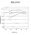
- Fig. 13(C) is a graph representing the birefrigence in the above-described information recording disc.
- a vertical axis in Fig. 13(C) denotes the birefrigence in a unit of nm when a laser beam is reciprocated and a horizontal axis therein denotes a distance in a unit of mm from the center of the information recording disc m in a radial direction.
- a curve A represents the birefrigence of the disc main body a before the hub d is fixed to the substrate by means of the thermal expansion molding
- a curve B represents the birefrigence thereof after the hub d is fixed to the disc main body by means of the thermal expansion molding at an ambient temperature of 20°C
- a curve C represents the birefrigence of the disc main body a when the hub is fixed to the disc main body by means of the thermal expansion molding and thereafter the ambient temperature is increased to 50° C , respectively.
- 13(C) includes: the substrate made of the polycarbonate resin having the thickness of 1.2 mm and outer diameter of 130 mm; the hub made of the polycarbonate resin having the outer diameter of 32 mm and the thickness of 2 mm; and the magnetic circular plate made of a magnetic stainless SUS 430 having the thickness of 0.5 mm and which is press punched.
- a direction of minus sign (-) denotes a direction of the birefrigence generated due to the radial directional stress.
- an object of the present invention to provide an optical recording disc which enables a miniaturization of a disc holding part in an information record/ reproducing apparatus and enables an accurate record/ reproduction of an information on the optical recording disc with a strain generated on the disc remarkably reduced.
- an optical recording disc on which information is optically recorded or reproduced comprising: (a) a disc substrate made of a synthetic resin and having a light transmittance; (b) a hub fixed to a substantially center part of the disc substrate and having a magnetic metal plate; and (c) a groove for absorbing a stress imposed on the optical recording disc and generated due to a difference in thermal expansion rates between the disc substrate made of the synthetic resin and magnetic metal plate, which is located at least at a periphery outside of a part at which the disc substrate and hub are fixed together and is extended on at least either of the disc substrate or hub.
- a magneto-optical disc comprising: (a) a disc substrate made of a synthetic resin material and having a light transmittance; (b) a magnetic metal plate in a ring shape installed on the disc substrate; (c) a hub made of a synthetic resin having the similar characteristic as the disc substrate and fixed to the center part of the disc substrate by means of a thermal expansion molding; and (d) grooves each in a ring shape provided on both peripheral sides inside and outside of a part at which the disc substrate and hub are fixed together and provided on both opposing surfaces of the disc substrate and hub.
- Figs. 4 through 8 show a first preferred embodiment of an optical recording disc according to the present invention which is applicable to a magneto-optical disc.
- the magneto-optical recording disc 1 includes a disc main body 2, a magnetic circular plate 3, and a hub 4.
- the disc main body 2 includes a substrate having a construction in which a synthetic resin, e.g., polycarbonate resin is molded and formed in a circular plate shape, on a flat surface of which an information signal record layer is provided on which a record of information signal is carried out by means of a magneto-optical system utilizing a laser beam and a protective layer made of a synthetic resin is laminated on the record layer.
- a synthetic resin e.g., polycarbonate resin
- the magnetic circular plate 3 is made of a magnetic material, for example, an iron plate on which a chromium plating is carried out or a magnetic stainless plate.
- the reason of carrying out the chromium plating on the iron plate is to provide an antirot property for the magnetic circular plate 3.
- a magnetic stainless SUS 430, etc. Such an original plate made of the magnetic material as described above is formed in the circular shape by means of a press punching.
- a folding part 5 is formed, a peripheral edge of which is bent in a substantially letter Z shape to form a folding part 5.
- a centering hole 6 is provided at a center of the magnetic circular plate 3.
- the hub 4 is formed of a synthetic resin.
- the synthetic resin forming the hub 4 is preferably the same series as that forming the substrate of the disc main body 2.
- the material of the hub 4 may also be of a polycarbonate resin when the polycarbonate resin is used as the material of the disc main body substrate.
- the hub 4 is formed substantially in a ring shape.
- the hub 4 is integrally attached to a peripheral edge of the magnetic circular plate 3 by means of an insert molding. At this time, the folding part 5 formed on the peripheral edge of the magnetic circular plate 3 is burried into the hub 4 so that the magnetic circular plate 3 is securely coupled to the hub 4.
- a couple of grooves 7a, 7b are concentrically formed with respect to a center of the hub 4 and are opposed to an upper surface of the disc main body 2.
- a fixing part 8 is left between the couple of grooves 7a, 7b.
- a rib 9 in a triangular shape of section is formed substantially along a center line of the fixing part 8 of the hub 4. The rib 9 is provided by means of an expansion molding.
- a couple of grooves 10a, 10b are concentrically formed on an upper surface facing the hub 4 with respect to a center of the disc main body 2.
- a fixing part 11 is left on a part between the couple of grooves 10a, lOb.
- the fixing part 11 is formed at a position facing the fixing part 8 of the hub 4 when the center of the hub 4 is overlapped on that of the disc main body 2.
- the rib 9 may be formed on the disc main body 2 in place of the hub 4.
- the hub 4 holding the magnetic circular plate 3 is mounted on the disc main body 2 so that the fixing parts 8 and 11 are overlapped, as shown in Fig. 6.
- a supersonic wave horn 12 is pneumatically pressed against the hub 4.
- a supersonic wave vibration is applied for a predetermined period of time, e.g., for 0.1 through 0.5 seconds through the supersonic wave horn 12.
- a heat generated due to the application of the supersonic wave vibration between the mutual fixing parts 8, 11 of the disc main body 2 and hub 4 causes the rib 9 to be thermally melted so that both fixing parts are thermally molded and fixed together. It should be noted that an extra amount of the melted resin flows into either of the couple of grooves 7a, 7b or 10a, lOb. Consequently, a surface accuracy between the disc main body 2 and hub 4 will not be reduced. In addition, since the transmission of heat when the thermal expansion molding for the fixing parts is carried out is interrupted by the couple of grooves 10a, 10b, the heat will not be transmitted over the surface of the substrate and strain due to the heat will not occur in the substrate.
- the magneto-optical disc generally denoted by 1 is formed.
- Fig. 13(A) shows a graph representing the birefrigence in the magneto-optical disc 1 in the first preferred embodiment. This graph is prepared in the same procedure as that in Fig. 13(C).
- a curve A 1 represents the birefrigence of the disc main body 2 before the hub 4 is thermally fixed to the disc main body 2
- a curve B 1 represents the birefrigence of the disc main body after the hub 4 is thermally fixed to the disc main body 2 at the ambient temperature of 20 0 C
- a curve C 1 represents the birefrigence of the disc main body 2 when the hub 4 is thermally fixed to the disc main body 2 and thereafter the ambient temperature is increased to 50°C.
- the magneto-optical disc 1 used to obtain measured values shown in Fig. 13(A) has the substrate of the disc main body 2 made of the polycarbonate resin molded article and having a thickness of 2 mm and outer diameter of 130 mm, hub 4 made of the polycarbonate resin molded article and having the outer diameter of 32 mm and the thickness of 2 mm, and the magnetic circular plate made of the magnetic stainless, having the thickness of 0.5 mm and which is press punched.
- the change in the bircfrigence becomes extremely small as compared with that shown in Fig. l0(C).
- the maximum value of birefrigence is not more than 40 nm. No practical problem arises.
- Figs. 9 through 11 show a second preferred embodiment of the optical recording disc according to the present invention.
- optical recording disc lA in the second preferred embodiment is different from that in the first preferred embodiment in the structures of the magnetic circular plate and hub.
- the other parts are the same as those in the first preferred embodiment. Therefore, the detailed descriptions of the same elements are omitted here.
- the same reference numerals designate the corresponding elements in the first preferred embodiment.
- numeral 13 denotes the magnetic circular plate.
- the magnetic circular plate 13 is formed of a plate member made of a magnetic material which is press punched. A peripheral edge thereof is provided with a plurality of mounting holes 14, 14, .... Each upper surface of the mounting holes 14, 14, ..., which is an opposite side of the disc main body 2 becomes wider than each bottom surface thereof in a dish hole configuration.
- numeral 15 denotes a centering hole penetrated through a center part of the magnetic circular plate 13.
- the hub 16 is made of the synthetic resin.
- the synthetic resin constituting the hub 16 preferably belongs to the same series as that used for the disc substrate.
- the polycarbonate resin is preferable.
- the hub 16 is circularly formed.
- a shallow recess 17 is formed with an outer periphery left on the surface opposite to the disc main body surface.
- the outer edge part of the magnetic circular plate 13 is fitted into the recess 17.
- a plurality of projections 18, 18, ... are fitted into the mounting holes 14, 14, ... of the magnetic circular plate 13, so that the magnetic circular plate 13 is coupled to the hub 16.
- the magnetic circular plate 13 is coupled to the hub 16 in such a way that an injection molding for the hub 16 may be carried out with the outer edge part of the magnetic circular plate 13 inserted within a molding die.
- the projections 18, 18, ... of the hub 16 are inserted into the mounting holes 14, 14, ... of the magnetic circular plate 13, and tips of the projections 18, 18, ..., are staked. Since in this coupling state the tips of the projections 18, 18, ... of the hub 16 are expanded and raised laterally so as to engage with the dish hole parts of the mounting holes 14, 14, ..., the magnetic circular plate 13 can securely be coupled to the hub 16.
- a circular groove 19 is formed substantially along the center line of the surface 20 opposing the disc main body 2.
- a plurality of fixing parts 21, 21, ... are formed in a rib configuration which are triangles in cross sections so as to align with a circle substantially along the center line. The tip ends of these fixing parts 21, 21, ..., are slightly projected from the above-described surface 20.
- These fixing parts 21, 21, ..., described above serve as the rib provided in the first preferred embodiment.
- the fixing parts 18, 18, ... of the hub 16 which holds the magnetic circular plate 13 described above are coupled to the fixing parts 11, 11, ... by means of a supersonic wave expansion molding. Consequently, the hub 16 is coupled to the disc main body 2 and the magneto-optical disc 1A is formed.
- the information recording disc as the magneto-optical disc lA is completed which has the same effect as that in the first preferred embodiment.
- the cost is accordingly reduced. Since the surface of the turn table f opposing the magnet i can be increased for the diameter of the magnetic circular plate 13, the diameter of the magnetic circular plate 13 can be reduced to achieve the same holding force as compared with that of the second preferred embodiment. Hence, the diameter of the magnetic circular plate 13 can be reduced. The outer diameter of the hub 13 can accordingly be reduced. This makes possible the coupling part between the hub 16 and disc main body 2 nearer to the center of the disc main body. Therefore, an influence of the birefrigence on the record area can accordingly be reduced.
- the hub 16 in the second preferred embodiment can have the same suction and attaching force as that in the first preferred embodiment even if the outer diameter thereof is 25 mm.
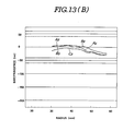
- Fig. 13(B) shows a graph representing the birefrigence with respect to the radial direction of the information recording disc lA of the second preferred embodiment. This graph is prepared in the same manner as that of Fig. l3(C).
- a curve A 2 represents the birefrigence of the disc main body before the hub 16 is thermally melted and fixed to the disc main body 2.
- a curve B 2 represents the birefrigence of the disc main body 2 after the hub 16 is thermally melted and fixed to the disc main body at the ambient temperature of 20 0 C .
- a curve C 2 represents the birefrigence when the hub 16 is thermally melted and fixed to the disc main body and thereafter the ambient temperature is increased to 50° C .
- the information recording disc used for the birefrigence measurement whose result is shown in Fig. 13(B) has the same construction as those used in the birefrigence measurements carried out with reference to Figs. 13(A) and 13(C).
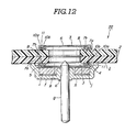
- Fig. 12 shows a rough sketch of a modification of the optical recording disc according to the present invention.
- the modification shown in Fig. 12 is such that two pieces of information recording discs are adhered back to back so that a memory capacity thereof can be doubled.
- the two optical recording discs may be those in the first preferred embodiment or may be those in the second preferred embodiment.
- the optical recording disc according to the present invention can reduce the size of the information record/reproduction apparatus particularly a disc holding part.
- the couple of grooves are provided on least one of the disc main body and hub so that the stress imposed on the disc main body generated due to the difference in the thermal expansion rates between the disc main body and magnetic metal plate is almost cancelled-through the couple of grooves. Consequently, a strain generated in the disc main body can be reduced so that an accurate record and reproduction for the optical recording disc can be achieved.
- groove may be formed on each or either of the disc main body or hub. It is also noted that although the couple of grooves are formed in the complete circular configuration in each preferred embodiment, it is sufficient that the groove(s) may be formed so as to correspond to both disc main body and hub.
- each fixing part is triangle in section as shown in the second preferred embodiment
- inclined angles of both or either inner oblique surface of the triangular fixing point or outer oblique surface thereof may be changed so that a position at which the fixing parts are fixed together can be moved toward a more inner periphery or more outer periphery during the supersonic wave expansion molding.
- This movement permits the adjustment of the stress after the thermal expansion molding is carried out.
- the inclined angle of the inner peripheral side oblique surface becomes larger and that of the outer peripheral side oblique surface becomes smaller, it becomes possible to impose a slight stress on a direction toward which the hub depresses the disc main body substrate outwardly after the thermal expansion molding is carried out. This makes possible the adjustment of the tensile stress generated on the hub and imposed on the disc substrate due to the increase in the ambient temperature.
Landscapes
- Engineering & Computer Science (AREA)
- Mechanical Engineering (AREA)
- Physics & Mathematics (AREA)
- Thermal Sciences (AREA)
- Manufacturing & Machinery (AREA)
- Optical Record Carriers And Manufacture Thereof (AREA)
Abstract
Description
- The present invention relates to an optical recording disc on which an information is optically recorded and/or reproduced.
- The present invention relates particularly to an optical recording disc which can reduce a size of an optical recording/reproducing apparatus using the optical recording disc and can provide a more accurate information recording and reproduction with a strain generated in a disc main body extremely reduced.
- In an information recording disc drive apparatus which carries out a record/reproduction of information with an information recording disc such as a random access type optical disc or a magneto-optical disc, a turn table is usually rotated at an extremely high speed. Therefore, a slip between the turn table and information recording disc will occur in such a case that the information recording disc is merely mounted on the turn table.
- In order to prevent the occurrence of slip, a transferable chuck member is installed which grasps the information recording disc with the turn table when it is moved in a direction of the rotation axle of the turn table so that the information recording disc is firmly grasped.
- However, if the transferable chuck member is installed, a space for a movement stroke of the transferable chuck member must be provided in a thickness direction of the information recording disc drive apparatus. Therefore, the information recording disc drive apparatus cannot sufficiently be miniaturized.
- In order to prevent the occurrence of slip and reduce a size of the information recording disc drive apparatus, such an information recording disc drive apparatus has been proposed that a magnetic circular plate is fixed on the information recording disc and the magnetic circular plate is magnetically attracted to the turn table to hold the information recording disc.
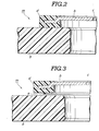
- Figs. 1 through 3 show a turn table for the information recording disc having the construction described above.
- An information recording disc generally denoted by m comprises a disc main body a including a substrate formed of a thermoplastic synthetic resin on which a predetermined record layer and its protective layer are formed. The information recording disc is, for example, an optical disc.
- Located below the information recording disc main body a is a magnetic circular plate b having a centering hole c penetrated therethrough at a center part of the magnetic circular plate b. The magnetic circular plate b is made of a magnetic material and is formed in a circular shape. A hub d is integrally formed with the magnetic circular plate b along an outer peripheral edge thereof. The hub d is circular and is made of a thermoplastic synthetic resin, preferably of the same material as the information recording disc main body a or the same series material. An expansion molding rib e is projected on an upper surface of the hub d.
- The hub d is fixed to a lower surface of the information recording disc main body a by means of a supersonic wave expansion molding so that the magnetic circular plate b is fixed to a lower surface of the information recording disc main body a via the hub d. It is noted that the centering hole c formed so as to penetrate through the magnetic circular plate b is positioned so as to match with the center of the information recording disc main body a.
- A turn table generally denoted by f includes: a drive shaft g; a thick main body part h fixed around an upper end of the drive shaft g; and a magnet fixed to the thick main body part h.
- The turn table f is rotatable by means of a suitable drive mechanism and an upper end thereof is formed in a rounded circular truncated cone shape. In addition, a circular recess j is formed on an upper surface of the turn table main body part h. A circular yoke plate k and circular magnet i are housed in this order and fixed to the circular recess j. Furthermore, a disc receiving surface / is formed at an outside of the recess j and has an inner diameter larger than an outer diameter of the hub d.
- When the information recording disc m is mounted on the turn table f, the magnetic circular plate b attached to the information recording disc m is attracted to the magnet i of the turn table f, so that the upper end of the drive shaft g becomes engaged with the centering hole c provided through the magnetic circular plate b and a lower surface at the outside of the hub d of the information recording disc m is mounted on the disc receiving surface /.
- Hence, the centering of the information recording disc m is carried out when the upper end of the drive shaft g is engaged with the centering hole c of the magnetic circular plate. In addition, a record/reproduction positioning of the information recording disc is carried out by receiving the lower surface at the outside of the hub d of the information recording disc m.
- Since in the turn table f described above, such a member as the transferable chuck member described above which grasps the information recording disc when it is moved in the thickness direction of the information recording disc in order to securely hold the information recording disc main body a is not required, the size of the information recording disc drive apparatus, especially, the size thereof in its thickness direction can accordingly be reduced.
- However, such a problem arises that a strain will occur in the substrate of the information recording disc m described above so that an inaccurate record/read of information will result.
- That is to say, since the hub d which holds the magnetic circular plate b is fixed to the disc main body a by means of the thermal expansion molding, a stress is imposed on the substrate of the disc main body a and causes the generation of stress on the substrate. In addition, in an information record/playback apparatus using such an information recording disc, a temperature within the apparatus reaches as high as 50°C or more during operation so that a temperature difference from a normal temperature becomes 200C or more. Consequently, a stress in a tensile direction (tensile stress) is imposed on the center part of the substrate of the disc main body due to the difference in thermal expansion rates between the substrate of the information recording disc and magnetic circular plate. On the other hand, a stress in a compressive direction (compressive stress) is imposed on a part outside of a part of the disc main body at which the hub d is fixed to the substrate of the disc main body by means of an expansion molding.
- Furthermore, if the information recording disc m is a magneto-optical disc, the above-described stresses cause a birefrigence and therefore reduces a property of the optical recording disc. Particularly, since a minute rotation of a polarized surface of light is read as a signal in a case of a magneto-optical disc recording system, the birefrigence makes the signal quality remarkably deteriorated. In addition, since a light elastic modulus of a polycarbonate resin is large in a case when the polycarbonate resin is used as the material of the disc substrate, the increase rate in the birefrigence is large due to the temperature difference described above as compared with an acrylic resin or glass which is used as the material of the substrate of the disc main body. Specifically, the increase rate of the birefrigence value is 40 nm or more. Consequently, it is impractical.
- Fig. 13(C) is a graph representing the birefrigence in the above-described information recording disc. A vertical axis in Fig. 13(C) denotes the birefrigence in a unit of nm when a laser beam is reciprocated and a horizontal axis therein denotes a distance in a unit of mm from the center of the information recording disc m in a radial direction. A curve A represents the birefrigence of the disc main body a before the hub d is fixed to the substrate by means of the thermal expansion molding, a curve B represents the birefrigence thereof after the hub d is fixed to the disc main body by means of the thermal expansion molding at an ambient temperature of 20°C, and a curve C represents the birefrigence of the disc main body a when the hub is fixed to the disc main body by means of the thermal expansion molding and thereafter the ambient temperature is increased to 50°C, respectively. It is noted that the information recording disc used to obtain measured values shown in Fig. 13(C) includes: the substrate made of the polycarbonate resin having the thickness of 1.2 mm and outer diameter of 130 mm; the hub made of the polycarbonate resin having the outer diameter of 32 mm and the thickness of 2 mm; and the magnetic circular plate made of a magnetic stainless SUS 430 having the thickness of 0.5 mm and which is press punched. In addition, in Fig. 13(C) a direction of minus sign (-) denotes a direction of the birefrigence generated due to the radial directional stress.
- As appreciated from Fig. 13(0, the birefrigence is changed about 100 nm from the curve A to the curve B at a
position 30 mm away in the radial direction from the center of the most inner periphery of a record area of the information recording disc. These measurement results show that the information recording disc drive apparatus having the turn table and the information recording disc described above cannot almost be reduced in a practical use. - With the above-described problem in mind, it is an object of the present invention to provide an optical recording disc which enables a miniaturization of a disc holding part in an information record/ reproducing apparatus and enables an accurate record/ reproduction of an information on the optical recording disc with a strain generated on the disc remarkably reduced.
- The above-described object can be achieved by providing an optical recording disc on which information is optically recorded or reproduced, the optical recording disc comprising: (a) a disc substrate made of a synthetic resin and having a light transmittance; (b) a hub fixed to a substantially center part of the disc substrate and having a magnetic metal plate; and (c) a groove for absorbing a stress imposed on the optical recording disc and generated due to a difference in thermal expansion rates between the disc substrate made of the synthetic resin and magnetic metal plate, which is located at least at a periphery outside of a part at which the disc substrate and hub are fixed together and is extended on at least either of the disc substrate or hub.
- The above-described object can be achieved by providing a magneto-optical disc, comprising: (a) a disc substrate made of a synthetic resin material and having a light transmittance; (b) a magnetic metal plate in a ring shape installed on the disc substrate; (c) a hub made of a synthetic resin having the similar characteristic as the disc substrate and fixed to the center part of the disc substrate by means of a thermal expansion molding; and (d) grooves each in a ring shape provided on both peripheral sides inside and outside of a part at which the disc substrate and hub are fixed together and provided on both opposing surfaces of the disc substrate and hub.
-
- Fig. 1 is a cross sectional view of a previously proposed turn table on which an information recording disc is mounted.
- Fig. 2 is an enlarged sectional view of an essential part of the turn table shown in Fig. 1.
- Fig. 3 is a further enlarged sectional view of the essential part shown in Fig. 2.
- Fig. 4 is an enlarged cross sectional view of an essential part in a first preferred embodiment of an optical recording disc according to the present invention.
- Fig. 5 is a further enlarged cross sectional view of the essential part shown in Fig. 4.
- Fig. 6 is a perspective view of the optical recording disc shown in Figs. 4 and 5.
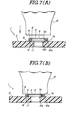
- Figs. 7(A) and 7(B) are cross sectional views for explaining a sequence in which a hub holding a magnetic metal plate is fixed to a disc main body by means of a thermal expansion molding.
- Fig. 8 is an enlarged cross sectional view of the optical recording disc which is mounted on the turn table.
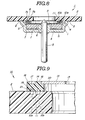
- Fig. 9 is an enlarged cross sectional view of the optical recording disc in a second preferred embodiment according to the present invention.
- Fig. 10 is a longitudinally sectioned view of a hub holding a magnetic metal plate in the second preferred embodiment shown in Fig. 9.
- Fig. 11 is a side view of the optical recording disc and hub shown in Figs. 9 and 10.
- Fig. 12 is a rough cross sectional view of a modification of the optical recording disc.
- Figs. 13(A) through 13(C) are characteristic graphs representing birefrigence with respect to each position of the optical recording discs in their radial directions.
- Reference will hereinafter be made to the drawings in order to facilitate understanding the present invention. The previously proposed optical recording disc has been described with reference to Figs. 1 through 3 and Fig. 13(C).
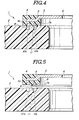
- Figs. 4 through 8 show a first preferred embodiment of an optical recording disc according to the present invention which is applicable to a magneto-optical disc. The magneto-optical recording disc 1 includes a disc
main body 2, a magneticcircular plate 3, and ahub 4. - The disc
main body 2 includes a substrate having a construction in which a synthetic resin, e.g., polycarbonate resin is molded and formed in a circular plate shape, on a flat surface of which an information signal record layer is provided on which a record of information signal is carried out by means of a magneto-optical system utilizing a laser beam and a protective layer made of a synthetic resin is laminated on the record layer. - The magnetic
circular plate 3 is made of a magnetic material, for example, an iron plate on which a chromium plating is carried out or a magnetic stainless plate. The reason of carrying out the chromium plating on the iron plate is to provide an antirot property for the magneticcircular plate 3. In a case when the stainless steel plate is used, it is preferable to use a magnetic stainless SUS 430, etc.. Such an original plate made of the magnetic material as described above is formed in the circular shape by means of a press punching. At the same time, afolding part 5 is formed, a peripheral edge of which is bent in a substantially letter Z shape to form afolding part 5. In Figs. 4 and 5, a centeringhole 6 is provided at a center of the magneticcircular plate 3. - The
hub 4 is formed of a synthetic resin. The synthetic resin forming thehub 4 is preferably the same series as that forming the substrate of the discmain body 2. For example, the material of thehub 4 may also be of a polycarbonate resin when the polycarbonate resin is used as the material of the disc main body substrate. Thehub 4 is formed substantially in a ring shape. Thehub 4 is integrally attached to a peripheral edge of the magneticcircular plate 3 by means of an insert molding. At this time, thefolding part 5 formed on the peripheral edge of the magneticcircular plate 3 is burried into thehub 4 so that the magneticcircular plate 3 is securely coupled to thehub 4. - A couple of
grooves hub 4 and are opposed to an upper surface of the discmain body 2. A fixingpart 8 is left between the couple ofgrooves rib 9 in a triangular shape of section is formed substantially along a center line of the fixingpart 8 of thehub 4. Therib 9 is provided by means of an expansion molding. - It is noted that a couple of
grooves 10a, 10b are concentrically formed on an upper surface facing thehub 4 with respect to a center of the discmain body 2. A fixingpart 11 is left on a part between the couple ofgrooves 10a, lOb. The fixingpart 11 is formed at a position facing the fixingpart 8 of thehub 4 when the center of thehub 4 is overlapped on that of the discmain body 2. It is noted that therib 9 may be formed on the discmain body 2 in place of thehub 4. - The
hub 4 holding the magneticcircular plate 3 is mounted on the discmain body 2 so that the fixingparts supersonic wave horn 12 is pneumatically pressed against thehub 4. A supersonic wave vibration is applied for a predetermined period of time, e.g., for 0.1 through 0.5 seconds through thesupersonic wave horn 12. - A heat generated due to the application of the supersonic wave vibration between the
mutual fixing parts main body 2 andhub 4 causes therib 9 to be thermally melted so that both fixing parts are thermally molded and fixed together. It should be noted that an extra amount of the melted resin flows into either of the couple ofgrooves main body 2 andhub 4 will not be reduced. In addition, since the transmission of heat when the thermal expansion molding for the fixing parts is carried out is interrupted by the couple ofgrooves 10a, 10b, the heat will not be transmitted over the surface of the substrate and strain due to the heat will not occur in the substrate. - In this way, the magneto-optical disc generally denoted by 1 is formed.
- Therefore, when the magneto-optical disc 1 is used, the ambient temperature rises, and a difference in the thermal expansion rate between those of the substrate of the disc
main body 2 and magneticcircular plate 3 exists, the stress generated due to the difference described above is remarkably reduced by elasticity provided for the fixingparts grooves main body 2 is extremely reduced. Fig. 13(A) shows a graph representing the birefrigence in the magneto-optical disc 1 in the first preferred embodiment. This graph is prepared in the same procedure as that in Fig. 13(C). A curve A1 represents the birefrigence of the discmain body 2 before thehub 4 is thermally fixed to the discmain body 2, a curve B1 represents the birefrigence of the disc main body after thehub 4 is thermally fixed to the discmain body 2 at the ambient temperature of 200 C, and a curve C1 represents the birefrigence of the discmain body 2 when thehub 4 is thermally fixed to the discmain body 2 and thereafter the ambient temperature is increased to 50°C. - The magneto-optical disc 1 used to obtain measured values shown in Fig. 13(A) has the substrate of the disc
main body 2 made of the polycarbonate resin molded article and having a thickness of 2 mm and outer diameter of 130 mm,hub 4 made of the polycarbonate resin molded article and having the outer diameter of 32 mm and the thickness of 2 mm, and the magnetic circular plate made of the magnetic stainless, having the thickness of 0.5 mm and which is press punched. As appreciated from Fig. 13(A), the change in the bircfrigence becomes extremely small as compared with that shown in Fig. l0(C). The maximum value of birefrigence is not more than 40 nm. No practical problem arises. - Figs. 9 through 11 show a second preferred embodiment of the optical recording disc according to the present invention.
- The optical recording disc lA in the second preferred embodiment is different from that in the first preferred embodiment in the structures of the magnetic circular plate and hub. The other parts are the same as those in the first preferred embodiment. Therefore, the detailed descriptions of the same elements are omitted here. The same reference numerals designate the corresponding elements in the first preferred embodiment.
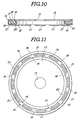
- In Figs. 9 through 11, numeral 13 denotes the magnetic circular plate. The magnetic
circular plate 13 is formed of a plate member made of a magnetic material which is press punched. A peripheral edge thereof is provided with a plurality of mountingholes holes main body 2 becomes wider than each bottom surface thereof in a dish hole configuration. It is noted that numeral 15 denotes a centering hole penetrated through a center part of the magneticcircular plate 13. - The
hub 16 is made of the synthetic resin. The synthetic resin constituting thehub 16 preferably belongs to the same series as that used for the disc substrate. For example, the polycarbonate resin is preferable. - The
hub 16 is circularly formed. Ashallow recess 17 is formed with an outer periphery left on the surface opposite to the disc main body surface. The outer edge part of the magneticcircular plate 13 is fitted into therecess 17. A plurality ofprojections holes circular plate 13, so that the magneticcircular plate 13 is coupled to thehub 16. - The magnetic
circular plate 13 is coupled to thehub 16 in such a way that an injection molding for thehub 16 may be carried out with the outer edge part of the magneticcircular plate 13 inserted within a molding die. After molding of thehub 16 only, theprojections hub 16 are inserted into the mountingholes circular plate 13, and tips of theprojections projections hub 16 are expanded and raised laterally so as to engage with the dish hole parts of the mountingholes circular plate 13 can securely be coupled to thehub 16. - A
circular groove 19 is formed substantially along the center line of thesurface 20 opposing the discmain body 2. A plurality of fixingparts parts surface 20. These fixingparts - The fixing
parts hub 16 which holds the magneticcircular plate 13 described above are coupled to the fixingparts hub 16 is coupled to the discmain body 2 and the magneto-optical disc 1A is formed. The information recording disc as the magneto-optical disc lA is completed which has the same effect as that in the first preferred embodiment. - It should be noted that since a drawing is not required on its outer edge portion of the magnetic
circular plate 13 in the second preferred embodiment, the cost is accordingly reduced. Since the surface of the turn table f opposing the magnet i can be increased for the diameter of the magneticcircular plate 13, the diameter of the magneticcircular plate 13 can be reduced to achieve the same holding force as compared with that of the second preferred embodiment. Hence, the diameter of the magneticcircular plate 13 can be reduced. The outer diameter of thehub 13 can accordingly be reduced. This makes possible the coupling part between thehub 16 and discmain body 2 nearer to the center of the disc main body. Therefore, an influence of the birefrigence on the record area can accordingly be reduced. - For example, in a case when the outer diameter of the
hub 16 in the first preferred embodiment is 32 mm, thehub 16 in the second preferred embodiment can have the same suction and attaching force as that in the first preferred embodiment even if the outer diameter thereof is 25 mm. - Fig. 13(B) shows a graph representing the birefrigence with respect to the radial direction of the information recording disc lA of the second preferred embodiment. This graph is prepared in the same manner as that of Fig. l3(C). A curve A2 represents the birefrigence of the disc main body before the
hub 16 is thermally melted and fixed to the discmain body 2. A curve B2 represents the birefrigence of the discmain body 2 after thehub 16 is thermally melted and fixed to the disc main body at the ambient temperature of 200 C. A curve C2 represents the birefrigence when thehub 16 is thermally melted and fixed to the disc main body and thereafter the ambient temperature is increased to 50°C. It should be noted that the information recording disc used for the birefrigence measurement whose result is shown in Fig. 13(B) has the same construction as those used in the birefrigence measurements carried out with reference to Figs. 13(A) and 13(C). - As appreciated from Fig. 13(C) the change rate of birefrigence is remarkably reduced as compared with that shown in Fig. 13(C). Furthermore, it is smaller than that in the first preferred embodiment.
- Fig. 12 shows a rough sketch of a modification of the optical recording disc according to the present invention. The modification shown in Fig. 12 is such that two pieces of information recording discs are adhered back to back so that a memory capacity thereof can be doubled. It is noted that the two optical recording discs may be those in the first preferred embodiment or may be those in the second preferred embodiment. As described hereinabove, the optical recording disc according to the present invention can reduce the size of the information record/reproduction apparatus particularly a disc holding part. In addition, the couple of grooves are provided on least one of the disc main body and hub so that the stress imposed on the disc main body generated due to the difference in the thermal expansion rates between the disc main body and magnetic metal plate is almost cancelled-through the couple of grooves. Consequently, a strain generated in the disc main body can be reduced so that an accurate record and reproduction for the optical recording disc can be achieved.
- It is noted that although in each preferred embodiment the groove may be formed on each or either of the disc main body or hub. It is also noted that although the couple of grooves are formed in the complete circular configuration in each preferred embodiment, it is sufficient that the groove(s) may be formed so as to correspond to both disc main body and hub.
- Although in the case where the shape of each fixing part is triangle in section as shown in the second preferred embodiment, inclined angles of both or either inner oblique surface of the triangular fixing point or outer oblique surface thereof may be changed so that a position at which the fixing parts are fixed together can be moved toward a more inner periphery or more outer periphery during the supersonic wave expansion molding. This movement permits the adjustment of the stress after the thermal expansion molding is carried out. For example, if the inclined angle of the inner peripheral side oblique surface becomes larger and that of the outer peripheral side oblique surface becomes smaller, it becomes possible to impose a slight stress on a direction toward which the hub depresses the disc main body substrate outwardly after the thermal expansion molding is carried out. This makes possible the adjustment of the tensile stress generated on the hub and imposed on the disc substrate due to the increase in the ambient temperature.
- It will fully be understood by those skilled in the art that the foregoing description is made in terms of the preferred embodiments and various modifications may be made without departing from the scope of the present invention which is to be defined by the appended claims.
Claims (43)
Applications Claiming Priority (2)
| Application Number | Priority Date | Filing Date | Title |
|---|---|---|---|
| JP35890/86 | 1986-02-20 | ||
| JP61035890A JPS62192945A (en) | 1986-02-20 | 1986-02-20 | Information disk |
Publications (3)
| Publication Number | Publication Date |
|---|---|
| EP0233644A2 true EP0233644A2 (en) | 1987-08-26 |
| EP0233644A3 EP0233644A3 (en) | 1990-05-30 |
| EP0233644B1 EP0233644B1 (en) | 1992-04-22 |
Family
ID=12454614
Family Applications (1)
| Application Number | Title | Priority Date | Filing Date |
|---|---|---|---|
| EP87102307A Expired - Lifetime EP0233644B1 (en) | 1986-02-20 | 1987-02-18 | An optical recording disc |
Country Status (6)
| Country | Link |
|---|---|
| US (1) | US4785444A (en) |
| EP (1) | EP0233644B1 (en) |
| JP (1) | JPS62192945A (en) |
| KR (1) | KR950008951B1 (en) |
| CA (1) | CA1276722C (en) |
| DE (1) | DE3778391D1 (en) |
Cited By (17)
| Publication number | Priority date | Publication date | Assignee | Title |
|---|---|---|---|---|
| DE3734670A1 (en) * | 1986-10-13 | 1988-06-16 | Pioneer Electronic Corp | METHOD FOR PRODUCING A RECORDING PLATE FOR OPTICAL INFORMATION |
| EP0270182A3 (en) * | 1986-12-01 | 1988-07-27 | Optical Storage International Holland | Information carrier |
| EP0284162A1 (en) * | 1987-03-26 | 1988-09-28 | Optical Storage International Holland | Turntable device for an information disc |
| DE3808180A1 (en) * | 1987-03-16 | 1988-11-03 | Pioneer Electronic Corp | RECORDING PLATE FOR OPTICAL INFORMATION |
| EP0269411A3 (en) * | 1986-11-28 | 1989-01-04 | Kabushiki Kaisha Toshiba | Information memory medium |
| EP0266747A3 (en) * | 1986-11-05 | 1989-04-05 | Kabushiki Kaisha Toshiba | Information memory medium |
| EP0283921A3 (en) * | 1987-03-20 | 1989-11-15 | Sony Corporation | Disk drive device |
| EP0314010A3 (en) * | 1987-10-27 | 1990-01-31 | Seiko Epson Corporation | Information recording disk |
| EP0301866A3 (en) * | 1987-07-31 | 1990-02-28 | Mitsui Petrochemical Industries, Ltd. | Process for producing magnetic hub |
| EP0516329A3 (en) * | 1991-05-29 | 1992-12-16 | Sony Corporation | Optical disc and method for producing the optical disc |
| EP0277235B1 (en) * | 1986-07-22 | 1992-12-30 | Mitsubishi Denki Kabushiki Kaisha | Optical disc |
| EP0521654A3 (en) * | 1991-06-29 | 1993-06-09 | Sony Corporation | Disc for recording information signals |
| EP0557147A1 (en) * | 1992-01-31 | 1993-08-25 | Sony Corporation | Mold device for fabricating disc susbstrate and disc substrate fabricated by this mold device |
| US5265086A (en) * | 1987-10-27 | 1993-11-23 | Seiko Epson Corporation | Information recording disk |
| EP0762418A3 (en) * | 1995-08-15 | 1997-07-16 | Sharp Kk | Disk-use hub, disk cartridge, and disk driving device |
| WO1998006096A1 (en) * | 1996-08-07 | 1998-02-12 | Imation Corp. | Plain carbon steel hub for data storage device |
| EP1072391A3 (en) * | 1999-07-27 | 2001-02-14 | Emhart Inc. | Plastic clip bonding method and plastic clip |
Families Citing this family (23)
| Publication number | Priority date | Publication date | Assignee | Title |
|---|---|---|---|---|
| US4897134A (en) * | 1986-01-27 | 1990-01-30 | Minnesota Mining And Manufacturing Company | Ultrasonic welding hubs to magnetic recording diskettes |
| JPH07101521B2 (en) * | 1986-10-30 | 1995-11-01 | 旭化成工業株式会社 | Optical information recording disc |
| JP2647370B2 (en) * | 1986-11-27 | 1997-08-27 | 日立マクセル株式会社 | Optical information recording disk for magnetic clamp |
| US5265087A (en) * | 1986-11-28 | 1993-11-23 | Kabushiki Kaisha Toshiba | Information medium with improved temperature characteristics |
| JPH01112545A (en) * | 1987-10-23 | 1989-05-01 | Fuji Photo Film Co Ltd | Manufacture of information recording medium |
| US5010435A (en) * | 1987-12-03 | 1991-04-23 | Tdk Corporation | Hub for a disk type recording medium |
| JPH0229981A (en) * | 1988-07-18 | 1990-01-31 | Fuji Photo Film Co Ltd | Manufacture of information recording medium |
| JPH02189776A (en) * | 1989-01-18 | 1990-07-25 | Kyocera Corp | Optical disk and its manufacture |
| JPH0454069U (en) * | 1990-09-04 | 1992-05-08 | ||
| JP3032587B2 (en) * | 1990-12-28 | 2000-04-17 | ティーディーケイ株式会社 | Optical disc manufacturing method |
| JP3498099B2 (en) * | 1993-04-27 | 2004-02-16 | ソニー株式会社 | Recording media disk |
| JP2952468B2 (en) * | 1995-10-05 | 1999-09-27 | 株式会社ニフコ | Hub mounting structure for information disks |
| JP2611753B2 (en) * | 1995-12-18 | 1997-05-21 | 株式会社日立製作所 | disk |
| KR100268492B1 (en) * | 1996-01-11 | 2000-10-16 | 윤종용 | Hard disk drive media |
| JPH1040578A (en) * | 1996-07-23 | 1998-02-13 | Mitsubishi Chem Corp | Board for disk |
| US6002663A (en) | 1997-04-17 | 1999-12-14 | Imation Corp. | Hubless optical disc having low radial runout and method of manufacture |
| US6154441A (en) * | 1997-04-17 | 2000-11-28 | Imation Corp. | Method for centering a hub in an optical disc, and an optical storage system using such disc |
| GB9803604D0 (en) * | 1998-02-21 | 1998-04-15 | Merit Abrasives Europ Limited | Surface treatment |
| US7027385B1 (en) * | 1998-11-06 | 2006-04-11 | Hitachi Maxell, Ltd. | Optical disk, disk substrate, and drive |
| US7448055B2 (en) * | 2004-05-28 | 2008-11-04 | Hitachi Global Storage Technologies Netherlands B.V. | Disk assembly having integral clamp and/or spacer |
| CN100392808C (en) * | 2006-06-23 | 2008-06-04 | 河北工业大学 | Method for removing pollutants on integrated circuit chip surface by electrochemical action |
| US7736568B2 (en) * | 2006-09-19 | 2010-06-15 | Mattel, Inc. | Systems and methods of incorporating preformed items into a molded article |
| EP1923873A1 (en) * | 2006-11-15 | 2008-05-21 | ODS Technology GmbH | EcoDisc |
Family Cites Families (10)
| Publication number | Priority date | Publication date | Assignee | Title |
|---|---|---|---|---|
| JPS58130451A (en) * | 1982-01-29 | 1983-08-03 | Toshiba Corp | Information storage medium |
| JPS5950034U (en) * | 1982-09-21 | 1984-04-03 | ソニー株式会社 | Information record sheet |
| NL8300479A (en) * | 1983-02-09 | 1984-09-03 | Philips Nv | OPTICALLY READABLE PLATE. |
| JPS6035385A (en) * | 1983-08-03 | 1985-02-23 | Hitachi Maxell Ltd | Disk cartridge |
| JPH0636253B2 (en) * | 1983-08-18 | 1994-05-11 | シャープ株式会社 | Optical memory disc |
| JPS60163547U (en) * | 1984-04-09 | 1985-10-30 | ティアック株式会社 | magnetic disk rotation device |
| JPH079257Y2 (en) * | 1984-06-22 | 1995-03-06 | 富士写真フイルム株式会社 | Magnetic disk cartridge |
| FR2567674B1 (en) * | 1984-07-10 | 1987-01-16 | Thomson Alcatel Gigadisc | PROTECTED OPTICAL DISC WITH WELDED ELEMENTS |
| JPH0422431Y2 (en) * | 1985-01-24 | 1992-05-22 | ||
| KR900004661B1 (en) * | 1986-01-20 | 1990-07-02 | 가부시키가이샤 도시바 | Information processing device |
-
1986
- 1986-02-20 JP JP61035890A patent/JPS62192945A/en active Pending
-
1987
- 1987-02-13 CA CA000529674A patent/CA1276722C/en not_active Expired - Lifetime
- 1987-02-18 EP EP87102307A patent/EP0233644B1/en not_active Expired - Lifetime
- 1987-02-18 DE DE8787102307T patent/DE3778391D1/en not_active Expired - Lifetime
- 1987-02-19 KR KR1019870001370A patent/KR950008951B1/en not_active Expired - Lifetime
- 1987-02-20 US US07/016,784 patent/US4785444A/en not_active Expired - Lifetime
Cited By (28)
| Publication number | Priority date | Publication date | Assignee | Title |
|---|---|---|---|---|
| EP0277235B1 (en) * | 1986-07-22 | 1992-12-30 | Mitsubishi Denki Kabushiki Kaisha | Optical disc |
| US4871404A (en) * | 1986-10-13 | 1989-10-03 | Pioneer Electronic Corporation | Method for producing an optical information recording disk |
| DE3734670A1 (en) * | 1986-10-13 | 1988-06-16 | Pioneer Electronic Corp | METHOD FOR PRODUCING A RECORDING PLATE FOR OPTICAL INFORMATION |
| EP0266747A3 (en) * | 1986-11-05 | 1989-04-05 | Kabushiki Kaisha Toshiba | Information memory medium |
| EP0269411A3 (en) * | 1986-11-28 | 1989-01-04 | Kabushiki Kaisha Toshiba | Information memory medium |
| EP0270182A3 (en) * | 1986-12-01 | 1988-07-27 | Optical Storage International Holland | Information carrier |
| US4910624A (en) * | 1986-12-01 | 1990-03-20 | U.S. Philips Corporation | Optically readable disk with self centering hub |
| US4903224A (en) * | 1987-03-16 | 1990-02-20 | Pioneer Electronic Corporation | Optical information recording disk |
| DE3808180A1 (en) * | 1987-03-16 | 1988-11-03 | Pioneer Electronic Corp | RECORDING PLATE FOR OPTICAL INFORMATION |
| EP0283921A3 (en) * | 1987-03-20 | 1989-11-15 | Sony Corporation | Disk drive device |
| EP0284162A1 (en) * | 1987-03-26 | 1988-09-28 | Optical Storage International Holland | Turntable device for an information disc |
| US5020207A (en) * | 1987-07-31 | 1991-06-04 | Mitsui Petrochemical Industries, Ltd. | Process for producing magnetic hub |
| EP0301866A3 (en) * | 1987-07-31 | 1990-02-28 | Mitsui Petrochemical Industries, Ltd. | Process for producing magnetic hub |
| US5265086A (en) * | 1987-10-27 | 1993-11-23 | Seiko Epson Corporation | Information recording disk |
| EP0314010A3 (en) * | 1987-10-27 | 1990-01-31 | Seiko Epson Corporation | Information recording disk |
| US5504735A (en) * | 1987-10-27 | 1996-04-02 | Seiko Epson Corporation | Information recording disk having a stepped central recess and hub configuration |
| EP0516329A3 (en) * | 1991-05-29 | 1992-12-16 | Sony Corporation | Optical disc and method for producing the optical disc |
| US5323381A (en) * | 1991-06-29 | 1994-06-21 | Sony Corporation | Disc for recording information signals |
| EP0521654A3 (en) * | 1991-06-29 | 1993-06-09 | Sony Corporation | Disc for recording information signals |
| EP0557147A1 (en) * | 1992-01-31 | 1993-08-25 | Sony Corporation | Mold device for fabricating disc susbstrate and disc substrate fabricated by this mold device |
| US5427520A (en) * | 1992-01-31 | 1995-06-27 | Sony Corporation | Mold device for fabricating disc substrate |
| EP0762418A3 (en) * | 1995-08-15 | 1997-07-16 | Sharp Kk | Disk-use hub, disk cartridge, and disk driving device |
| WO1998006096A1 (en) * | 1996-08-07 | 1998-02-12 | Imation Corp. | Plain carbon steel hub for data storage device |
| US5896241A (en) * | 1996-08-07 | 1999-04-20 | Imation Corp. | Plain carbon steel hub for data storage device |
| US6292996B1 (en) | 1996-08-07 | 2001-09-25 | Imation Corp. | Method of making a plain carbon steel hub for data storage device |
| DE19781906C2 (en) * | 1996-08-07 | 2002-06-27 | Imation Corp | Pure carbon steel hub for a data storage device |
| EP1072391A3 (en) * | 1999-07-27 | 2001-02-14 | Emhart Inc. | Plastic clip bonding method and plastic clip |
| US6703129B1 (en) | 1999-07-27 | 2004-03-09 | Newfrey Llc | Plastic clip bonding method and plastic clip |
Also Published As
| Publication number | Publication date |
|---|---|
| US4785444A (en) | 1988-11-15 |
| KR950008951B1 (en) | 1995-08-09 |
| EP0233644B1 (en) | 1992-04-22 |
| CA1276722C (en) | 1990-11-20 |
| EP0233644A3 (en) | 1990-05-30 |
| JPS62192945A (en) | 1987-08-24 |
| DE3778391D1 (en) | 1992-05-27 |
| KR870008291A (en) | 1987-09-25 |
Similar Documents
| Publication | Publication Date | Title |
|---|---|---|
| US4785444A (en) | Optical recording disc | |
| US5859834A (en) | Optical disc with magnetic member in a recessed portion thereof and method for producing said optical disc | |
| AU666307B2 (en) | Disc for recording information signals | |
| US4926410A (en) | Disk | |
| EP0314010B1 (en) | Information recording disk | |
| AU648383B2 (en) | Disc for recording information signals and disc chucking device | |
| US5180595A (en) | Metal mold for resin substrate for an optical recording medium | |
| US6347070B1 (en) | Plastic clamp with hub and platter for use in disc drive | |
| US4733388A (en) | Information recording disc | |
| US7057817B2 (en) | Optical lens device and production method thereof | |
| US4983439A (en) | Method of manufacturing a recording medium and recording medium | |
| JPH0766574B2 (en) | Information disk | |
| JP2674067B2 (en) | optical disk | |
| JPH02281487A (en) | Substrate for information recording medium and information recording medium using the same | |
| JPS6117551Y2 (en) | ||
| JPH07225981A (en) | Magnetic head for magneto-optical recording | |
| JPH0531721Y2 (en) | ||
| JPH10112153A (en) | Disc-shaped recording medium | |
| JP2959208B2 (en) | Information signal recording disk | |
| JPS63193391A (en) | Disk device | |
| JPH0516692Y2 (en) | ||
| JPH0366080A (en) | Mount part of optical disk | |
| JPS60164975A (en) | Disk cartridge | |
| JPH0244543A (en) | Optical information recording disk | |
| JPH04283432A (en) | recording disc |
Legal Events
| Date | Code | Title | Description |
|---|---|---|---|
| PUAI | Public reference made under article 153(3) epc to a published international application that has entered the european phase |
Free format text: ORIGINAL CODE: 0009012 |
|
| AK | Designated contracting states |
Kind code of ref document: A2 Designated state(s): DE FR GB NL |
|
| PUAL | Search report despatched |
Free format text: ORIGINAL CODE: 0009013 |
|
| AK | Designated contracting states |
Kind code of ref document: A3 Designated state(s): DE FR GB NL |
|
| 17P | Request for examination filed |
Effective date: 19901030 |
|
| 17Q | First examination report despatched |
Effective date: 19910118 |
|
| GRAA | (expected) grant |
Free format text: ORIGINAL CODE: 0009210 |
|
| AK | Designated contracting states |
Kind code of ref document: B1 Designated state(s): DE FR GB NL |
|
| REF | Corresponds to: |
Ref document number: 3778391 Country of ref document: DE Date of ref document: 19920527 |
|
| ET | Fr: translation filed | ||
| PLBI | Opposition filed |
Free format text: ORIGINAL CODE: 0009260 |
|
| 26 | Opposition filed |
Opponent name: CANON, INC. Effective date: 19930120 |
|
| NLR1 | Nl: opposition has been filed with the epo |
Opponent name: CANON, INC. |
|
| PLAB | Opposition data, opponent's data or that of the opponent's representative modified |
Free format text: ORIGINAL CODE: 0009299OPPO |
|
| PLBQ | Unpublished change to opponent data |
Free format text: ORIGINAL CODE: EPIDOS OPPO |
|
| R26 | Opposition filed (corrected) |
Opponent name: CANON, INC. Effective date: 19930120 |
|
| NLR1 | Nl: opposition has been filed with the epo |
Opponent name: CANON, INC. |
|
| PLBO | Opposition rejected |
Free format text: ORIGINAL CODE: EPIDOS REJO |
|
| PLBN | Opposition rejected |
Free format text: ORIGINAL CODE: 0009273 |
|
| STAA | Information on the status of an ep patent application or granted ep patent |
Free format text: STATUS: OPPOSITION REJECTED |
|
| 27O | Opposition rejected |
Effective date: 19970127 |
|
| NLR2 | Nl: decision of opposition | ||
| REG | Reference to a national code |
Ref country code: GB Ref legal event code: IF02 |
|
| PGFP | Annual fee paid to national office [announced via postgrant information from national office to epo] |
Ref country code: FR Payment date: 20020212 Year of fee payment: 16 |
|
| PGFP | Annual fee paid to national office [announced via postgrant information from national office to epo] |
Ref country code: GB Payment date: 20020220 Year of fee payment: 16 |
|
| PGFP | Annual fee paid to national office [announced via postgrant information from national office to epo] |
Ref country code: NL Payment date: 20020228 Year of fee payment: 16 |
|
| PGFP | Annual fee paid to national office [announced via postgrant information from national office to epo] |
Ref country code: DE Payment date: 20020306 Year of fee payment: 16 |
|
| PG25 | Lapsed in a contracting state [announced via postgrant information from national office to epo] |
Ref country code: GB Free format text: LAPSE BECAUSE OF NON-PAYMENT OF DUE FEES Effective date: 20030218 |
|
| PG25 | Lapsed in a contracting state [announced via postgrant information from national office to epo] |
Ref country code: NL Free format text: LAPSE BECAUSE OF NON-PAYMENT OF DUE FEES Effective date: 20030901 |
|
| PG25 | Lapsed in a contracting state [announced via postgrant information from national office to epo] |
Ref country code: DE Free format text: LAPSE BECAUSE OF NON-PAYMENT OF DUE FEES Effective date: 20030902 |
|
| GBPC | Gb: european patent ceased through non-payment of renewal fee | ||
| PG25 | Lapsed in a contracting state [announced via postgrant information from national office to epo] |
Ref country code: FR Free format text: LAPSE BECAUSE OF NON-PAYMENT OF DUE FEES Effective date: 20031031 |
|
| NLV4 | Nl: lapsed or anulled due to non-payment of the annual fee |
Effective date: 20030901 |
|
| REG | Reference to a national code |
Ref country code: FR Ref legal event code: ST |