EP0521123B1 - Aerial diversity installation with at least two aerials for the mobile reception of metre and decimetre waves - Google Patents
Aerial diversity installation with at least two aerials for the mobile reception of metre and decimetre waves Download PDFInfo
- Publication number
- EP0521123B1 EP0521123B1 EP92902914A EP92902914A EP0521123B1 EP 0521123 B1 EP0521123 B1 EP 0521123B1 EP 92902914 A EP92902914 A EP 92902914A EP 92902914 A EP92902914 A EP 92902914A EP 0521123 B1 EP0521123 B1 EP 0521123B1
- Authority
- EP
- European Patent Office
- Prior art keywords
- antenna
- signal
- tuner
- diversity system
- signals
- Prior art date
- Legal status (The legal status is an assumption and is not a legal conclusion. Google has not performed a legal analysis and makes no representation as to the accuracy of the status listed.)
- Expired - Lifetime
Links
Images


Classifications
-
- H—ELECTRICITY
- H04—ELECTRIC COMMUNICATION TECHNIQUE
- H04B—TRANSMISSION
- H04B7/00—Radio transmission systems, i.e. using radiation field
- H04B7/02—Diversity systems; Multi-antenna system, i.e. transmission or reception using multiple antennas
- H04B7/04—Diversity systems; Multi-antenna system, i.e. transmission or reception using multiple antennas using two or more spaced independent antennas
- H04B7/08—Diversity systems; Multi-antenna system, i.e. transmission or reception using multiple antennas using two or more spaced independent antennas at the receiving station
- H04B7/0802—Diversity systems; Multi-antenna system, i.e. transmission or reception using multiple antennas using two or more spaced independent antennas at the receiving station using antenna selection
- H04B7/0805—Diversity systems; Multi-antenna system, i.e. transmission or reception using multiple antennas using two or more spaced independent antennas at the receiving station using antenna selection with single receiver and antenna switching
- H04B7/0814—Diversity systems; Multi-antenna system, i.e. transmission or reception using multiple antennas using two or more spaced independent antennas at the receiving station using antenna selection with single receiver and antenna switching based on current reception conditions, e.g. switching to different antenna when signal level is below threshold
-
- H—ELECTRICITY
- H04—ELECTRIC COMMUNICATION TECHNIQUE
- H04B—TRANSMISSION
- H04B7/00—Radio transmission systems, i.e. using radiation field
- H04B7/02—Diversity systems; Multi-antenna system, i.e. transmission or reception using multiple antennas
- H04B7/04—Diversity systems; Multi-antenna system, i.e. transmission or reception using multiple antennas using two or more spaced independent antennas
- H04B7/08—Diversity systems; Multi-antenna system, i.e. transmission or reception using multiple antennas using two or more spaced independent antennas at the receiving station
- H04B7/0837—Diversity systems; Multi-antenna system, i.e. transmission or reception using multiple antennas using two or more spaced independent antennas at the receiving station using pre-detection combining
- H04B7/0842—Weighted combining
Definitions
- the invention relates to an antenna diversity system with at least two antennas for the mobile reception of meter and detimeter waves according to the preamble of claim 1.
- Multipath propagation causes considerable reception interference in mobile radio and television reception, which in the case of audio broadcast reception due to noise and pronounced distortion of the low-frequency signal severely impair the listening pleasure and in the case of television reception through ghosting, image flutter, color fading, loss of synchronization and loss of picture to step. Such reception disturbances affect the reception quality considerably; they should therefore be avoided.
- a diversity processor is supplied with at least two antenna signals, the diversity processor containing a frequency deviation threshold and an amplitude threshold, with each of which the current interference-induced frequency interference pulse pulses or the interference-induced amplitude drops in the intermediate frequency signal, which is supplied to the diversity processor from the receiver, be compared. If the interference exceeds the thresholds, a switchover process is initiated such that another antenna signal or another linear combination derived from the antenna signals is fed to the tuner with the IF part.
- This antenna diversity system includes a diversity processor with N antenna signal inputs and a television receiver, the diversity processor being supplied with the video signal and the horizontal and vertical synchronizing signals.
- the diversity processor contains a time gate which is opened by the horizontal synchronizing pulses during the horizontal blanking time, as a result of which the video signal is switched through for signal quality evaluation.
- An address signal is generated via a control circuit in the event of impending picture interference, in such a way that a new antenna signal or another linear combination derived from the antenna signals is fed to the television receiver via an antenna combiner.
- each of the diversity systems described in the above-mentioned patent applications solves the task of reducing the reception interference caused by multipath propagation in a sound or a television channel.
- this requires separate antennas according to the prior art and thus also separate antenna diversity systems both for television reception and for sound reception.
- the picture interference during mobile reception is avoided, but not the sound interference of the associated television sound.
- this is due to the fact that the television picture is amplitude-modulated in a special way, while the television sound is frequency-modulated and the criteria for determining the picture quality are fundamentally completely different from the criteria for determining a sound disturbance.
- the frequency spacing of 5.5 MHz between image and sound carriers means that with such a large frequency spacing, the reception conditions at the location of a receiving antenna for image and sound carriers are completely different, with the result that, for. B. the image disturbance can be maximal and the sound carrier disturbance can be minimal at the same time.
- the object of the invention is therefore to provide an antenna diversity system for the mobile reception of meter and decimeter waves, which makes it possible with a not too large number of antennas, one and the same set of antennas to supply two or more tuners, one of which each has different reception requirements to be used, it should be ensured that the most favorable diversity reception ratios can be set for each tuner.
- Antenna diversity systems of this type are preferably used to improve television and sound reception in the meter and decimeter wave range in motor vehicles.
- the advantages that can be achieved with the invention consist in the considerable reduction in the number of antennas for antenna diversity systems, the tuners of which are used for very different reception requirements.
- a large number would of antennas in today's compact design of modern motor vehicles can no longer be accommodated on or on the vehicle, apart from the difficulty of the wiring and the enormous costs.
- the antenna diversity system according to the invention has the further advantage in television picture and sound reception that z. B. the oscillator of the picture tuner can also be used for the tone tuner, which in turn can save costs.
- the antenna 1 shows an antenna diversity system according to the invention. It consists of a set of N antennas A 1 to AN, which are fed to the inputs of the antenna distributor 1.
- the outputs of the antenna distributor carry the antenna signals and are fed to the two antenna switches 2a and 2b.
- an output signal from the antenna distributor 1 is selected in each case by means of a control line 3a or 3b and switched through to the tuner 4a or 4b.
- the tuner 4a can, as shown in Fig. 1, z. B. be a television picture tuner.
- the RF signal 7a is converted to an intermediate frequency and demodulated, so that its video signal and possibly other signals can be supplied to a diversity processor as a demodulated signal 8a.
- the diversity processor in a known manner, for. B. over a time gate (see. DE-A-39 26 336), in the horizontal blanking time the current image quality compared with a threshold and, if necessary, the control line 3a set so that the antenna switch 2a is caused to a different output signal of the antenna distributor 1 switch. This ensures that the RF signal available with the best image quality is always switched through to the tuner 4a.
- the tuner 4b in Fig. 1 is tuned to the television sound of the same television channel.
- the frequency-modulated, not yet limited IF signal is fed to the diversity processor 9b.
- the diversity processor In the diversity processor, the interference-related frequency interference peaks and the amplitude drops are compared in a known manner (see DE-A-35 17 247) with thresholds.
- the antenna changeover switch 2b In the event of a sound disturbance, the antenna changeover switch 2b is caused via the control line 3b to switch through a better television sound signal to the tuner 4b.
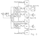
- the sound carriers of which have a spacing of 242 kHz By introducing the stereo sound or the two-channel sound on television, the sound carriers of which have a spacing of 242 kHz, a further tuner 4c is required (see FIG. 6), since at this frequency spacing which is greater than the channel spacing in the case of VHF radio, the received signals at the location of the antennas already show clearly different courses over time, as measurements show. The sound disturbance is also eliminated for the second sound channel according to the described methods.
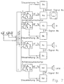
- antenna diversity systems Another advantage with antenna diversity systems according to the invention is that z. B. in luxury sedans in addition to the possibility of television reception with stereo sound, FM radio reception with the same set of antenna signals is also possible.
- the standard car radio can be used as a tuner 4d (see Fig. 7).
- the frequency-modulated IF signal 8d is examined in the diversity processor 9d for reception interference, and reception interference by quickly switching to an undisturbed signal is avoided.
- a particularly advantageous embodiment of the invention consists in that several FM tuners for frequency-modulated VHF radio are connected to the respective antenna switch.
- the passenger can be offered several radio programs on headphones with individual selection of the program, each program for itself largely reproduced by antenna diversity without interference in mobile reception.
- the reception improvement occurs in that for each radio program there is a separate diversity processor, to which the IF signal, which is not yet limited, is supplied, and in that the reception interference is avoided in a manner known per se by switching to other signals on the antenna switch.
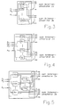
- a particularly simple embodiment of the invention consists in the antenna signals A 1 to A n that the antenna distributor 1 are supplied as input signals, in the antenna distributor 1 by means of passive networks 6a to 6n to feed the antenna switches 2a and 2b in the same number (see FIG. 2).
- the networks 6a to 6n have the task of dividing the antenna signals in their performance as equally as possible between two outputs and decoupling the respective two outputs as well as possible so that the switching state of the antenna switch has a sufficiently low reaction on the respective other output. These requirements are to a large extent z.
- B. Wilkinson coupler which can be carried out by suitable embodiments according to the prior art sufficiently broadband and have the decoupling attenuations of greater than 20 dB.
- Such a passive network for reaction-free signal distribution is complicated in its construction, it takes up a lot of space and is expensive to manufacture. Therefore, with greater signal power losses, there are also networks for signal splitting which, with the help of resistors, enable the outputs to be decoupled, with the advantage that in addition to the simple and therefore inexpensive implementation, they can also easily cover the required bandwidth.
- Such asymmetrical power dividers usually have decoupling values of 12 dB with simultaneous signal attenuation of 6 dB. However, the associated loss of sensitivity can often not be accepted.
- the conditions are much more favorable if the signal distribution in the antenna distributor 1 is carried out by means of active circuits 10a to 10n (see FIG. 3).
- active circuits 10a to 10n see FIG. 3
- Such highly linear and low-noise broadband circuits have decouplings greater than 25 dB up to 1 GHz according to the prior art.
- these active networks allow a signal increase, so that any signal attenuation, e.g. B. in the antenna switch, can be compensated.
- the active circuits can compensate for the loss of signal that inevitably occurs in passive power dividers by the internal amplification.
- active and passive networks are also useful (see FIG. 4) if, for. B. active and passive antennas can be mounted on the vehicle.
- the passive antenna signals can then be supplied to the antenna switches via active signal distributors 10 in order to counteract a further signal deterioration which would result from a signal distribution by means of resistance networks, while the signals of the active antennas are already generated by their noise-matched amplifiers attached to the base of the antenna experience an improvement in their signal-to-noise ratio and a level increase, can be distributed inexpensively to the antenna switch using passive networks 6.
- the output signal y of a circuit 11 for forming a linear combination is determined by the formation rule determined, where x i represents the i-th input signal and a i its complex linear coefficient with which this input signal is evaluated in the circuit 11.
- the output signals of the linear combination circuits can also be fed to the antenna switch, it is advisable because of the greater flexibility involved, to use active signal distributors in the antenna distributor 1 for the antenna signals, since these signals must also be supplied to the linear combination circuits. Only in exceptional cases will you use passive signal distributors, especially if you can afford to accept greater signal attenuation. In principle, all available antenna signals can be used when forming the linear combinations.
- the linear coefficients which are complex in the most general case, will be specified according to amount and phase.
- the amount and phase of the individual linear coefficients can be determined by test drives, in which the efficiency is greatest in terms of minimizing reception interference.
- a particularly simple form of the linear combination is the formation of sums and differences from the input signals.
- the number of signals offered to the antenna switch can vary in the interest of minimizing effort. This affects not only the number of circuits to form linear combinations, but also the number of antenna signals themselves.
- the application of the invention has the further advantage that the wiring in the vehicle is considerably simplified since only the coaxial cables of the broadband antennas installed on the vehicle have to be routed to an antenna distributor to be attached at a suitable location.
- the different tuners for the different reception tasks are expediently installed at the same installation location and thus the effort for the additional tuners is reduced.
- the image oscillator of the image tuner can also be used as an oscillator for the television tuner when the signal evaluation on the audio IF of 33.4 MHz takes place in the associated diversity processor.
- this signal on z. B. implemented 10.7 MHz could then e.g. B. this frequency-modulated television sound signal can be switched to the radio IF of 10.7 MHz of a radio available for VHF diversity reception and the sound reproduction device of this radio would also Can be used for the sound reproduction of the television sound.
- the diversity processor originally used only for VHF diversity reception could thus also be used for diversity reception of the television sound, in which case the control line which leads from the diversity processor is connected to the antenna switch for receiving the television sound. In the case of radio reception, this control line would be connected to the antenna switch for receiving the FM radio. This double use of the radio and the associated diversity processor significantly reduces the technical effort.
- the television sound signal is usually only demodulated on the frequency of 5.5 MHz after the demodulation of the image signal.
- the signal evaluation of the television sound in the diversity processor can also take place at this frequency.
Abstract
Description
Die Erfindung betrifft eine Antennendiversity-Anlage mit mindestens zwei Antennen für den mobilen Empfang von Meter- und Detimeterwellen nach dem Oberbegriff des Anspruchs 1.The invention relates to an antenna diversity system with at least two antennas for the mobile reception of meter and detimeter waves according to the preamble of
Durch Mehrwegeausbreitung werden beim mobilen Rundfunk- und Fernsehempfang erhebliche Empfangsstörungen verursacht, die im Falle des Tonrundfunkempfangs durch Aufrauschen und ausgeprägte Verzerrungen des niederfrequenten Signals den Hörgenuß stark beeinträchtigen und im Falle des Fernsehempfangs durch Geisterbilder, Bildflattern, Farbfading, Verlust der Synchronisation und Bildausfall störend in Erscheinung treten. Solche Empfangsstörungen beeinträchtigen in erheblichem Maße die Empfangsqualität; sie sind daher zu vermeiden.Multipath propagation causes considerable reception interference in mobile radio and television reception, which in the case of audio broadcast reception due to noise and pronounced distortion of the low-frequency signal severely impair the listening pleasure and in the case of television reception through ghosting, image flutter, color fading, loss of synchronization and loss of picture to step. Such reception disturbances affect the reception quality considerably; they should therefore be avoided.
Aus der deutschen Patentanmeldung DE-A-35 17 247 ist eine Antennendiversity-Anlage zur Elimination von Empfangsstörungen beim frequenzmodulierten UKW-Tonrundfunk bekannt. Hierbei werden einem Diversity-Prozessor mindestens zwei Antennensignale zugeführt, wobei im Diversity-Prozessor eine Frequenzhubschwelle und eine Amplitudenschwelle enthalten sind, mit denen jeweils die aktuell störungsbedingten Frequenzstörhubpulse bzw. die störungsbedingten Amplitudeneinbrüche im Zwischenfrequenzsignal, das dem Diversity-Prozessor aus dem Empfänger zugeführt wird, verglichen werden. Überschreiten die Störungen die Schwellen, wird ein Umschaltvorgang eingeleitet, derart, daß ein anderes Antennensignal oder eine andere aus den Antennensignalen abgeleitete lineare Kombination dem Tuner mit ZF-Teil zugeführt wird.From the German patent application DE-A-35 17 247 an antenna diversity system for eliminating interference in frequency-modulated VHF radio broadcasting is known. In this case, a diversity processor is supplied with at least two antenna signals, the diversity processor containing a frequency deviation threshold and an amplitude threshold, with each of which the current interference-induced frequency interference pulse pulses or the interference-induced amplitude drops in the intermediate frequency signal, which is supplied to the diversity processor from the receiver, be compared. If the interference exceeds the thresholds, a switchover process is initiated such that another antenna signal or another linear combination derived from the antenna signals is fed to the tuner with the IF part.
Eine Antennendiversity-Anlage zur Vermeidung von Bildstörungen beim mobilen Empfang von Fernsehsignalen im Meter- und Dezimeterwellenbereich wird in der deutschen Patentanmeldung DE-A-39 26 336 (veröffentlicht am 14.02.91) angegeben. Diese Antennendiversity-Anlage umfaßt einen Diversity-Prozessor mit N Antennensignaleingängen una einen Fernsehempfänger, wobei dem Diversity-Prozessor das Videosignal sowie die horizontalen und vertikalen Synchronsignale zugeführt werden. Im Diversity-Prozessor ist eine Zeittorschaltung enthalten, die durch die horizontalen Synchronimpulse während der horizontalen Austastzeit geöffnet wird, wodurch das Videosignal zur Signalqualitätsbewertung durchgeschaltet wird. Über eine Steuerschaltung wird ein Adreßsignal bei einer sich anbahnenden Bildstörung erzeugt, derart, daß über einen Antennencombiner ein neues Antennensignal oder eine andere aus den Antennensignalen abgeleitete lineare Kombination dem Fernsehempfänger zugeführt wird.An antenna diversity system to avoid picture interference during mobile reception of television signals in the meter and decimeter wave range is specified in German patent application DE-A-39 26 336 (published on February 14, 1991). This antenna diversity system includes a diversity processor with N antenna signal inputs and a television receiver, the diversity processor being supplied with the video signal and the horizontal and vertical synchronizing signals. The diversity processor contains a time gate which is opened by the horizontal synchronizing pulses during the horizontal blanking time, as a result of which the video signal is switched through for signal quality evaluation. An address signal is generated via a control circuit in the event of impending picture interference, in such a way that a new antenna signal or another linear combination derived from the antenna signals is fed to the television receiver via an antenna combiner.
Jede der in den oben genannten Patentanmeldungen beschriebenen Diversity-Anlagen löst die Aufgabe, die durch Mehrwegeausbreitung verursachten Empfangsstörungen in einem Ton- oder einem Fernsehkanal zu reduzieren. Möchte man jedoch in einem Fahrzeug neben dem Fernsehbild auch den Fernsehton verbessern, so setzt dies nach dem Stand der Technik separate Antennen und damit auch separate Antennendiversity-Anlagen sowohl für den Fernsehempfang als auch für den Tonempfang voraus. Denn bei Anwendung der in DE-A-39 26 336 angegebenen Lösung werden die Bildstörungen beim mobilen Empfang vermieden, nicht jedoch die Tonstörungen des dazugehörigen Fernsehtons. Dies liegt zum einen darin begründet, daß das Fernsehbild in spezieller Weise amplitudenmoduliert ist, während der Fernsehton frequenzmoduliert ist und die Kriterien zur Feststellung der Bildqualität prinzipiell völlig anders geartet sind als die Kriterien zur Feststellung einer Tonstörung. Zum andern bedingt der Frequenzabstand von 5.5 MHz zwischen Bild- und Tonträger, daß bei einem derartig großen Frequenzabstand die Empfangsverhältnisse am Ort einer Empfangsantenne für Bild- und Tonträger völlig unterschiedlich sind mit der Folge, daß z. B. die Bildstörung maximal und die Tonträgerstörung gleichzeitig minimal sein kann.Each of the diversity systems described in the above-mentioned patent applications solves the task of reducing the reception interference caused by multipath propagation in a sound or a television channel. However, if one would also like to improve the television sound in a vehicle in addition to the television picture, this requires separate antennas according to the prior art and thus also separate antenna diversity systems both for television reception and for sound reception. This is because when using the solution specified in DE-A-39 26 336, the picture interference during mobile reception is avoided, but not the sound interference of the associated television sound. On the one hand, this is due to the fact that the television picture is amplitude-modulated in a special way, while the television sound is frequency-modulated and the criteria for determining the picture quality are fundamentally completely different from the criteria for determining a sound disturbance. On the other hand, the frequency spacing of 5.5 MHz between image and sound carriers means that with such a large frequency spacing, the reception conditions at the location of a receiving antenna for image and sound carriers are completely different, with the result that, for. B. the image disturbance can be maximal and the sound carrier disturbance can be minimal at the same time.
Dies bedeutet, daß bei Anwendung der oben genannten Lösungen nach dem Stand der Technik mindestens vier Antennen am Fahrzeug angebracht sein müssen. Um jedoch eine deutliche Verbesserung des Empfangs zu erhalten, wird in der Literatur eine Anzahl von vier Antennen pro Diversityeinrichtung empfohlen mit der Folge, daß nach dem Stand der Technik bereits acht Antennen am Fahrzeug montiert werden müssen, um Bild- und Tonstörungen während der Fahrt effizient zu eliminieren. Wollte man den in zwei durch eine Frequenzlücke getrennten Bändern übertragenen Stereofernsehton ebenfalls durch Antennendiversity verbessern, müßte man demzufolge mindestens 12 Antennen am Fahrzeug anbringen. Berücksichtigt man weiter die enorme abzudeckende Frequenzbandbreite von ca. 40 bis 860 MHz, so kommt erschwerend hinzu, daß mit einer einzelnen Antenne dieser große Frequenzbereich schwierig abzudecken ist, so daß die benötigte Antennenzahl durch Verwendung von Bereichsantennen noch weiter ansteigt. Eine solche Vielzahl von Antennen läßt sich aber an modernen Kraftfahrzeugen nicht unterbringen.This means that when using the above-mentioned solutions according to the prior art, at least four antennas must be attached to the vehicle. However, in order to obtain a significant improvement in reception, a number of four antennas per diversity device is recommended in the literature, with the result that that according to the prior art, eight antennas must already be mounted on the vehicle in order to efficiently eliminate image and sound interference while driving. If one also wanted to improve the stereo television sound transmitted in two bands separated by a frequency gap by antenna diversity, one would have to attach at least 12 antennas to the vehicle. If one further takes into account the enormous frequency bandwidth of approx. 40 to 860 MHz to be covered, it is further aggravated that this large frequency range is difficult to cover with a single antenna, so that the number of antennas required increases even further by using area antennas. Such a large number of antennas cannot be accommodated in modern motor vehicles.
Aufgabe der Erfindung ist es deshalb, eine Antennendiversity-Anlage für den mobilen Empfang von Meter- und Dezimeterwellen anzugeben, die es mit einer nicht zu großen Zahl von Antennen ermöglicht, ein und denselben Satz von Antennen zur Versorgung von zwei oder mehr Tunern, von denen jeder unterschiedliche Empfangsanforderungen besitzt, zu verwenden, wobei gewährleistet sein soll, daß sich jeweils für jeden Tuner die für ihn günstigsten Diversity-Empfangsverhältnisse einstellen lassen.The object of the invention is therefore to provide an antenna diversity system for the mobile reception of meter and decimeter waves, which makes it possible with a not too large number of antennas, one and the same set of antennas to supply two or more tuners, one of which each has different reception requirements to be used, it should be ensured that the most favorable diversity reception ratios can be set for each tuner.
Diese Aufgabe wird bei einer gattungsgemäßen Anlage durch die kennzeichnenden Merkmale des Anspruchs 1 gelöst.This object is achieved in a generic system by the characterizing features of
Solche Antennendiversity-Anlagen werden vorzugsweise zur Verbesserung des Fernseh- und Tonempfangs im Meter- und Dezimeterwellenbereich in Kraftfahrzeugen verwendet.Antenna diversity systems of this type are preferably used to improve television and sound reception in the meter and decimeter wave range in motor vehicles.
Die mit der Erfindung erzielbaren Vorteile bestehen in der erheblichen Reduzierung der Antennenzahl für Antennendiversity-Anlagen, deren Tuner für ganz unterschiedliche Empfangsanforderungen eingesetzt werden. So reicht bei erfindungsgemäßer Ausbildung ein Satz von z. B. vier Antennen aus, um sowohl die Empfangsstörungen des Stereofernsehtons und des Fernsehbildes als auch die Empfangsstörungen beim UKW-Rundfunk zu unterdrükken. Dadurch wird überhaupt erst die Möglichkeit in einem Kraftfahrzeug geschaffen, mehrere Diversity-Einrichtungen gleichzeitig zu betreiben. Bekanntermaßen würde eine große Anzahl von Antennen bei der heutigen Kompaktbauweise moderner Kraftfahrzeuge gar nicht mehr auf oder am Fahrzeug untergebracht werden können, von der Schwierigkeit der Verkabelung und den enormen Kosten einmal ganz abgesehen. Die erfindungsgemäße Antennendiversity-Anlage besitzt beim Fernsehbild- und Tonempfang den weiteren Vorteil, daß durch den kompakten Aufbau z. B. der Oszillator des Bildtuners auch für den Tontuner verwendet werden kann, wodurch wiederum Kosten eingespart werden können.The advantages that can be achieved with the invention consist in the considerable reduction in the number of antennas for antenna diversity systems, the tuners of which are used for very different reception requirements. So with training according to the invention a set of z. B. four antennas to suppress both the reception interference of the stereo television and the television picture as well as the reception interference in FM radio. This creates the possibility in a motor vehicle to operate several diversity devices simultaneously. As is known, a large number would of antennas in today's compact design of modern motor vehicles can no longer be accommodated on or on the vehicle, apart from the difficulty of the wiring and the enormous costs. The antenna diversity system according to the invention has the further advantage in television picture and sound reception that z. B. the oscillator of the picture tuner can also be used for the tone tuner, which in turn can save costs.
Ausführungsbeispiele der Erfindung werden an Hand der folgenden Figuren näher erläutert:
- Fig. 1: Erfindungsgemäße Antennendiversity-Anlage, bestehend aus einem Antennenverteiler, zwei Antennenumschaltern, zwei Tunern sowie zwei Diversity-Prozessoren
- Fig. 2: Antennenverteiler in einer Antennendiversity-Anlage nach Fig. 1, bestehend aus passiven Netzwerken
- Fig. 3: Antennenverteiler in einer Antennendiversity-Anlage nach Fig. 1, bestehend aus aktiven Schaltungen
- Fig. 4: Antennenverteiler in einer Antennendiversity-Anlage nach Fig. 1, bestehend aus aktiven Schaltungen und passiven Netzwerken
- Fig. 5: Antennenverteiler in einer Antennendiversity-Anlage nach Fig. 1, bestehend aus aktiven und passiven Netzwerken zur Signalaufteilung und Netzwerken zur Bildung von Linearkombinationen
- Fig. 6: Antennendiversity-Anlage zur Vermeidung von Empfangsstörungen beim Empfang des Stereofernsehtons und des Fernsehbildes
- Fig. 7.: Antennendiversity-Anlage zur Vermeidung von Empfangsstörungen beim Empfang des Stereofernsehtons und des Fernsehbildes sowie eines UKW-Rundfunkkanals
- Fig. 8: Mitbenutzung des Oszillatorsignals des Bildtuners für den Empfang des dazugehörigen Fernsehtons eines Fernsehkanals
- Fig. 1: Antenna diversity system according to the invention, consisting of an antenna distributor, two antenna switches, two tuners and two diversity processors
- Fig. 2: Antenna distributor in an antenna diversity system according to Fig. 1, consisting of passive networks
- 3: antenna distributor in an antenna diversity system according to FIG. 1, consisting of active circuits
- Fig. 4: Antenna distributor in an antenna diversity system according to Fig. 1, consisting of active circuits and passive networks
- 5: Antenna distributor in an antenna diversity system according to FIG. 1, consisting of active and passive networks for signal distribution and networks for the formation of linear combinations
- Fig. 6: Antenna diversity system to avoid reception interference when receiving stereo television and the television picture
- Fig. 7 .: Antenna diversity system to avoid reception interference when receiving the stereo television and the television picture and an FM radio channel
- Fig. 8: shared use of the oscillator signal of the image tuner for the reception of the associated television sound of a television channel
In Fig. 1 ist eine erfindungsgemäße Antennendiversity-Anlage dargestellt. Sie besteht aus einem Satz von N Antennen A1 bis AN, die den Eingängen des Antennenverteilers 1 zugeführt sind. Die Ausgänge des Antennenverteilers führen die Antennensignale und sind den zwei Antennenumschaltern 2a und 2b zugeführt. In den Antennenumschaltern wird jeweils mittels einer Steuerleitung 3a bzw. 3b jeweils ein Ausgangssignal des Antennenverteilers 1 ausgewählt und zum Tuner 4a bzw. 4b durchgeschaltet. Der Tuner 4a kann, wie in Fig. 1 dargestellt, z. B. ein Fernsehbildtuner sein. Im Tuner 4a wird das HF-Signal 7a auf eine Zwischenfrequenz umgesetzt und demoduliert, so daß dessen Videosignal und ggfs. weitere Signale als demoduliertes Signal 8a einem Diversity-Prozessor zugeführt werden können. Im Diversity-Prozessor wird in bekannter Weise, z. B. über eine Zeittorschaltung (s. DE-A-39 26 336), in der horizontalen Austastzeit die aktuelle Bildqualität mit einer Schwelle verglichen und bei Bedarf die Steuerleitung 3a so gesetzt, daß der Antennenumschalter 2a veranlaßt wird, auf ein anderes Ausgangssignal des Antennenverteilers 1 umzuschalten. Auf diese Weise wird sichergestellt, daß immer das jeweils mit der besten Bildqualität zur Verfügung stehende HF-Signal zum Tuner 4a durchgeschaltet ist.1 shows an antenna diversity system according to the invention. It consists of a set of N antennas A 1 to AN, which are fed to the inputs of the
Der Tuner 4b in Fig. 1 ist auf den Fernsehton des gleichen Fernsehkanals abgestimmt. Das frequenzmodulierte, noch nicht begrenzte ZF-Signal wird dem Diversity-Prozessor 9b zugeführt. Im Diversity-Prozessor werden die störungsbedingten Frequenzstörhubspitzen und die Amplitudeneinbrüche in bekannter Weise (s. DE-A-35 17 247) mit Schwellen verglichen. Bei einer Tonstörung wird der Antennenumschalter 2b über die Steuerleitung 3b veranlaßt, ein besseres Fernsehtonsignal zum Tuner 4b durchzuschalten. Mit Hilfe einer solchen Antennendiversity-Anlage wird unabhängig voneinander sichergestellt, daß zu jedem Zeitpunkt sowohl das Fernsehbild als auch der dazugehörige Fernsehton jeweils am wenigsten gestört ist, dadurch, daß der jeweilige Tuner unabhängig von den andern Tunern auf alle zur Verfügung stehenden Antennensignale zugreifen kann.The
Durch Einführung des Stereotons bzw. des Zweikanaltons beim Fernsehen, deren Tonträger einen Abstand von 242 kHz aufweisen, wird ein weiterer Tuner 4c erforderlich (s. Fig. 6), da bei diesem Frequenzabstand, der größer als der Kanalabstand beim UKW-Rundfunk ist, die Empfangssignale am Ort der Antennen bereits deutlich unterschiedlichen Verlauf über der Zeit aufweisen, wie Messungen zeigen. Auch für den zweiten Tonkanal wird die Tonstörung nach den beschriebenen Verfahren beseitigt.By introducing the stereo sound or the two-channel sound on television, the sound carriers of which have a spacing of 242 kHz, a
Ein weiterer Vorteil bei erfindungsgemäßen Antennendiversity-Anlagen besteht darin, daß z. B. bei Luxuslimousinen neben der Möglichkeit des Fernsehempfangs mit Stereoton auch noch UKW-Rundfunkempfang mit demselben Satz von Antennensignalen ermöglicht wird. Hierbei kann das serienmäßige Autoradio als Tuner 4d eingesetzt werden (s. Fig. 7). Auch hier wird in bekannter Weise das frequenzmodulierte ZF-Signal 8d im Diversity-Prozessor 9d auf Empfangsstörungen hin untersucht und es werden Empfangsstörungen durch schnelles Umschalten auf ein ungestörtes Signal vermieden.Another advantage with antenna diversity systems according to the invention is that z. B. in luxury sedans in addition to the possibility of television reception with stereo sound, FM radio reception with the same set of antenna signals is also possible. The standard car radio can be used as a
Eine besonders vorteilhafte Ausgestaltung der Erfindung besteht darin, daß mehrere FM-Tuner für den frequenzmodulierten UKW-Rundfunk an die jeweiligen Antennenumschalter angeschlossen sind. Auf diese Weise wird es z. B. beim Radioempfang in Omnibussen ermöglicht, daß dem Fahrgast mehrere Radioprogramme über Kopfhörer bei individueller Auswahl des Programms angeboten werden können, wobei jedes Programm für sich durch Antennendiversity weitestgehend störungsfrei beim mobilen Empfang wiedergegeben wird. Die Empfangsverbesserung geschieht dadurch, daß für jedes Radioprogramm ein separater Diversity-Prozessor vorhanden ist, dem das noch nicht begrenzte ZF-Signal zugeführt ist, und daß dann auf an sich bekannte Weise die Empfangsstörungen durch Umschalten auf andere Signale am Antennenumschalter vermieden werden.A particularly advantageous embodiment of the invention consists in that several FM tuners for frequency-modulated VHF radio are connected to the respective antenna switch. In this way it will be e.g. B. in radio reception in buses that the passenger can be offered several radio programs on headphones with individual selection of the program, each program for itself largely reproduced by antenna diversity without interference in mobile reception. The reception improvement occurs in that for each radio program there is a separate diversity processor, to which the IF signal, which is not yet limited, is supplied, and in that the reception interference is avoided in a manner known per se by switching to other signals on the antenna switch.
Eine besonders einfache Ausgestaltung der Erfindung besteht darin, die Antennensignale A1 bis An, die dem Antennenverteiler 1 als Eingangssignale zugeführt sind, im Antennenverteiler 1 mittels passiver Netzwerke 6a bis 6n in gleicher Zahl den Antennenumschaltern 2a und 2b zuzuführen (s. Fig. 2). Die Netzwerke 6a bis 6n haben dabei die Aufgabe, die Antennensignale in ihrer Leistung möglichst gleich auf jeweils zwei Ausgänge aufzuteilen und die jeweiligen beiden Ausgänge möglichst gut voneinander zu entkoppeln, damit der Schaltzustand der Antennenumschalter ausreichend geringe Rückwirkung auf den jeweiligen andern Ausgang besitzt. Diesen Anforderungen werden in hohem Maße z. B. Wilkinsonkoppler gerecht, die durch geeignete Ausführungsformen nach dem Stande der Technik hinreichend breitbandig ausgeführt werden können und die Entkoppeldämpfungen von größer 20 dB aufweisen.A particularly simple embodiment of the invention consists in the antenna signals A 1 to A n that the
Ein solches passives Netzwerk zur rückwirkungsfreien Signalaufteilung ist jedoch in seinem Aufbau kompliziert, von großem Raumbedarf und teuer in der Herstellung. Deshalb bieten sich unter Inkaufnahme von größeren Signalleistungsverlusten auch Netzwerke zur Signalaufteilung an, die mit Hilfe von Widerständen eine Entkopplung der Ausgänge ermöglichen mit dem Vorteil, neben der einfachen und damit kostengünstigen Realisierung gleichzeitig problemlos die erforderliche Bandbreite abzudecken. Solche asymmetrischen Leistungsteiler weisen meist Entkopplungswerte von 12 dB bei gleichzeitiger Signaldämpfung um 6 dB auf. Der damit verbundene Empfindlichkeitsverlust kann jedoch häufig nicht hingenommen werden.Such a passive network for reaction-free signal distribution is complicated in its construction, it takes up a lot of space and is expensive to manufacture. Therefore, with greater signal power losses, there are also networks for signal splitting which, with the help of resistors, enable the outputs to be decoupled, with the advantage that in addition to the simple and therefore inexpensive implementation, they can also easily cover the required bandwidth. Such asymmetrical power dividers usually have decoupling values of 12 dB with simultaneous signal attenuation of 6 dB. However, the associated loss of sensitivity can often not be accepted.
In dieser Hinsicht wesentlich günstigere Verhältnisse liegen vor, wenn die Signalaufteilung im Antennenverteiler 1 mittels aktiver Schaltungen 10a bis 10n erfolgt (s. Fig. 3). Solche hochlinearen und rauscharmen Breitbandschaltungen weisen nach dem Stand der Technik dabei Entkopplungen größer 25 dB bis zu 1 GHz auf. Gleichzeitig erlauben diese aktiven Netzwerke eine Signalanhebung, so daß etwaige Signaldämpfungen, z. B. im Antennenumschalter, ausgeglichen werden können. Zudem kann durch die aktiven Schaltungen der Signalverlust, der zwangsweise bei passiven Leistungsteilern auftritt, durch die innere Verstärkung kompensiert werden.In this respect, the conditions are much more favorable if the signal distribution in the
Für den Antennenverteiler 1 ist aber auch eine Kombination aktiver und passiver Netzwerke sinnvoll (s. Fig. 4), wenn z. B. aktive und passive Antennen am Fahrzeug montiert werden. So können dann die passiven Antennensignale über aktive Signalverteiler 10 den Ant:ennenumschaltern zugeführt werden, um einer weiteren Signalverschlechterung entgegenzuwirken, die sich bei einer Signalaufteilung mittels Widerstandsnetzwerken ergäbe, während die Signale der aktiven Antennen, die durch ihren im Fußpunkt der Antenne angebrachten rauschangepaßten Verstärker bereits eine Verbesserung ihres Signalrauschabstands und eine Pegelanhebung erfahren, mittels passiver Netzwerke 6 kostengünstig auf die Antennenumschalter verteilt werden können.For the
Umfangreiche Untersuchungen haben gezeigt, daß die durch Mehrwegeausbreitung verursachten Ton- und Bildstörungen beim mobilen Empfang im Meter- und Dezimeterwellenbereich weiter reduziert werden können, wenn zu den Antennensignalen selbst weitere durch Linearkombination der vorhandenen Antennensignale entstandene Signale den Antennenumschaltern zugeführt werden. Hierbei wird, wie in Fig. 5 gezeigt, das Ausgangssignal y einer Schaltung 11 zur Bildung einer Linearkombination durch die Bildungsvorschrift
Dabei werden die Linearkoeffzienten, die im allgemeinsten Fall komplex sind, nach Betrag und Phase vorgegeben sein. Die Festlegung des Betrages und der Phase der einzelnen Linearkoeffizienten kann dabei durch Testfahrten erfolgen, bei denen die Effizienz am größten ist im Hinblick auf die Empfangsstörungsminimierung.The linear coefficients, which are complex in the most general case, will be specified according to amount and phase. The amount and phase of the individual linear coefficients can be determined by test drives, in which the efficiency is greatest in terms of minimizing reception interference.
Eine besonders einfache Form der Linearkombination stellt die Summen- und Differenzbildung aus den Eingangssignalen dar. Hierbei müssen nicht zwangsweise alle Eingangssignale verwendet werden, vielmehr können z. B. nur besonders starke Antennensignale herangezogen werden. Dieses Vorgehen entspricht dann einem Fall, in dem die entsprechenden Linearkoeffizienten der nicht verwendeten Antennensignale zu Null gewählt sind.A particularly simple form of the linear combination is the formation of sums and differences from the input signals. Here, not all input signals necessarily have to be used; B. only particularly strong antenna signals are used. This procedure then corresponds to a case in which the corresponding linear coefficients of the antenna signals not used are chosen to be zero.
Die Zahl der Signale, die den Antennenumschaltern angeboten wird, kann durchaus im Interesse der Aufwandsminimierung unterschiedlich sein. Dies betrifft nicht nur die Anzahl der Schaltungen zur Bildung von Linearkombinationen sondern auch die Zahl der Antennensignale selbst.The number of signals offered to the antenna switch can vary in the interest of minimizing effort. This affects not only the number of circuits to form linear combinations, but also the number of antenna signals themselves.
Die Anwendung der Erfindung bringt den weiteren Vorteil mit sich, daß die Verkabelung im Fahrzeug erheblich vereinfacht wird, da lediglich die Koaxialkabel der am Fahrzeug installierten Breitbandantennen zu einem an einem geeigneten Ort anzubringenden Antennenverteiler geführt werden müssen. Zweckmäßigerweise werden am gleichen Einbauort auch die verschiedenen Tuner für die unterschiedlichen Empfangsaufgaben eingebaut und damit reduziert sich der Aufwand für die zusätzlichen Tuner, denn es kann z. B., wie Fig. 8 zeigt, der Bildoszillator des Bildtuners gleichzeitig auch als Oszillator für den Fernsehtontuner verwendet werden, wenn die Signalauswertung auf der Ton-ZF von 33.4 MHz im zugeordneten Diversity-Prozessor erfolgt.The application of the invention has the further advantage that the wiring in the vehicle is considerably simplified since only the coaxial cables of the broadband antennas installed on the vehicle have to be routed to an antenna distributor to be attached at a suitable location. The different tuners for the different reception tasks are expediently installed at the same installation location and thus the effort for the additional tuners is reduced. B., as shown in FIG. 8, the image oscillator of the image tuner can also be used as an oscillator for the television tuner when the signal evaluation on the audio IF of 33.4 MHz takes place in the associated diversity processor.
Wird durch einen weiteren Festoszillator dieses Signal auf z. B. 10.7 MHz umgesetzt, könnte dann z. B. dieses frequenzmodulierte Fernsehtonsignal auf die Radio-ZF von 10.7 MHz eines zum UKW-Diversityempfang vorhandenen Radios geschaltet werden und die Tonwiedergabeeinrichtung dieses Radios würde auch für die Tonwiedergabe des Fernsehtons verwendet werden Können. Damit könnte auch der ursprünglich nur zum UKW-Diversityempfang verwendete Diversity-Prozessor auch zum Diversityempfang des Fernsehtons verwendet werden, wobei dann die Steuerleitung, die aus dem Diversity-Prozessor führt, mit dem Antennenumschalter zum Empfang des Fernsehtons verbunden wird. Im Falle des Radioempfangs wäre diese Steuerleitung mit dem Antennenumschalter zum Empfang des UKW-Rundfunks verbunden. Durch diese Doppelnutzung des Radios und des zugeordneten Diversity-Prozessors wird der technische Aufwand erheblich reduziert.Is this signal on z. B. implemented 10.7 MHz, could then e.g. B. this frequency-modulated television sound signal can be switched to the radio IF of 10.7 MHz of a radio available for VHF diversity reception and the sound reproduction device of this radio would also Can be used for the sound reproduction of the television sound. The diversity processor originally used only for VHF diversity reception could thus also be used for diversity reception of the television sound, in which case the control line which leads from the diversity processor is connected to the antenna switch for receiving the television sound. In the case of radio reception, this control line would be connected to the antenna switch for receiving the FM radio. This double use of the radio and the associated diversity processor significantly reduces the technical effort.
In Fernsehempfängern für den Heimempfang wird üblicherweise das Fernsehtonsignal erst nach der Demodulation des Bildsignals demoduliert auf der Frequenz von 5.5 MHz. Selbstverständlich kann bei einer erfindungsgemäßen Antennendiversity-Anlage die Signalbewertung des Fernsehtons im Diversity-Prozessor auch auf dieser Frequenz erfolgen.In television receivers for home reception, the television sound signal is usually only demodulated on the frequency of 5.5 MHz after the demodulation of the image signal. Of course, in an antenna diversity system according to the invention, the signal evaluation of the television sound in the diversity processor can also take place at this frequency.
Claims (19)
- Antenna diversity system comprising at least two antennae (Al, A2) for the mobile reception of meter and decimeter waves, consisting of an antenna distributor (1) having a set of inputs and a set of outputs, to the inputs of said antenna distributor are transmitted the antenna signals and the output signals of said antenna distributor are transmitted to an antenna duplexer (2a), and consisting of a tuner (4a), to which the selected HF signal is transmitted from the antenna duplexer (2a), wherein the tuner (4a) has an output which guides the IF signal or the demodulated signal (8a) and which is connected to a diversity processor (9a), in which a signal evaluation process is performed, the result of which determines whether a control line (3a) which leads from the diversity processor (9a) to the antenna duplexer (2a) causes the antenna duplexer (2a) to switch through a more favourable input signal to its output, characterised in that the antenna distributor (1) comprises at least one further set of outputs, each further set of outputs being connected to a dedicated antenna duplexer (2b), the output of which is connected in each case to a dedicated tuner (4b) which has an output which guides the IF signal or the demodulated signal (8b) to a diversity processor (9b) which is allocated to this tuner (4b) and performs a signal evaluation process which is tailored to suit the allocated tuner (4b) and owing to which signal evaluation process the allocated antenna duplexer (2b) is controlled by way of a control line (3b) in such a manner that said duplexer switches through a more favourable input signal to its output.
- Antenna diversity system according to claim 1, characterised in that the antenna distributor (1) comprises a total of two sets of outputs (1...n, 1...m), wherein tuner (4a) which is connected to the one set of outputs by way of its antenna duplexer (2a) receives the television picture of a television channel, whereas the tuner (4b) which is connected to the other set of outputs by way of its antenna duplexer (2b) receives the associated television sound.
- Antenna diversity system according to claim 2, characterised in that the tuner (4a), which receives the television picture, guides at its output the demodulated signal (8a) and the tuner (4b), which receives the television sound, guides at its output the as yet unlimited IF tone signal (8b).
- Antenna diversity system according to claim 1, characterised in that the antenna distributor (1) comprises a total of three sets of outputs (1...n; 1...m; 1...o), wherein the tuner (4a) which is connected to the one set of outputs by way of its antenna duplexer (2a) receives the television picture of a television channel, whereas the tuners (4b and 4c) which are connected to the other two sets of outputs in each case by way of an antenna duplexer (2b and 2c) each receive one of the two frequency separated HF signals of the stereophonic television sound or of the dual channel sound.
- Antenna diversity system according to any one of the claims 2 to 4, characterised in that the antenna distributor (1) also comprises at least one further set of outputs (1...p) which is connected in each case by way of an antenna duplexer (2d) to a tuner (4d) for the purpose of receiving frequency modulated radio broadcasting.
- Antenna diversity system according to any one of the claims 2 to 5, characterised in that the oscillator signal of the tuner (4a) which receives the television picture is also the oscillator signal of the tuner (4b) which receives the television sound.
- Antenna diversity system according to claim 1, characterised in that at least some of the tuners are FM tuners, of which at least one is used to receive a frequency modulated radio broadcasting channel and at least one is used to receive frequency modulated television sound.
- Antenna diversity system according to daim 7, characterised in that the said FM tuners transmit at their output the as yet unlimited IF signal to the allocated diversity processor (9a, b, c).
- Antenna diversity system according to claim 8, characterised in that the signal evaluation process is performed in the diversity processors (9a, b, c) by virtue of the coincidence of amplitude troughs and interference frequency swing peaks of the as yet unlimited IF signal.
- Antenna diversity system according to any one of the claims 7 to 9, characterised in that the signal evaluation process is performed in the diversity processors (9a, b, c) upon the frequency modulated television sound being received on the standardised IF-audio-frequencies 33.4 MHZ, 10.7 MHZ or 5.5 MHZ.
- Antenna diversity system according to any one of the claims 2 to 6, characterised in that the signal evaluation process is performed in the diversity processor (9a), which is allocated to the tuner (4a) receiving the television picture, during a horizontal or vertical blanking period of the demodulated picture signal.
- Antenna diversity system according to any one of the claims 1 to 11, characterised in that in the antenna distributor (1) all antenna signals are distributed by means of passive networks (6a, 6b, ..., 6n) to the inputs of the antenna duplexers (2a, 2b).
- Antenna diversity system according to any one of the claims 1 to 11, characterised in that in the antenna distributor (1) all antenna signals are distributed by means of active circuits (10a, 10b, ..., 10n) to the inputs of the antenna duplexers (2a, 2b).
- Antenna diversity system according to any one of the claims 1 to 11, characterised in that in the antenna distributor (1) some of the antenna signals are distributed by means of passive networks (6a, 6b 6i) and the remaining antenna signals are distributed by means of active circuits (10a, 10b, ..., 10j) to the inputs of the antenna duplexers.
- Antenna diversity system according to any one of the claims 1 to 14, characterised in that in the antenna distributor (1) there are provided circuits (11a, b) in which linear combinations are formed from the antenna signals and the output signals of these circuits (11a, b) in addition to the antenna signals are transmitted to the antenna duplexers.
- Antenna diversity system according to claim 15, characterised in that the coefficients of the linear combinations are fixed according to value and phase.
- Antenna diversity system according to claim 15, characterised in that one or more coefficients of a linear combination are selected to be zero.
- Antenna diversity system according to any one of the claims 1 to 17, characterised in that the number of signals, which are transmitted to the antenna duplexers, varies per antenna duplexer (2a, 2b).
- Antenna diversity system according to claim 18, which is dependent upon any one of the claims 15 to 17, characterised in that the number of transmitted signals and the number of transmitted output signals of the circuits (11a, b), in which linear combinations are formed, are different.
Applications Claiming Priority (3)
| Application Number | Priority Date | Filing Date | Title |
|---|---|---|---|
| DE4101629A DE4101629C3 (en) | 1991-01-21 | 1991-01-21 | Antenna diversity system with at least two antennas for the mobile reception of meter and decimeter waves |
| DE4101629 | 1991-01-21 | ||
| PCT/EP1992/000104 WO1992013399A1 (en) | 1991-01-21 | 1992-01-20 | Aerial diversity installation with at least two aerials for the mobile reception of metre and decimetre waves |
Publications (3)
| Publication Number | Publication Date |
|---|---|
| EP0521123A1 EP0521123A1 (en) | 1993-01-07 |
| EP0521123B1 true EP0521123B1 (en) | 1997-10-22 |
| EP0521123B2 EP0521123B2 (en) | 2001-07-18 |
Family
ID=6423395
Family Applications (1)
| Application Number | Title | Priority Date | Filing Date |
|---|---|---|---|
| EP92902914A Expired - Lifetime EP0521123B2 (en) | 1991-01-21 | 1992-01-20 | Aerial diversity installation with at least two aerials for the mobile reception of metre and decimetre waves |
Country Status (9)
| Country | Link |
|---|---|
| US (1) | US5313660A (en) |
| EP (1) | EP0521123B2 (en) |
| JP (1) | JP3188698B2 (en) |
| AT (1) | ATE159630T1 (en) |
| DE (1) | DE4101629C3 (en) |
| ES (1) | ES2109992T5 (en) |
| HU (1) | HU213331B (en) |
| RU (1) | RU2116698C1 (en) |
| WO (1) | WO1992013399A1 (en) |
Cited By (2)
| Publication number | Priority date | Publication date | Assignee | Title |
|---|---|---|---|---|
| DE102008031068A1 (en) | 2007-07-10 | 2009-01-15 | Lindenmeier, Heinz, Prof. Dr. Ing. | Antenna diversity system for relatively broadband radio reception in vehicles |
| WO2010078605A1 (en) | 2009-01-09 | 2010-07-15 | Akg Acoustics Gmbh | Method for receiving digital audio data |
Families Citing this family (61)
| Publication number | Priority date | Publication date | Assignee | Title |
|---|---|---|---|---|
| US5740526A (en) * | 1994-06-01 | 1998-04-14 | Bonta; Jeffrey D. | Method and apparatus for selecting two antennas from which to receive a communication signal |
| US5684491A (en) * | 1995-01-27 | 1997-11-04 | Hazeltine Corporation | High gain antenna systems for cellular use |
| US5581260A (en) * | 1995-01-27 | 1996-12-03 | Hazeltine Corporation | Angular diversity/spaced diversity cellular antennas and methods |
| US5574466A (en) * | 1995-03-31 | 1996-11-12 | Motorola, Inc. | Method for wireless communication system planning |
| FI105513B (en) * | 1995-05-24 | 2000-08-31 | Nokia Networks Oy | Reception procedure and recipients |
| US5818543A (en) * | 1995-09-06 | 1998-10-06 | Premier Wireless, Inc. | Diversity receiver for television |
| US5940452A (en) * | 1995-11-29 | 1999-08-17 | Motorola, Inc. | Dual mode radio subscriber unit having a diversity receiver apparatus and method therefor |
| US6421543B1 (en) * | 1996-01-29 | 2002-07-16 | Ericsson Inc. | Cellular radiotelephone base stations and methods using selected multiple diversity reception |
| DE19636125B4 (en) * | 1996-09-06 | 2007-12-06 | Fuba Automotive Gmbh & Co. Kg | Space diversity method and circuitry |
| DE19637327B4 (en) | 1996-09-13 | 2009-04-09 | Delphi Delco Electronics Europe Gmbh | Frequency diversity arrangement |
| JPH10336087A (en) * | 1997-05-30 | 1998-12-18 | Kyocera Corp | Maximum ratio synthesis transmission diversity device |
| JP3614620B2 (en) * | 1997-07-30 | 2005-01-26 | アルプス電気株式会社 | Television signal and FM broadcast signal demodulator and television signal and FM broadcast signal receiver |
| DE19739898C2 (en) * | 1997-09-11 | 1999-07-29 | Becker Gmbh | Multipath reception method |
| US6167039A (en) * | 1997-12-17 | 2000-12-26 | Telefonaktiebolget Lm Ericsson | Mobile station having plural antenna elements and interference suppression |
| US5940454A (en) * | 1997-12-17 | 1999-08-17 | Nortel Networks Corporation | Blind switch diversity control apparatus |
| GB9812429D0 (en) * | 1998-06-09 | 1998-08-05 | Radiant Networks Plc | Transmitter,receiver and transceiver apparatus |
| DE19845534B4 (en) * | 1998-10-02 | 2005-01-27 | Robert Bosch Gmbh | antenna circuit |
| SE514956C2 (en) | 1999-09-27 | 2001-05-21 | Volvo Personvagnar Ab | Antenna unit for receiving electromagnetic signals in a vehicle |
| US6577353B1 (en) * | 1999-10-21 | 2003-06-10 | General Electric Company | Optimization of television reception by selecting among or combining multiple antenna inputs |
| DE10006701C2 (en) * | 2000-02-16 | 2002-04-11 | Harman Becker Automotive Sys | receiver |
| JP3710367B2 (en) | 2000-08-31 | 2005-10-26 | アルプス電気株式会社 | Television tuner input switching circuit |
| DE20019677U1 (en) * | 2000-11-20 | 2001-02-15 | Hirschmann Electronics Gmbh | Antenna system |
| DE10115053A1 (en) * | 2001-03-27 | 2002-10-24 | Bosch Gmbh Robert | Method and device for suppressing multipath interference in a receiver for electromagnetic waves |
| US7034893B2 (en) * | 2001-03-30 | 2006-04-25 | Broadcom Corporation | Method and apparatus for reception of terrestrial digital television signals |
| JP4191397B2 (en) * | 2001-08-23 | 2008-12-03 | 富士通株式会社 | Information processing system and information processing apparatus |
| DE10200805B4 (en) * | 2002-01-11 | 2006-07-13 | Harman/Becker Automotive Systems (Becker Division) Gmbh | Method for selecting n antennas and one of m alternative reception frequencies in an antenna and frequency diversity reception system and antenna and frequency diversity reception system |
| CN1653784A (en) * | 2002-03-08 | 2005-08-10 | Ipr特许公司 | Adaptive receive and omnidirectional transmit antenna array |
| EP1490980A4 (en) * | 2002-03-14 | 2005-12-14 | Ipr Licensing Inc | Mobile communication handset with adaptive antenna array |
| EP1394965A1 (en) | 2002-08-28 | 2004-03-03 | FUBA Automotive GmbH & Co. KG | Diversity system for reception of digital satellite radio signals |
| US8204149B2 (en) | 2003-12-17 | 2012-06-19 | Qualcomm Incorporated | Spatial spreading in a multi-antenna communication system |
| US7336746B2 (en) | 2004-12-09 | 2008-02-26 | Qualcomm Incorporated | Data transmission with spatial spreading in a MIMO communication system |
| JP2005223784A (en) * | 2004-02-09 | 2005-08-18 | Alps Electric Co Ltd | Diversity receiver |
| US7701515B2 (en) * | 2004-02-13 | 2010-04-20 | Broadcom Corporation | Multi-input multi-output tuner front ends |
| US8169889B2 (en) | 2004-02-18 | 2012-05-01 | Qualcomm Incorporated | Transmit diversity and spatial spreading for an OFDM-based multi-antenna communication system |
| US8923785B2 (en) | 2004-05-07 | 2014-12-30 | Qualcomm Incorporated | Continuous beamforming for a MIMO-OFDM system |
| US8285226B2 (en) | 2004-05-07 | 2012-10-09 | Qualcomm Incorporated | Steering diversity for an OFDM-based multi-antenna communication system |
| KR101050603B1 (en) | 2004-06-23 | 2011-07-19 | 삼성전자주식회사 | Packet data transmission / reception apparatus and method using multiple antennas in wireless communication system |
| US7110463B2 (en) | 2004-06-30 | 2006-09-19 | Qualcomm, Incorporated | Efficient computation of spatial filter matrices for steering transmit diversity in a MIMO communication system |
| US7978649B2 (en) | 2004-07-15 | 2011-07-12 | Qualcomm, Incorporated | Unified MIMO transmission and reception |
| TWI252690B (en) * | 2004-07-29 | 2006-04-01 | Realtek Semiconductor Corp | Digital TV receiver with antenna diversity |
| US7978778B2 (en) | 2004-09-03 | 2011-07-12 | Qualcomm, Incorporated | Receiver structures for spatial spreading with space-time or space-frequency transmit diversity |
| ATE398862T1 (en) * | 2004-11-15 | 2008-07-15 | Harman Becker Automotive Sys | RADIO SYSTEM AND METHOD FOR CONTROLLING A RADIO SYSTEM |
| FR2889399B1 (en) * | 2005-07-27 | 2009-07-03 | Archos Sa | PORTABLE GROUND TERMINAL DIGITAL TELEVISION DEVICE COMPRISING A DEVICE FOR RECEIVING A LOW POWER DIGITAL SIGNAL |
| DE102006039357B4 (en) * | 2005-09-12 | 2018-06-28 | Heinz Lindenmeier | Antenna diversity system for radio reception for vehicles |
| JP2007266714A (en) * | 2006-03-27 | 2007-10-11 | Funai Electric Co Ltd | Antenna unit and antenna system |
| US8218091B2 (en) | 2006-04-18 | 2012-07-10 | Marvell World Trade Ltd. | Shared memory multi video channel display apparatus and methods |
| US8264610B2 (en) | 2006-04-18 | 2012-09-11 | Marvell World Trade Ltd. | Shared memory multi video channel display apparatus and methods |
| US8284322B2 (en) * | 2006-04-18 | 2012-10-09 | Marvell World Trade Ltd. | Shared memory multi video channel display apparatus and methods |
| US8543070B2 (en) | 2006-04-24 | 2013-09-24 | Qualcomm Incorporated | Reduced complexity beam-steered MIMO OFDM system |
| US8290089B2 (en) | 2006-05-22 | 2012-10-16 | Qualcomm Incorporated | Derivation and feedback of transmit steering matrix |
| WO2007148261A2 (en) * | 2006-06-22 | 2007-12-27 | Nxp B.V. | Dual band receiver with control means for preventing signal overloading |
| DE102007017478A1 (en) * | 2007-04-13 | 2008-10-16 | Lindenmeier, Heinz, Prof. Dr. Ing. | Receiving system with a circuit arrangement for the suppression of switching interference in antenna diversity |
| WO2009013297A1 (en) * | 2007-07-24 | 2009-01-29 | Thomson Licensing | Multi-antenna system feed device and wireless link terminal equipped with such a device. |
| DE102007039914A1 (en) * | 2007-08-01 | 2009-02-05 | Lindenmeier, Heinz, Prof. Dr. Ing. | Antenna diversity system with two antennas for radio reception in vehicles |
| DE102008003532A1 (en) * | 2007-09-06 | 2009-03-12 | Lindenmeier, Heinz, Prof. Dr. Ing. | Antenna for satellite reception |
| EP2209221B8 (en) * | 2009-01-19 | 2019-01-16 | Fuba Automotive Electronics GmbH | Receiver for summating phased antenna signals |
| DE102009011542A1 (en) * | 2009-03-03 | 2010-09-09 | Heinz Prof. Dr.-Ing. Lindenmeier | Antenna for receiving circularly in a direction of rotation of the polarization of broadcast satellite radio signals |
| DE102009023514A1 (en) * | 2009-05-30 | 2010-12-02 | Heinz Prof. Dr.-Ing. Lindenmeier | Antenna for circular polarization with a conductive base |
| US8611829B2 (en) * | 2011-08-09 | 2013-12-17 | Motorola Mobility Llc | Tunable filter feedback to control antenna switch diversity |
| WO2020033160A1 (en) | 2018-08-08 | 2020-02-13 | Avx Antenna, Inc. D/B/A Ethertronics, Inc. | Methods for configuring a multi-mode antenna system for multi-channel communication systems |
| US11063622B2 (en) * | 2018-08-08 | 2021-07-13 | Avx Antenna, Inc. | VHF-UHF antenna system with feedback |
Family Cites Families (10)
| Publication number | Priority date | Publication date | Assignee | Title |
|---|---|---|---|---|
| GB1276790A (en) * | 1970-03-20 | 1972-06-07 | Vaisala Oy | Improvements in devices by which antennae are automatically selected from arrays thereof and connected to radio receivers |
| DE2121650A1 (en) * | 1970-05-04 | 1971-12-09 | Ron, Benjamin, Tel Aviv (Israel) | Hydraulic brake servo motor |
| SU653657A1 (en) * | 1977-05-26 | 1979-03-25 | Куйбышевский электротехнический институт связи | Device for automatic selection of receiving aerials |
| JPS58172012A (en) * | 1982-04-01 | 1983-10-08 | Clarion Co Ltd | Identical broadcast discriminating receiver |
| DE3517247A1 (en) * | 1985-05-13 | 1986-11-13 | Gerhard Prof. Dr.-Ing. 8012 Ottobrunn Flachenecker | ANTENNA DIVERSITY RECEIVING SYSTEM FOR ELIMINATION OF RECEIVING ERRORS |
| US4733402A (en) * | 1987-04-23 | 1988-03-22 | Signatron, Inc. | Adaptive filter equalizer systems |
| DE3814899A1 (en) * | 1988-05-03 | 1989-11-16 | Hirschmann Richard Gmbh Co | RECEPTION METHOD AND RECEIVING ANTENNA SYSTEM FOR MOBILE RECEPTION |
| NO175659C (en) * | 1988-07-06 | 1994-11-09 | Sumitomo Electric Industries | Communication system with multiple reception and receiver for diversity signals |
| DE3926336C2 (en) * | 1989-08-09 | 2001-03-29 | Heinz Lindenmeier | Antenna diversity reception system for the elimination of reception interference during the mobile reception of television signals |
| JPH03293822A (en) * | 1990-04-12 | 1991-12-25 | Pioneer Electron Corp | Diversity receiver |
-
1991
- 1991-01-21 DE DE4101629A patent/DE4101629C3/en not_active Expired - Lifetime
-
1992
- 1992-01-20 RU SU5053211/09A patent/RU2116698C1/en active
- 1992-01-20 HU HU9202822A patent/HU213331B/en not_active IP Right Cessation
- 1992-01-20 US US07/859,712 patent/US5313660A/en not_active Expired - Lifetime
- 1992-01-20 AT AT92902914T patent/ATE159630T1/en not_active IP Right Cessation
- 1992-01-20 JP JP50347592A patent/JP3188698B2/en not_active Expired - Lifetime
- 1992-01-20 ES ES92902914T patent/ES2109992T5/en not_active Expired - Lifetime
- 1992-01-20 WO PCT/EP1992/000104 patent/WO1992013399A1/en active IP Right Grant
- 1992-01-20 EP EP92902914A patent/EP0521123B2/en not_active Expired - Lifetime
Cited By (3)
| Publication number | Priority date | Publication date | Assignee | Title |
|---|---|---|---|---|
| DE102008031068A1 (en) | 2007-07-10 | 2009-01-15 | Lindenmeier, Heinz, Prof. Dr. Ing. | Antenna diversity system for relatively broadband radio reception in vehicles |
| EP2037593A2 (en) | 2007-07-10 | 2009-03-18 | Delphi Delco Electronics Europe GmbH | Antenna diversity array for relatively broadband radio reception in automobiles |
| WO2010078605A1 (en) | 2009-01-09 | 2010-07-15 | Akg Acoustics Gmbh | Method for receiving digital audio data |
Also Published As
| Publication number | Publication date |
|---|---|
| ES2109992T3 (en) | 1998-02-01 |
| ES2109992T5 (en) | 2001-11-16 |
| ATE159630T1 (en) | 1997-11-15 |
| HU9202822D0 (en) | 1992-12-28 |
| HU213331B (en) | 1997-05-28 |
| JP3188698B2 (en) | 2001-07-16 |
| WO1992013399A1 (en) | 1992-08-06 |
| US5313660A (en) | 1994-05-17 |
| EP0521123B2 (en) | 2001-07-18 |
| DE4101629A1 (en) | 1992-07-30 |
| DE4101629C3 (en) | 2003-06-26 |
| DE4101629C2 (en) | 1997-06-12 |
| RU2116698C1 (en) | 1998-07-27 |
| HUT62734A (en) | 1993-05-28 |
| EP0521123A1 (en) | 1993-01-07 |
| JPH05506137A (en) | 1993-09-02 |
Similar Documents
| Publication | Publication Date | Title |
|---|---|---|
| EP0521123B1 (en) | Aerial diversity installation with at least two aerials for the mobile reception of metre and decimetre waves | |
| EP0829973B1 (en) | Frequency diversity method in mobile television reception | |
| EP0806849B1 (en) | Circuit arrangement for performance check of mobile broadcast reception systems | |
| EP0707762B1 (en) | Mobile radio aerial installation | |
| DE112018005282T5 (en) | Vehicle mounted transmission system | |
| DE60314299T2 (en) | INTEGRATED CIRCUIT FOR A MOBILE TELEVISION RECEIVER | |
| EP1371144B1 (en) | Circuit arrangement for compensation of the damping in an antenna feed cable for a mobile radio device | |
| EP0767554A2 (en) | Receiver with Radio Data System with a supplementary receiver | |
| DE19603514C2 (en) | Mobile radio reception system with antenna diversity | |
| EP1402656A1 (en) | Radio receiver system comprising a plurality of antennae and a plurality of receivers | |
| DE3942626C1 (en) | ||
| DE102007056327A1 (en) | Radio reception system for use in motor vehicle, has radio receivers arranged in receiver module, and common data bus provided at processing stages for transmission of information signals obtained from receiving signals of radio receivers | |
| DE19925868B4 (en) | Diversity TV Reception System | |
| EP1804396B1 (en) | Receiver and method for optimised demodulation and decoding of digital radio signals | |
| EP2071732A1 (en) | Control assembly and method for transferring frequency modulated audio signals to a VHF receiver with Radio Data System (RDS) | |
| DE19803058C1 (en) | Dual-tuner TV receiver employing channel searching frequency diversity for reception in automobile | |
| EP1952551B1 (en) | Receiver and method for receiving a digital radio signal and for providing a data flow | |
| DE102018001047A1 (en) | Sender detection when driving vehicles through tunnels | |
| DE102018219569B3 (en) | Radio receiving device for a vehicle | |
| DE102020204934A1 (en) | VEHICLE AND ANTENNA SYSTEM OF A VEHICLE | |
| EP1612967B1 (en) | Broadcast receiver with several antennas and several receivers | |
| DE19934660A1 (en) | Reception of data signals of identical contents but with different frequencies, involving using multi frequency heterodyne receiver | |
| DE102023101324A1 (en) | SINGLE CABLE RADIO ANTENNA SYSTEM FOR A VEHICLE | |
| DE3843451A1 (en) | Satellite television and sound broadcast transmission system | |
| DE19927489A1 (en) | Antenna booster amplifier for digital radio |
Legal Events
| Date | Code | Title | Description |
|---|---|---|---|
| PUAI | Public reference made under article 153(3) epc to a published international application that has entered the european phase |
Free format text: ORIGINAL CODE: 0009012 |
|
| 17P | Request for examination filed |
Effective date: 19920720 |
|
| AK | Designated contracting states |
Kind code of ref document: A1 Designated state(s): AT CH ES FR GB IT LI NL SE |
|
| RAP1 | Party data changed (applicant data changed or rights of an application transferred) |
Owner name: FUBA HANS KOLBE & CO |
|
| RAP1 | Party data changed (applicant data changed or rights of an application transferred) |
Owner name: FUBA AUTOMOTIVE GMBH |
|
| 17Q | First examination report despatched |
Effective date: 19960126 |
|
| GRAG | Despatch of communication of intention to grant |
Free format text: ORIGINAL CODE: EPIDOS AGRA |
|
| GRAH | Despatch of communication of intention to grant a patent |
Free format text: ORIGINAL CODE: EPIDOS IGRA |
|
| GRAH | Despatch of communication of intention to grant a patent |
Free format text: ORIGINAL CODE: EPIDOS IGRA |
|
| GRAA | (expected) grant |
Free format text: ORIGINAL CODE: 0009210 |
|
| AK | Designated contracting states |
Kind code of ref document: B1 Designated state(s): AT CH ES FR GB IT LI NL SE |
|
| REF | Corresponds to: |
Ref document number: 159630 Country of ref document: AT Date of ref document: 19971115 Kind code of ref document: T |
|
| REG | Reference to a national code |
Ref country code: CH Ref legal event code: EP |
|
| GBT | Gb: translation of ep patent filed (gb section 77(6)(a)/1977) |
Effective date: 19971024 |
|
| ET | Fr: translation filed | ||
| ITF | It: translation for a ep patent filed |
Owner name: STUDIO TORTA S.R.L. |
|
| PG25 | Lapsed in a contracting state [announced via postgrant information from national office to epo] |
Ref country code: LI Free format text: LAPSE BECAUSE OF NON-PAYMENT OF DUE FEES Effective date: 19980131 Ref country code: CH Free format text: LAPSE BECAUSE OF NON-PAYMENT OF DUE FEES Effective date: 19980131 |
|
| REG | Reference to a national code |
Ref country code: ES Ref legal event code: FG2A Ref document number: 2109992 Country of ref document: ES Kind code of ref document: T3 |
|
| PLBQ | Unpublished change to opponent data |
Free format text: ORIGINAL CODE: EPIDOS OPPO |
|
| PLBI | Opposition filed |
Free format text: ORIGINAL CODE: 0009260 |
|
| 26 | Opposition filed |
Opponent name: INTERESSENGEMEINSCHAFT FUER RUNDFUNKSCHUTZRECHTE E Effective date: 19980716 |
|
| REG | Reference to a national code |
Ref country code: CH Ref legal event code: PL |
|
| NLR1 | Nl: opposition has been filed with the epo |
Opponent name: INTERESSENGEMEINSCHAFT FUER RUNDFUNKSCHUTZRECHTE E |
|
| PLBF | Reply of patent proprietor to notice(s) of opposition |
Free format text: ORIGINAL CODE: EPIDOS OBSO |
|
| PLBF | Reply of patent proprietor to notice(s) of opposition |
Free format text: ORIGINAL CODE: EPIDOS OBSO |
|
| PLAW | Interlocutory decision in opposition |
Free format text: ORIGINAL CODE: EPIDOS IDOP |
|
| REG | Reference to a national code |
Ref country code: FR Ref legal event code: CJ Ref country code: FR Ref legal event code: CD |
|
| PLAW | Interlocutory decision in opposition |
Free format text: ORIGINAL CODE: EPIDOS IDOP |
|
| PUAH | Patent maintained in amended form |
Free format text: ORIGINAL CODE: 0009272 |
|
| STAA | Information on the status of an ep patent application or granted ep patent |
Free format text: STATUS: PATENT MAINTAINED AS AMENDED |
|
| 27A | Patent maintained in amended form |
Effective date: 20010718 |
|
| AK | Designated contracting states |
Kind code of ref document: B2 Designated state(s): AT CH ES FR GB IT LI NL SE |
|
| GBTA | Gb: translation of amended ep patent filed (gb section 77(6)(b)/1977) | ||
| NLR2 | Nl: decision of opposition | ||
| NLR3 | Nl: receipt of modified translations in the netherlands language after an opposition procedure | ||
| ITF | It: translation for a ep patent filed |
Owner name: STUDIO TORTA S.R.L. |
|
| ET3 | Fr: translation filed ** decision concerning opposition | ||
| REG | Reference to a national code |
Ref country code: ES Ref legal event code: DC2A Kind code of ref document: T5 Effective date: 20011004 |
|
| REG | Reference to a national code |
Ref country code: GB Ref legal event code: IF02 |
|
| PGFP | Annual fee paid to national office [announced via postgrant information from national office to epo] |
Ref country code: AT Payment date: 20030113 Year of fee payment: 12 |
|
| PGFP | Annual fee paid to national office [announced via postgrant information from national office to epo] |
Ref country code: NL Payment date: 20030130 Year of fee payment: 12 |
|
| PGFP | Annual fee paid to national office [announced via postgrant information from national office to epo] |
Ref country code: SE Payment date: 20040107 Year of fee payment: 13 |
|
| PGFP | Annual fee paid to national office [announced via postgrant information from national office to epo] |
Ref country code: GB Payment date: 20040114 Year of fee payment: 13 |
|
| PG25 | Lapsed in a contracting state [announced via postgrant information from national office to epo] |
Ref country code: AT Free format text: LAPSE BECAUSE OF NON-PAYMENT OF DUE FEES Effective date: 20040120 |
|
| PGFP | Annual fee paid to national office [announced via postgrant information from national office to epo] |
Ref country code: ES Payment date: 20040123 Year of fee payment: 13 |
|
| PG25 | Lapsed in a contracting state [announced via postgrant information from national office to epo] |
Ref country code: NL Free format text: LAPSE BECAUSE OF NON-PAYMENT OF DUE FEES Effective date: 20040801 |
|
| NLV4 | Nl: lapsed or anulled due to non-payment of the annual fee |
Effective date: 20040801 |
|
| PG25 | Lapsed in a contracting state [announced via postgrant information from national office to epo] |
Ref country code: GB Free format text: LAPSE BECAUSE OF NON-PAYMENT OF DUE FEES Effective date: 20050120 |
|
| PG25 | Lapsed in a contracting state [announced via postgrant information from national office to epo] |
Ref country code: SE Free format text: LAPSE BECAUSE OF NON-PAYMENT OF DUE FEES Effective date: 20050121 Ref country code: ES Free format text: LAPSE BECAUSE OF NON-PAYMENT OF DUE FEES Effective date: 20050121 |
|
| EUG | Se: european patent has lapsed | ||
| GBPC | Gb: european patent ceased through non-payment of renewal fee |
Effective date: 20050120 |
|
| REG | Reference to a national code |
Ref country code: ES Ref legal event code: FD2A Effective date: 20050121 |
|
| REG | Reference to a national code |
Ref country code: FR Ref legal event code: TP |
|
| PGFP | Annual fee paid to national office [announced via postgrant information from national office to epo] |
Ref country code: FR Payment date: 20110128 Year of fee payment: 20 Ref country code: IT Payment date: 20110119 Year of fee payment: 20 |