EP0520875B1 - Dispositif élastique composite pour suspension d'installation vibrante - Google Patents
Dispositif élastique composite pour suspension d'installation vibrante Download PDFInfo
- Publication number
- EP0520875B1 EP0520875B1 EP19920401755 EP92401755A EP0520875B1 EP 0520875 B1 EP0520875 B1 EP 0520875B1 EP 19920401755 EP19920401755 EP 19920401755 EP 92401755 A EP92401755 A EP 92401755A EP 0520875 B1 EP0520875 B1 EP 0520875B1
- Authority
- EP
- European Patent Office
- Prior art keywords
- spring
- fixing means
- elastic material
- layer
- composite
- Prior art date
- Legal status (The legal status is an assumption and is not a legal conclusion. Google has not performed a legal analysis and makes no representation as to the accuracy of the status listed.)
- Expired - Lifetime
Links
- 239000002131 composite material Substances 0.000 title claims description 13
- 239000000725 suspension Substances 0.000 title claims description 4
- 239000013013 elastic material Substances 0.000 claims description 11
- 230000006835 compression Effects 0.000 claims description 6
- 238000007906 compression Methods 0.000 claims description 6
- 238000002485 combustion reaction Methods 0.000 claims description 2
- 238000006073 displacement reaction Methods 0.000 description 4
- 238000009434 installation Methods 0.000 description 3
- 238000004873 anchoring Methods 0.000 description 2
- 239000000806 elastomer Substances 0.000 description 1
- 229920001971 elastomer Polymers 0.000 description 1
- 239000003365 glass fiber Substances 0.000 description 1
- 229920003002 synthetic resin Polymers 0.000 description 1
- 239000000057 synthetic resin Substances 0.000 description 1
Images
Classifications
-
- F—MECHANICAL ENGINEERING; LIGHTING; HEATING; WEAPONS; BLASTING
- F16—ENGINEERING ELEMENTS AND UNITS; GENERAL MEASURES FOR PRODUCING AND MAINTAINING EFFECTIVE FUNCTIONING OF MACHINES OR INSTALLATIONS; THERMAL INSULATION IN GENERAL
- F16F—SPRINGS; SHOCK-ABSORBERS; MEANS FOR DAMPING VIBRATION
- F16F3/00—Spring units consisting of several springs, e.g. for obtaining a desired spring characteristic
- F16F3/08—Spring units consisting of several springs, e.g. for obtaining a desired spring characteristic with springs made of a material having high internal friction, e.g. rubber
- F16F3/10—Spring units consisting of several springs, e.g. for obtaining a desired spring characteristic with springs made of a material having high internal friction, e.g. rubber combined with springs made of steel or other material having low internal friction
- F16F3/12—Spring units consisting of several springs, e.g. for obtaining a desired spring characteristic with springs made of a material having high internal friction, e.g. rubber combined with springs made of steel or other material having low internal friction the steel spring being in contact with the rubber spring
-
- F—MECHANICAL ENGINEERING; LIGHTING; HEATING; WEAPONS; BLASTING
- F16—ENGINEERING ELEMENTS AND UNITS; GENERAL MEASURES FOR PRODUCING AND MAINTAINING EFFECTIVE FUNCTIONING OF MACHINES OR INSTALLATIONS; THERMAL INSULATION IN GENERAL
- F16F—SPRINGS; SHOCK-ABSORBERS; MEANS FOR DAMPING VIBRATION
- F16F1/00—Springs
- F16F1/36—Springs made of rubber or other material having high internal friction, e.g. thermoplastic elastomers
- F16F1/366—Springs made of rubber or other material having high internal friction, e.g. thermoplastic elastomers made of fibre-reinforced plastics, i.e. characterised by their special construction from such materials
-
- F—MECHANICAL ENGINEERING; LIGHTING; HEATING; WEAPONS; BLASTING
- F16—ENGINEERING ELEMENTS AND UNITS; GENERAL MEASURES FOR PRODUCING AND MAINTAINING EFFECTIVE FUNCTIONING OF MACHINES OR INSTALLATIONS; THERMAL INSULATION IN GENERAL
- F16F—SPRINGS; SHOCK-ABSORBERS; MEANS FOR DAMPING VIBRATION
- F16F1/00—Springs
- F16F1/36—Springs made of rubber or other material having high internal friction, e.g. thermoplastic elastomers
- F16F1/42—Springs made of rubber or other material having high internal friction, e.g. thermoplastic elastomers characterised by the mode of stressing
- F16F1/422—Springs made of rubber or other material having high internal friction, e.g. thermoplastic elastomers characterised by the mode of stressing the stressing resulting in flexion of the spring
- F16F1/426—Radial flexion of ring-type springs
-
- F—MECHANICAL ENGINEERING; LIGHTING; HEATING; WEAPONS; BLASTING
- F16—ENGINEERING ELEMENTS AND UNITS; GENERAL MEASURES FOR PRODUCING AND MAINTAINING EFFECTIVE FUNCTIONING OF MACHINES OR INSTALLATIONS; THERMAL INSULATION IN GENERAL
- F16F—SPRINGS; SHOCK-ABSORBERS; MEANS FOR DAMPING VIBRATION
- F16F3/00—Spring units consisting of several springs, e.g. for obtaining a desired spring characteristic
- F16F3/08—Spring units consisting of several springs, e.g. for obtaining a desired spring characteristic with springs made of a material having high internal friction, e.g. rubber
- F16F3/087—Units comprising several springs made of plastics or the like material
- F16F3/093—Units comprising several springs made of plastics or the like material the springs being of different materials, e.g. having different types of rubber
-
- F—MECHANICAL ENGINEERING; LIGHTING; HEATING; WEAPONS; BLASTING
- F16—ENGINEERING ELEMENTS AND UNITS; GENERAL MEASURES FOR PRODUCING AND MAINTAINING EFFECTIVE FUNCTIONING OF MACHINES OR INSTALLATIONS; THERMAL INSULATION IN GENERAL
- F16F—SPRINGS; SHOCK-ABSORBERS; MEANS FOR DAMPING VIBRATION
- F16F2236/00—Mode of stressing of basic spring or damper elements or devices incorporating such elements
- F16F2236/02—Mode of stressing of basic spring or damper elements or devices incorporating such elements the stressing resulting in flexion of the spring
- F16F2236/025—Mode of stressing of basic spring or damper elements or devices incorporating such elements the stressing resulting in flexion of the spring radial flexion of ring-type springs
Definitions
- the present invention relates to a composite elastic device for vibrating installation suspension, provided with fixing means, on the one hand to a vibrating installation such as an internal combustion engine, on the other hand to a fixed support such as a vehicle chassis, comprising a curved main composite spring with low radial stiffness, connecting said fixing means to each other, delimiting between them a space of generally tubular shape.
- a composite elastic device for vibrating installation suspension provided with fixing means, on the one hand to a vibrating installation such as an internal combustion engine, on the other hand to a fixed support such as a vehicle chassis, comprising a curved main composite spring with low radial stiffness, connecting said fixing means to each other, delimiting between them a space of generally tubular shape.
- the object of the invention is in particular to conveniently obtain stops in compression and in traction, as well as a limitation of the relative radial displacements between said fixing means, at least in a transverse direction.
- a suspension device of the general type defined at the start is characterized in that said secondary composite spring consists of a portion of scalloped tube, the opposite longitudinal edges of which - extending along generators - are both anchored in one of said fixing means.
- Such a device can also be characterized in that on that of said means in which said second composite spring is anchored is adhered a compression stop in elastic material.
- this layer comprises two extra thicknesses constituting stops capable of cooperating with bearing surfaces of the relevant fixing means of said main composite spring.
- said fixing means may each consist of a stud comprising two flanges between which is adhered elastic material serving as anchoring to the corresponding ends of said springs, in which case said elastic material serving as anchoring can constitute the ends of said layer.
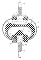
- references 1 and 1 ′ denote the semi-cylindrical sections together constituting the main composite spring with low radial stiffness.
- This spring as well as the secondary and tubular spring 2, located inside the previous one, can be made of any suitable polymerized synthetic resin, reinforced with glass fibers or the like.
- the ends 5, 5 'of the main spring 1, 1' and the ends 6 'of the secondary spring 2 are respectively anchored in blocks of elastic material (elastomer) 12, 12' bonded between the flanges 11 of a fixing stud 4 (equipped with a screw 13) and the flanges 11 'of a fixing stud 4' (equipped with a screw 13 ').
- the pad 4 ′ is adhered to a block of elastic material 3 constituting a compression stop. In fact, when the vertical forces exerted on the vibrating installation tend to bring the fixing means 4, 4 'too close together, the upper internal surface of the second spring 2 comes to crush the stop 3.
- the vertical spacing movements are limited as for them by a layer of elastic material 8 occupying part of the space 7 formed between the two springs, and adhered externally to the second spring 2, in extension of the stop 3 and of the 'anchor 12'. Indeed, when a significant tensile force is exerted on the screw 13, the internal wall of the spring 1, 1 'comes to bear progressively on the external surface of the layer 8, on both sides of the latter, which limits the vertical displacements of spacing between the screws 13 and 13', and also their relative radial displacements.
Landscapes
- Engineering & Computer Science (AREA)
- General Engineering & Computer Science (AREA)
- Mechanical Engineering (AREA)
- Health & Medical Sciences (AREA)
- Child & Adolescent Psychology (AREA)
- Springs (AREA)
- Vehicle Body Suspensions (AREA)
Description
- La présente invention concerne un dispositif élastique composite pour suspension d'installation vibrante, pourvu de moyens de fixation, d'une part à une installation vibrante telle qu'un moteur à combustion interne, d'autre part à un support fixe tel qu'un châssis de véhicule, comportant un ressort composite principal courbé à faible raideur radiale, reliant l'un à l'autre lesdits moyens de fixation en délimitant entre eux un espace de forme générale tubulaire. Un tel dispositif est déjà connu par le document EP-A-0 324 693 au nom de la demanderesse.
- Le but de l'invention est notamment d'obtenir commodément des butées en compression et en traction, ainsi qu'une limitation des déplacements radiaux relatifs entre lesdits moyens de fixation, au moins selon une direction transversale.
- A cet effet, un dispositif de suspension du type général défini au début est caractérisé en ce que ledit ressort composite secondaire est constitué d'une portion de tube échancrée dont les bords longitudinaux opposés - s'étendant selon des génératrices - sont ancrés tous deux dans l'un desdits moyens de fixation.
- Un tel dispositif peut encore se caractériser en ce que sur celui desdits moyens dans lequel est ancré ledit second ressort composite est adhérisée une butée de compression en matériau élastique.
- Lorsque ladite couche de matériau élastique est adhérisée sur la surface extérieure dudit second ressort, on peut prévoir que cette couche comporte deux surépaisseurs constituant des butées propres à coopérer avec des surfaces d'appui du moyen de fixation concerné dudit ressort composite principal.
- Avantageusement aussi, lesdits moyens de fixation peuvent être constitués chacun d'un plot comportant deux flasques entre lesquels est adhérisé du matériau élastique servant d'ancrage aux extrémités correspondantes desdits ressorts, auquel cas ledit matériau élastique servant d'ancrage peut constituer les extrémités de ladite couche.
- Sur la figure unique du dessin annexé, qui montre à titre d'exemple un mode de réalisation, en coupe transversale, les références 1 et 1' désignent les sections semicylindriques constituant ensemble le ressort composite principal à faible raideur radiale. Ce ressort, ainsi que le ressort secondaire et tubulaire 2, situé à l'intérieur du précédent, peuvent être en toute résine synthétique polymérisée appropriée, armée de fibres de verre ou analogues. Les extrémités 5, 5' du ressort principal 1, 1' et les extrémités 6' du ressort secondaire 2 sont ancrées respectivement dans des blocs de matériau élastique (élastomère) 12, 12' adhérisés entre les flasques 11 d'un plot de fixation 4 (équipé d'une vis 13) et les flasques 11' d'un plot de fixation 4' (équipé d'une vis 13').
- Au plot 4' est adhérisé un bloc de matériau élastique 3 constituant une butée de compression. En effet, lorsque les efforts verticaux s'exerçant sur l'installation vibrante tendent à rapprocher excessivement les moyens de fixation 4, 4', la surface interne supérieure du second ressort 2 vient écraser la butée 3.
- Les déplacements verticaux d'écartement sont limités quant à eux par une couche de matériau élastique 8 occupant une partie de l'espace 7 ménagé entre les deux ressorts, et adhérisée extérieurement sur le second ressort 2, en prolongation de la butée 3 et de l'ancrage 12'. En effet, lorsqu'un effort de traction important s'exerce sur la vis 13, la paroi interne du ressort 1, 1' vient progressivement en appui sur la surface externe de la couche 8, des deux côtés de celle-ci, ce qui limite les déplacements verticaux d'écartement entre les vis 13 et 13', et également leurs déplacements radiaux relatifs.
- En compression, les déplacements radiaux sont limités quant à eux par la coopération de surfaces d'appui inclinées 10 du plot 4 avec des surépaisseurs 9 de la couche 8.
Claims (5)
- Dispositif élastique composite pour suspension d'installation vibrante, pourvu de moyens de fixation, d'une part à une installation vibrante telle qu'un moteur à combustion interne, d'autre part à un support fixe tel qu'un châssis de véhicule, du type comportant un ressort composite principal courbé (1, 1') à faible raideur radiale, reliant l'un à l'autre lesdits moyens de fixation (4, 4') en délimitant entre eux un espace de forme générale tubulaire, caractérisé en ce que ledit dispositif comporte en outre un ressort composite secondaire tubulaire (2) disposé à l'intérieur dudit espace en étant fixé à l'un (4') desdits moyens de fixation, ce ressort secondaire (2) servant de butée de compression et de traction pour ledit ressort principal (1, 1'), ainsi qu'à limiter les déplacements radiaux de ce dernier, dus aux mouvements relatifs desdits moyens (4, 4'), et en ce que ledit ressort composite secondaire (2) est constitué d'une portion de tube échancrée dont les bords longitudinaux (6') opposés - s étendant selon des génératrices - sont ancrés tous deux dans l'un (4') desdits moyens de fixation.
- Dispositif selon la revendication 1, caractérisé en ce que sur celui (4') desdits moyens dans lequel est ancré ledit second ressort composite (2) est adhérisée une butée de compression (3) en matériau élastique.
- Dispositif selon la revendication 1 ou 2, dans lequel ladite couche (8) de matériau élastique est adhérisée sur la surface extérieure dudit second ressort (2), caractérisé en ce que cette couche (8) comporte deux surépaisseurs (9) constituant des butées propres à coopérer avec des surfaces d'appui (10) du moyen de fixation (4) concerné dudit ressort composite principal (1, 1').
- Dispositif selon l'une quelconque des revendications précédentes, caractérisé en ce que lesdits moyens (4, 4') de fixation sont constitués chacun d'un plot comportant deux flasques (11, 11') entre lesquels est adhérisé du matériau élastique servant d'ancrage (12, 12') aux extrémités correspondantes desdits ressorts (1, 1'-2).
- Dispositif selon les revendications 3 et 4, caractérisé en ce que ledit matériau élastique servant d'ancrage (12, 12') constitue les extrémités de ladite couche (8).
Applications Claiming Priority (2)
| Application Number | Priority Date | Filing Date | Title |
|---|---|---|---|
| FR9107972 | 1991-06-27 | ||
| FR9107972A FR2678336A1 (fr) | 1991-06-27 | 1991-06-27 | Dispositif elastique composite pour suspension d'installation vibrante. |
Publications (2)
| Publication Number | Publication Date |
|---|---|
| EP0520875A1 EP0520875A1 (fr) | 1992-12-30 |
| EP0520875B1 true EP0520875B1 (fr) | 1995-03-15 |
Family
ID=9414384
Family Applications (1)
| Application Number | Title | Priority Date | Filing Date |
|---|---|---|---|
| EP19920401755 Expired - Lifetime EP0520875B1 (fr) | 1991-06-27 | 1992-06-23 | Dispositif élastique composite pour suspension d'installation vibrante |
Country Status (4)
| Country | Link |
|---|---|
| EP (1) | EP0520875B1 (fr) |
| DE (1) | DE69201682T2 (fr) |
| ES (1) | ES2071456T3 (fr) |
| FR (1) | FR2678336A1 (fr) |
Families Citing this family (6)
| Publication number | Priority date | Publication date | Assignee | Title |
|---|---|---|---|---|
| FR2708693B1 (fr) * | 1993-08-06 | 1995-10-27 | Peugeot | Support hydroélastique pour la suspension d'un groupe motopropulseur dans la caisse d'un véhicule automobile et dispositif de suspension intégrant un tel support. |
| EP1173691B1 (fr) * | 2000-02-23 | 2004-10-13 | WOCO AVS GmbH | Palier hydraulique |
| DE10339168A1 (de) | 2003-08-21 | 2005-04-28 | Kabelschlepp Gmbh | Kettenlasche für eine Energieführungskette sowie Energieführungskette |
| DE202007018895U1 (de) * | 2007-09-12 | 2009-09-03 | Krämer, Albert | Vorrichtung zur Dämpfung von Schwingungen sowie Verwendungen der Vorrichtung |
| FR3024125B1 (fr) * | 2014-07-23 | 2017-12-22 | Airbus Operations Sas | Moyen ameliore de transmission d'efforts, agence entre un moteur d'aeronef et son mat d'accrochage |
| JP6704812B2 (ja) * | 2016-07-27 | 2020-06-03 | 株式会社ブリヂストン | 防振装置 |
Family Cites Families (5)
| Publication number | Priority date | Publication date | Assignee | Title |
|---|---|---|---|---|
| DE1260884B (de) * | 1965-01-28 | 1968-02-08 | Phoenix Gummiwerke Ag | Hohlkegelfoermiger Puffer, insbesondere fuer Krananlagen |
| FR2451511A1 (fr) * | 1979-03-12 | 1980-10-10 | Eurovib Grpt Interet Eco | Dispositif de suspension |
| US4736932A (en) * | 1985-06-18 | 1988-04-12 | The United States Of America As Represented By The Administrator Of The National Aeronautics And Space Administration | Segmented tubular cushion springs and spring assembly |
| FR2631668B2 (fr) * | 1988-01-15 | 1993-11-12 | Hutchinson | Supports elastiques de suspension |
| DE3908474A1 (de) * | 1988-07-22 | 1990-01-25 | Metzeler Gmbh | Ringfoermiger federkoerper aus faserverbundwerkstoffen |
-
1991
- 1991-06-27 FR FR9107972A patent/FR2678336A1/fr active Granted
-
1992
- 1992-06-23 EP EP19920401755 patent/EP0520875B1/fr not_active Expired - Lifetime
- 1992-06-23 DE DE1992601682 patent/DE69201682T2/de not_active Expired - Fee Related
- 1992-06-23 ES ES92401755T patent/ES2071456T3/es not_active Expired - Lifetime
Also Published As
| Publication number | Publication date |
|---|---|
| FR2678336A1 (fr) | 1992-12-31 |
| DE69201682D1 (de) | 1995-04-20 |
| DE69201682T2 (de) | 1995-07-06 |
| EP0520875A1 (fr) | 1992-12-30 |
| FR2678336B1 (fr) | 1995-02-17 |
| ES2071456T3 (es) | 1995-06-16 |
Similar Documents
| Publication | Publication Date | Title |
|---|---|---|
| FR2775583A1 (fr) | Systeme pour l'osteosynthese du rachis avec ligament | |
| FR2532600A1 (fr) | Pare-chocs pour un vehicule | |
| EP1837533B1 (fr) | Biellette de reprise de couple pourvue d'une articulation élastique | |
| EP0314539B1 (fr) | Cale élastique à rigidité bloquée dans une direction par la tension d'un câble noyé dans l'élastomère | |
| EP0520875A1 (fr) | Dispositif élastique composite pour suspension d'installation vibrante | |
| EP0018907A1 (fr) | Réservoir avec des moyens de mise en communication avec un autre réservoir ou une tubulure rigide | |
| FR2777613A1 (fr) | Manchon elastique a deux armatures; bielette de reprise de couple equipee d'un tel manchon | |
| FR2666055A1 (fr) | Support d'appui. | |
| CA2266653C (fr) | Accouplement de transmission | |
| EP0418134B1 (fr) | Support élastique, en particulier pour moteur de véhicule | |
| EP1043514B1 (fr) | Dispositif antivibratoire de reprise de couple | |
| EP1169206B1 (fr) | Dispositif d'accouplement pour wagons de chemins de fer | |
| WO1999044526A1 (fr) | Organe d'osteosynthese rachidien pour la fixation d'un ligament | |
| EP0738479A1 (fr) | Chaussure avec contrÔle de flexion de la tige | |
| EP4285036B1 (fr) | Boîtier d'actionneur électromécanique de frein à disque comportant un element amortisseur | |
| EP1155894A1 (fr) | Support antivibratoire, et véhicule comportant un tel support | |
| EP0319419B1 (fr) | Articulation flexible pour ligne d'ancrage de plate-forme pétrolière du type dit à lignes tendues | |
| EP0867316A1 (fr) | Dispositif de fixation de l'extrémité supérieure d'une jambe de suspension sur la caisse d'un véhicule | |
| FR3057237B1 (fr) | Cale allegee pour groupe motopropulseur apte a limiter des efforts verticaux | |
| FR2701752A1 (fr) | Dispositif pour relier par articulation des organes d'une ligne d'échappement, par exemple d'un véhicule automobile. | |
| FR2716687A1 (fr) | Perfectionnements aux joints de chaussée. | |
| EP0520881B1 (fr) | Bras de suspension d'organe vibrant, en particulier de moteur à combustion interne pour véhicule | |
| FR2587950A1 (fr) | Support de moteur a proprietes d'amortissement ameliorees et a faible encombrement | |
| EP3523151B1 (fr) | Cale allegee pour groupe motopropulseur apte a limiter des efforts transversaux | |
| FR2857270A1 (fr) | Dispositif d'accrochage d'une ligne de vie sous forme d'un cable |
Legal Events
| Date | Code | Title | Description |
|---|---|---|---|
| PUAI | Public reference made under article 153(3) epc to a published international application that has entered the european phase |
Free format text: ORIGINAL CODE: 0009012 |
|
| AK | Designated contracting states |
Kind code of ref document: A1 Designated state(s): BE DE ES GB IT LU NL SE |
|
| 17P | Request for examination filed |
Effective date: 19930107 |
|
| 17Q | First examination report despatched |
Effective date: 19940311 |
|
| GRAA | (expected) grant |
Free format text: ORIGINAL CODE: 0009210 |
|
| AK | Designated contracting states |
Kind code of ref document: B1 Designated state(s): BE DE ES GB IT LU NL SE |
|
| PG25 | Lapsed in a contracting state [announced via postgrant information from national office to epo] |
Ref country code: NL Free format text: LAPSE BECAUSE OF FAILURE TO SUBMIT A TRANSLATION OF THE DESCRIPTION OR TO PAY THE FEE WITHIN THE PRESCRIBED TIME-LIMIT Effective date: 19950315 |
|
| GBT | Gb: translation of ep patent filed (gb section 77(6)(a)/1977) |
Effective date: 19950313 |
|
| REF | Corresponds to: |
Ref document number: 69201682 Country of ref document: DE Date of ref document: 19950420 |
|
| ITF | It: translation for a ep patent filed | ||
| PG25 | Lapsed in a contracting state [announced via postgrant information from national office to epo] |
Ref country code: SE Effective date: 19950615 |
|
| REG | Reference to a national code |
Ref country code: ES Ref legal event code: FG2A Ref document number: 2071456 Country of ref document: ES Kind code of ref document: T3 |
|
| PG25 | Lapsed in a contracting state [announced via postgrant information from national office to epo] |
Ref country code: LU Free format text: LAPSE BECAUSE OF NON-PAYMENT OF DUE FEES Effective date: 19950630 Ref country code: BE Effective date: 19950630 |
|
| NLV1 | Nl: lapsed or annulled due to failure to fulfill the requirements of art. 29p and 29m of the patents act | ||
| BERE | Be: lapsed |
Owner name: S.A. HUTCHINSON Effective date: 19950630 |
|
| PLBE | No opposition filed within time limit |
Free format text: ORIGINAL CODE: 0009261 |
|
| STAA | Information on the status of an ep patent application or granted ep patent |
Free format text: STATUS: NO OPPOSITION FILED WITHIN TIME LIMIT |
|
| 26N | No opposition filed | ||
| PGFP | Annual fee paid to national office [announced via postgrant information from national office to epo] |
Ref country code: ES Payment date: 20000525 Year of fee payment: 9 |
|
| PGFP | Annual fee paid to national office [announced via postgrant information from national office to epo] |
Ref country code: GB Payment date: 20000616 Year of fee payment: 9 |
|
| PGFP | Annual fee paid to national office [announced via postgrant information from national office to epo] |
Ref country code: DE Payment date: 20000617 Year of fee payment: 9 |
|
| PG25 | Lapsed in a contracting state [announced via postgrant information from national office to epo] |
Ref country code: GB Free format text: LAPSE BECAUSE OF NON-PAYMENT OF DUE FEES Effective date: 20010623 |
|
| PG25 | Lapsed in a contracting state [announced via postgrant information from national office to epo] |
Ref country code: ES Free format text: LAPSE BECAUSE OF NON-PAYMENT OF DUE FEES Effective date: 20010625 |
|
| GBPC | Gb: european patent ceased through non-payment of renewal fee |
Effective date: 20010623 |
|
| PG25 | Lapsed in a contracting state [announced via postgrant information from national office to epo] |
Ref country code: DE Free format text: LAPSE BECAUSE OF NON-PAYMENT OF DUE FEES Effective date: 20020403 |
|
| REG | Reference to a national code |
Ref country code: ES Ref legal event code: FD2A Effective date: 20030203 |
|
| PG25 | Lapsed in a contracting state [announced via postgrant information from national office to epo] |
Ref country code: IT Free format text: LAPSE BECAUSE OF NON-PAYMENT OF DUE FEES;WARNING: LAPSES OF ITALIAN PATENTS WITH EFFECTIVE DATE BEFORE 2007 MAY HAVE OCCURRED AT ANY TIME BEFORE 2007. THE CORRECT EFFECTIVE DATE MAY BE DIFFERENT FROM THE ONE RECORDED. Effective date: 20050623 |