EP0520833B1 - Laminar burning internal combustion engine with fuel injection time controlling function - Google Patents
Laminar burning internal combustion engine with fuel injection time controlling function Download PDFInfo
- Publication number
- EP0520833B1 EP0520833B1 EP92305969A EP92305969A EP0520833B1 EP 0520833 B1 EP0520833 B1 EP 0520833B1 EP 92305969 A EP92305969 A EP 92305969A EP 92305969 A EP92305969 A EP 92305969A EP 0520833 B1 EP0520833 B1 EP 0520833B1
- Authority
- EP
- European Patent Office
- Prior art keywords
- fuel injection
- time
- internal combustion
- combustion engine
- injection end
- Prior art date
- Legal status (The legal status is an assumption and is not a legal conclusion. Google has not performed a legal analysis and makes no representation as to the accuracy of the status listed.)
- Expired - Lifetime
Links
Images


Classifications
-
- F—MECHANICAL ENGINEERING; LIGHTING; HEATING; WEAPONS; BLASTING
- F02—COMBUSTION ENGINES; HOT-GAS OR COMBUSTION-PRODUCT ENGINE PLANTS
- F02D—CONTROLLING COMBUSTION ENGINES
- F02D41/00—Electrical control of supply of combustible mixture or its constituents
- F02D41/0002—Controlling intake air
-
- F—MECHANICAL ENGINEERING; LIGHTING; HEATING; WEAPONS; BLASTING
- F02—COMBUSTION ENGINES; HOT-GAS OR COMBUSTION-PRODUCT ENGINE PLANTS
- F02B—INTERNAL-COMBUSTION PISTON ENGINES; COMBUSTION ENGINES IN GENERAL
- F02B27/00—Use of kinetic or wave energy of charge in induction systems, or of combustion residues in exhaust systems, for improving quantity of charge or for increasing removal of combustion residues
-
- F—MECHANICAL ENGINEERING; LIGHTING; HEATING; WEAPONS; BLASTING
- F02—COMBUSTION ENGINES; HOT-GAS OR COMBUSTION-PRODUCT ENGINE PLANTS
- F02D—CONTROLLING COMBUSTION ENGINES
- F02D41/00—Electrical control of supply of combustible mixture or its constituents
- F02D41/30—Controlling fuel injection
- F02D41/32—Controlling fuel injection of the low pressure type
- F02D41/34—Controlling fuel injection of the low pressure type with means for controlling injection timing or duration
- F02D41/345—Controlling injection timing
-
- Y—GENERAL TAGGING OF NEW TECHNOLOGICAL DEVELOPMENTS; GENERAL TAGGING OF CROSS-SECTIONAL TECHNOLOGIES SPANNING OVER SEVERAL SECTIONS OF THE IPC; TECHNICAL SUBJECTS COVERED BY FORMER USPC CROSS-REFERENCE ART COLLECTIONS [XRACs] AND DIGESTS
- Y02—TECHNOLOGIES OR APPLICATIONS FOR MITIGATION OR ADAPTATION AGAINST CLIMATE CHANGE
- Y02T—CLIMATE CHANGE MITIGATION TECHNOLOGIES RELATED TO TRANSPORTATION
- Y02T10/00—Road transport of goods or passengers
- Y02T10/10—Internal combustion engine [ICE] based vehicles
- Y02T10/40—Engine management systems
Definitions
- This invention relates to a laminar burning internal combustion engine wherein air fuel mixture and air are introduced from intake air ports into a combustion chamber such that they may make laminar tumble swirls in the combustion chamber to effect combustion of the air fuel mixture, and more particularly to a laminar burning internal combustion engine with a fuel injection time controlling function wherein the fuel injection end time is set differently depending upon whether or not the operating condition of the engine is in the proximity of a full load. operation.
- FIG. 7 schematically shows structure of a cylinder of an internal combustion engine adapted to produce such tumble swirls Fa and Fm.
- reference numeral 22 denotes a cylinder block, 24 a cylinder bore, 26 a piston, 28 a cylinder head and 30 a combustion chamber.
- a pentagonal roof 34 is formed at an upper wall of the combustion chamber 30, and a pair of intake ports 40 and 42 for intake air passageways are provided for each cylinder.
- An intake valve not shown is provided for each of the intake ports 40 and 42.
- An injector 66 is disposed in the proximity of the intake port 42 such that fuel injected from the injector 66 may be mixed into an air flow from the intake port 42 to make air fuel mixture, which is advanced into the combustion chamber 30.
- the pentagonal roof 34 has such inclined faces that can guide air and air fuel mixture from the intake ports 40 and 42 downwardly along an inner wall face of the cylinder bore 24 on extension lines of axial lines of the intake ports 40 and 42.
- the fuel air mixture is likely burnt completely.
- the air fuel ratio of the entire air and air fuel mixture is higher than the stoichiometric air fuel ratio, in short, even if the air fuel mixture as a whole is lean, the air fuel mixture can be burnt. Consequently, not only the fuel cost of the engine can be enhanced, but also reduction of hazardous exhaust substances such as CO or NOx contained in exhaust gas of the engine and prevention of knocking of the engine can be achieved.
- EP-A-0,390,589 discloses a laminar burning internal combustion engine which promotes laminar tumble swirls in the combustion chamber (See Fig. 5). It also includes fuel injector time setting means for setting a fuel injection end time to always occur during the intake stroke, a fuel injection duration time and a fuel injection start time.
- An air flow sensor is used to gauge the amount of air entering the combustion chamber. Since the amount of air entering the combustion chamber is a direct function of throttle position or load, the air sensor may be interpreted as a judging means for determining full or partial load (See col. 6, lines 32-58). No means are provided for reducing smoke on full load conditions.
- laminar burning internal combustion engine as described above is disadvantageous in that, when the air fuel ratio becomes rich upon high load operation or the like, smoke is produced in the exhaust gas.
- the disadvantage is liable to take place particularly when fuel is injected from only one of a pair of intake ports of an internal combustion engine of the two intake valve type.
- a laminar burning internal combustion engine with a fuel injection time controlling function wherein two intake ports are provided for each of a plurality of cylinders of the internal combustion engine and an injector which is controlled to be opened at a predetermined time is provided for one of the intake ports such that air fuel mixture and air are flowed from the intake ports into the combustion chamber so as to form laminar tumble swirls in the combustion chamber to effect combustion of the air fuel mixture, comprising fuel injection time setting means for setting a fuel injection end time and setting a fuel injection start time from the thus set fuel injection end time and a required fuel amount, injector driving means for driving the injector in accordance with the fuel injection times set by the fuel injection time setting means, and judging means for judging whether or not the operation condition of the internal combustion engine is in the proximity of a full load operation, the fuel injection time setting means comprising partial load time setting means for setting a partial-load fuel injection end time when it is judged by the judging means that the operation condition of the
- the fuel injection time setting means sets a fuel injection end time and sets a fuel injection start time from the thus set fuel injection end time and a required fuel amount
- the injector driving means drives the injector in accordance with the fuel injection times thus set so that fuel is injected from the injector. Consequently, air fuel mixture and air from the intake ports are flowed into the combustion chamber such that they may make laminar tumble swirls so as to effect laminar combustion in which the air fuel mixture is burnt in a laminar condition.
- the partial load time setting means sets a partial-load-time fuel injection end time, but on the contrary if it is judged by the judging means that the operation condition of the internal combustion engine is in the proximity of the full load operation, then the full load time setting means sets a full-load-time fuel injection end time. Then.
- the full load time setting means sets the full-load-time fuel injection end time to a predetermined time after starting of an intake stroke so as to reduce production of smoke and the injector is driven in accordance with the full-load-time fuel injection end time thus set, production of smoke in exhaust gas when the internal combustion engine is in the proximity of the full load operation is reduced.
- the fully open time setting means of the full-load-time fuel injection time setting means sets a fuel injection end time, when it is judged by the judging means that the operation condition of the internal combustion engine is in the proximity of the full load operation, to a predetermined time within a range from a crank angle of 60° or so after the piston top dead center upon starting of an intake stroke to another crank angle of 120° or so after the piston top dead center.
- the full load time setting means of the fuel injection time setting means is set by the full load time setting means of the fuel injection time setting means to the predetermined time within the range from the crank angle of 60° or so after the piston top dead center upon starting of an intake stroke to the crank angle of 120° or so after the piston top dead center, production of smoke is reduced with higher certainty.
- the partial load time setting means of the partial-load-time fuel injection time setting means sets a fuel injection end time for a partial load operation condition, when it is judged by the judging means that the operation condition of the internal combustion engine is not in the proximity of the full load operation, to a predetermined time within another range from a crank angle of 60° or so before the piston top dead center upon starting of an intake stroke to another crank angle of 100° or so after the piston top dead center.
- the partial-load-time fuel injection end time for a partial load operation condition when the operation condition of the internal combustion engine is not in the proximity of the full load operation is set by the partial load time setting means of the fuel injection time setting means to the predetermined time within the range from the crank angle of 60° or so before the piston top dead center upon starting of an intake stroke to the crank angle of 100° or so after the piston top dead center, combustion upon partial load operation of the internal combustion engine takes place in a good condition.
- a partial-load-time fuel injection end time set by the partial load time setting means of the fuel injection time setting means is set to on a side advanced in crank angle relative to another fuel injection end time set by the full load time setting means.
- a fuel injection end time set by the full load time setting means of the fuel injection time setting means is a predetermined time within a range from a crank angle of 60° or so after the piston top dead center upon starting of an intake stroke to another crank angle of 120° or so after the piston top dead center
- another fuel injection end time set by the partial load time setting means is a predetermined time within another range from a crank angle of 60° or so before the piston top dead center upon starting of the intake stroke to another crank angle of 100° or so after the piston top dead center.
- FIG. 1 there is provided a combustion chamber of one of cylinders and associated element of a laminar burning internal combustion engine to which the present invention is applied.
- the laminar burning internal combustion engine is provided, for example, on an automobile not shown, and each cylinder thereof has general structure substantially similar, for example, to that shown in FIG. 7. Thus, portions which are not shown in FIG. 1 will be described with reference to FIG. 7.
- each cylinder of the internal combustion engine has a combustion chamber 30 defined by a cylinder bore 24 formed in a cylinder block 22, a piston 26 and a cylinder head 28.
- Intake ports 40 and 42 extend into the combustion chamber 30, and intake valves 56 and 58 are provided in the intake ports 40 and 42, respectively.
- Reference numeral 60 denotes an exhaust valve, and 62 an exhaust port.
- a pentagonal roof 34 (refer to FIG. 7) has such inclined faces that can guide air and air fuel mixture from the intake ports 40 and 42 downwardly along an inner wall face of the cylinder bore 24 on extension lines of axial lines of the intake ports 40 and 42, respectively.
- An injector 66 is provided only for the intake port 42 as shown in FIG. 1, and an ignition plug 70 is disposed in the proximity of the intake port 42 which is thus provided with the injector 66. Consequently, fuel injected from the injector 66 is mixed into an air flow from the intake port 42 to make air fuel mixture, which is advanced into the combustion chamber 30.
- the injector 66 is driven by an injector driver (injector driving means) 72.
- the injector driver 72 drives the injector 66 in accordance with a fuel injection time which is set by fuel injection time setting means 74.
- the fuel injection time setting means 74 is provided, for example, in an electronic control unit (ECU) 80 which executes various controls of the engine such as control of an ignition timing.
- the fuel injection time setting means 74 thus sets a fuel injection end time and further sets a fuel injection start time in accordance with the thus set fuel injection end time and a required fuel amount.
- the required fuel amount is an amount of fuel to be injected from the injector 66 in each combustion cycle, and it can be adjusted by a driving time of the injector 66 (valve opening time). Then, the valve opening time of the injector 66 is calculated from an engine speed Ne and an intake air amount. To this end, detection information from an engine speed sensor (not shown) and an intake air amount sensor (air flow sensor) (not shown) are transmitted to the ECU 80.
- the fuel injection time setting means 74 calculates a basic driving time of the injector 66 from the engine speed Ne and the intake air amount and corrects the thus calculated basic driving time in accordance with a temperature of cooling water including such an increasing correction when the engine is in a cold condition (water temperature increasing correction), an increasing correction upon and after starting of the engine or an increasing correction after idling to determine a driving time of the injector 66. Then, the fuel injection time setting means 74 converts the thus determined driving time of the injector 66 into a crank angle.
- the fuel injection time setting means 74 reads one of preset fuel injection end times stored in a ROM (not shown) of the ECU 80 to set a fuel injection end time and then reversely calculates a fuel injection start time from the thus set fuel injection end time and the injector driving time after conversion into the crank angle. In short, a point of time prior to the fuel injection end time by the injector driving time is set as a fuel injection start time.
- Two different values are set for each fuel injection end time in the ROM of the ECU 80 including a fuel injection end time for normal operation, that is, for partial load operation of the engine and another fuel injection end time for full load operation or operation in the proximity of the full load operation of the engine.
- the fuel injection end time for partial load operation is set to a point of time within a range from a crank angle of 60° or so before the top dead center of the piston upon starting of an intake stroke (60° BTDC) to another crank angle of 100° or so after the top dead center (100° ATDC), for example, to a point of time at which combustion takes place completely.
- the fuel injection end time for full load operation is set to a point of time within another range from a crank angle of 60° or so after the top dead center of the piston upon starting of an intake stroke (60° ATDC) to another crank angle of 120° or so after the top dead center (120° ATDC), for example, to a point of time at which production of smoke in exhaust gas is reduced.
- the fuel injection end time for partial load operation is set to 40° or so after the piston top dead center (40° ATDC), and a fuel injection end time for full load operation is set to 120° or so after the piston top dead center (120° ATDC).
- the fuel injection end time for partial load operation should preferably be retarded further than 40° after the piston top dead center.
- the reason why nevertheless the fuel injection end time for partial load operation is set to that value is that, if the fuel injection end time is early in this manner, then a rise in pressure and temperature upon combustion can be reduced so that production of NOx ca be reduced remarkably.
- the value of 40° after the piston top dead center to which the fuel injection end time for partial load operation is set is sufficiently effective for an effect of lean combustion, in short, for a fuel cost reducing effect.
- the effect of lean combustion can be enhanced if the fuel injection end time is retarded further than 40° after the piston top dead center.
- describing a relationship between the fuel injection end time for partial load operation and the fuel injection end time for full load operation if reduction of NOx in exhaust gas is considered, then it has been confirmed by experiments that preferably the fuel injection end time upon partial load operation is earlier than the fuel injection end time upon fully open operation.
- the fuel injection end time for partial load operation is determined taking an effect of lean combustion into consideration and further, if necessary, taking reduction of NOx into consideration, and the fuel injection end time for full load operation is determined taking reduction of smoke into consideration.
- Judgment whether the operation condition of the engine is a partial load operation or a full load operation is performed by judging means 76 provided in the ECU 80.
- the judging means 76 judges that, if, for example, a current volumetric efficiency is within a full load operation zone (WOT zone) in which the volumetric efficiency is higher than a predetermined volumetric efficiency ⁇ v ( ⁇ v is a fixed value) in the proximity of the full load volumetric efficiency (WOT) as shown in FIG. 2, then the engine is in a fully open operation condition, but if the current volumetric efficiency is not within the WOT zone, then the judging means 76 judges that the engine is operating in a partial load operation condition.
- a volumetric efficiency can be calculated from an intake air amount or the like.
- the laminar burning internal combustion engine with a fuel injection time controlling function of the embodiment of the present invention is constructed in such a manner as described above, flows of air and air fuel mixture from the intake ports 40 and 42 form such laminar tumble swirls as indicated by the arrow marks Fa and Fm, respectively, (refer to FIG. 7) in the combustion chamber 30, which promotes complete combustion of the air fuel mixture.
- the air fuel ratio of the entire air and air fuel mixture is higher than the stoichiometric air fuel ratio (in short, even if the air fuel mixture as a whole is lean). combustion of the air fuel mixture is permitted, which improves the fuel mileage of the engine and besides achieves reduction of hazardous exhaust substances such as CO and NOx contained in exhaust gas of the engine and prevention of knocking of the engine.
- the fuel injection time setting means 74 sets, upon partial load operation wherein the operation of the engine is not in the proximity of the full load operation, the fuel injection end time (partial injection end time) to a point of time at which combustion is performed completely so as to enhance the efficiency of the engine, the effects described above can be achieved with certainty.
- the fuel injection time setting means 74 sets, when the air fuel ratio becomes rich upon high load operation or the like, the fuel injection end time such that smoke may not be produced in exhaust gas and then fuel injection is performed in accordance with the thus set air fuel ratio, smoke is not likely produced in exhaust gas.
- the judging means 76 of the fuel injection time setting means 74 judges from a volumetric efficiency whether or not the engine is in the WOT zone (in the full load operation condition). If the engine is in the WOT zone, then the fuel injection setting means 74 sets a WOT injection end time (for example, 120° ATDC) as a fuel injection end time at step a2, but on the contrary if the engine is not in the WOT zone, then the fuel injection setting means 74 sets a partial injection end time (for example, 40° ATDC) as a fuel injection end time at step a3.
- a WOT injection end time for example, 120° ATDC
- a partial injection end time for example, 40° ATDC
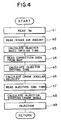
- fuel injection time control is executed, for example, as illustrated in FIG. 4.
- an engine speed Ne is read in first at step bl, and then an intake air amount is read in at step b2, whereafter a basic driving time of the injector 66 is calculated at step b3.
- correction data are read in from a map (MAP) at step b4, and using the correction data, a correction of the basic driving time such as a water temperature increasing correction, an increasing correction upon or after starting or an increasing correction after idling is performed at step b5.
- a correction of the basic driving time such as a water temperature increasing correction, an increasing correction upon or after starting or an increasing correction after idling is performed at step b5.
- the driving time of the injector 66 obtained by the correction of the basic driving time is converted into a crank angle at step b6.
- a fuel injection end time set as described above in connection with the flow chart of FIG. 3 is read in at step b7, and then at step b8, a fuel injection start time is calculated reversely from the fuel injection end time by the driving time of the injector 66 after conversion into a crank angle.
- the injector 66 is driven in response to the fuel injection start time and fuel injection end time thus set to perform injection of fuel.
- the fuel injection end time in short. the WOT injection end time, when the air fuel ratio becomes rich depends upon characteristics of the internal combustion engine and is thus set to a value in accordance with the characteristics.
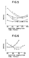
- FIGS. 5 and 6 show smoke production characteristics of certain internal combustion engines.
- ⁇ indicates data at the engine speed of 1,000 rpm; ⁇ indicates data at the engine speed of 2,000 rpm; and ⁇ indicates data at the engine speed of 3,000 rpm
- a solid line indicates a characteristic curve obtained from the data of ⁇ ;
- a broken line indicates a characteristic curve obtained from the data of ⁇ ;
- an alternate long and short dash line indicates a characteristic curve obtained from the data of ⁇ .
- the data ( ⁇ , ⁇ , ⁇ ) shown at an upper portion are data when the air fuel ratio (A/F) is 11
- the data ( ⁇ , ⁇ , ⁇ ) shown at a lower portion are data when the air fuel ratio (A/F) is 12.5.
- the data ( ⁇ , ⁇ , ⁇ ) shown in FIG. 6 are data when-the air fuel ratio (A/F) is 11.
- the internal combustion engine in the present embodiment has such characteristics as illustrated in FIG. 5. From FIG. 5, it can be seen that smoke presents its minimum when the fuel injection end time is at or around 120° ATDC. Accordingly, it can be seen that, if the fuel injection end time when the air fuel ratio becomes rich is set to a value equal to or around the 120° ATDC, then smoke in exhaust gas can be minimized.
- smoke is small in amount when the fuel injection end time is at or near 60° ATDC, and if the fuel injection end time when the air fuel ratio becomes rich is set to such time (at or around 60° ATDC), then smoke in exhaust gas can be minimized.
- the setting of a fuel injection end time for reduction of smoke may be performed based on an excess air ratio.
- a condition wherein the excess air ratio is lower than 1.0 is regarded as a rich condition, and in such rich condition, the fuel injection end time is set to a fuel injection end time for reduction of smoke.
- the WOT zone described above corresponds to a condition wherein the excess air ratio is lower than 1.0, and the volumetric efficiency ⁇ v which defines a lower limit of the WOT zone is set to a value substantially equal to 80 % of the volumetric efficiency of the WOT.
- an aimed fuel injection end time may be set to a fuel injection end time for reduction of smoke when the volumetric efficiency is within the WOT zone and the excess air ratio is lower than 1.0.
- a laminar burning internal combustion engine with a fuel injection time controlling function wherein two intake ports are provided for each of a plurality of cylinders of the internal combustion engine and an injector which is controlled to be opened at the intake stroke at the cylinder is provided for one of the intake ports such that air fuel mixture and air are flowed from the intake ports into the combustion chamber so as to form laminar tumble swirls in the combustion chamber to effect combustion of the air fuel mixture
- it comprises fuel injection time setting means for setting a fuel injection end time and setting a fuel injection start time from the thus set fuel injection end time and a required fuel amount, injector driving means for driving the injector in accordance with the fuel injection times set by the fuel injection time setting means, and judging means for judging whether or not the operation condition of the internal combustion engine is in the proximity of the full load operation
- the fuel injection time setting means comprising partial load time setting means for setting a partial-load-time fuel injection end time when it is judged by the judging means that
- the full load time setting means of the fuel injection time setting means is constructed such that it sets a fuel injection end time when it is judged by the judging means that the volumetric efficiency of the internal combustion engine is in the proximity of the full load operation to a predetermined time within a range from a crank angle of 60° or so after the piston top dead center upon starting of an intake stroke to another crank angle of 120° or so after the piston top dead center, an exhaust gas purifying effect by reduction of production of smoke is achieved with higher certainty.
- the partial load time setting means of the fuel injection time setting means is constructed such that it sets a fuel injection end time for a partial load operation condition when it is judged by the judging means that the volumetric efficiency of the internal combustion engine is not in the proximity of the full load operation to a predetermined time within another range from a crank angle of 60° or so before the piston top dead center upon starting of an intake stroke to another crank angle of 100° or so after the piston top dead center, combustion upon partial load operation of the internal combustion engine takes place in a good condition and the performance of the internal combustion engine is improved.
- a fuel injection end time set by the partial load time setting means of the fuel injection time setting means is set on a side in crank angle relative to another fuel injection end time set by the full load time setting means
- a fuel injection end time set by the full load time setting means is a predetermined time within a range from a crank angle of 60° or so after the piston top dead center upon starting of an intake stroke to another crank angle of 120° or so after the piston top dead center
- another fuel injection end time set by the partial load time setting means is a predetermined time within another range from a crank angle of 60° or so before the piston top dead center upon starting of the intake stroke to another crank angle of 100° or so after the piston top dead center
Landscapes
- Engineering & Computer Science (AREA)
- Chemical & Material Sciences (AREA)
- Combustion & Propulsion (AREA)
- Mechanical Engineering (AREA)
- General Engineering & Computer Science (AREA)
- Electrical Control Of Air Or Fuel Supplied To Internal-Combustion Engine (AREA)
Description
- This invention relates to a laminar burning internal combustion engine wherein air fuel mixture and air are introduced from intake air ports into a combustion chamber such that they may make laminar tumble swirls in the combustion chamber to effect combustion of the air fuel mixture, and more particularly to a laminar burning internal combustion engine with a fuel injection time controlling function wherein the fuel injection end time is set differently depending upon whether or not the operating condition of the engine is in the proximity of a full load. operation.
- It is effective, as means for enhancing combustion of an internal combustion engine, for example, to produce, at the intake stroke, such vertical whirling flows, i.e., so-called tumble swirls, as shown in FIG. 7 in a cylinder.
- FIG. 7 schematically shows structure of a cylinder of an internal combustion engine adapted to produce such tumble swirls Fa and Fm. Referring to FIG. 7, reference numeral 22 denotes a cylinder block, 24 a cylinder bore, 26 a piston, 28 a cylinder head and 30 a combustion chamber. A
pentagonal roof 34 is formed at an upper wall of thecombustion chamber 30, and a pair ofintake ports intake ports - An
injector 66 is disposed in the proximity of theintake port 42 such that fuel injected from theinjector 66 may be mixed into an air flow from theintake port 42 to make air fuel mixture, which is advanced into thecombustion chamber 30. - The
pentagonal roof 34 has such inclined faces that can guide air and air fuel mixture from theintake ports intake ports - Consequently, the flows of air and air fuel mixture from the
intake ports pentagonal roof 34, such laminar tumble swirls as indicated by arrow marks Fa and Fm. respectively, in thecombustion chamber 30. - As a result, the fuel air mixture is likely burnt completely. Thus, for example, even if the air fuel ratio of the entire air and air fuel mixture is higher than the stoichiometric air fuel ratio, in short, even if the air fuel mixture as a whole is lean, the air fuel mixture can be burnt. Consequently, not only the fuel cost of the engine can be enhanced, but also reduction of hazardous exhaust substances such as CO or NOx contained in exhaust gas of the engine and prevention of knocking of the engine can be achieved.
- EP-A-0,390,589 (compare with 1 part of claim 1) discloses a laminar burning internal combustion engine which promotes laminar tumble swirls in the combustion chamber (See Fig. 5). It also includes fuel injector time setting means for setting a fuel injection end time to always occur during the intake stroke, a fuel injection duration time and a fuel injection start time. An air flow sensor is used to gauge the amount of air entering the combustion chamber. Since the amount of air entering the combustion chamber is a direct function of throttle position or load, the air sensor may be interpreted as a judging means for determining full or partial load (See col. 6, lines 32-58). No means are provided for reducing smoke on full load conditions.
- However, such a laminar (also known as "stratified charge") burning internal combustion engine as described above is disadvantageous in that, when the air fuel ratio becomes rich upon high load operation or the like, smoke is produced in the exhaust gas. The disadvantage is liable to take place particularly when fuel is injected from only one of a pair of intake ports of an internal combustion engine of the two intake valve type.
- While it may seem a promising idea. as means for suppressing production of such smoke. to limit the spraying spreading angle of fuel at an injector so that fuel injected from the injector may not stick to an inner wall of an intake port, since production of smoke depends upon a burning condition of fuel in the combustion chamber, production of smoke can be reduced by a fuel injection time.
- It is an object of the present invention to provide a laminar burning internal combustion engine with a fuel injection time controlling function wherein production of smoke upon high load operation of the engine can be reduced by control of the fuel injection time.
- In order to attain the object, according to the present invention, there is provided a laminar burning internal combustion engine with a fuel injection time controlling function wherein two intake ports are provided for each of a plurality of cylinders of the internal combustion engine and an injector which is controlled to be opened at a predetermined time is provided for one of the intake ports such that air fuel mixture and air are flowed from the intake ports into the combustion chamber so as to form laminar tumble swirls in the combustion chamber to effect combustion of the air fuel mixture, comprising fuel injection time setting means for setting a fuel injection end time and setting a fuel injection start time from the thus set fuel injection end time and a required fuel amount, injector driving means for driving the injector in accordance with the fuel injection times set by the fuel injection time setting means, and judging means for judging whether or not the operation condition of the internal combustion engine is in the proximity of a full load operation, the fuel injection time setting means comprising partial load time setting means for setting a partial-load fuel injection end time when it is judged by the judging means that the operation condition of the internal combustion engine is not in the proximity of the full load operation, and full load time setting means for setting a full-load-time fuel injection end time different from the partial-load-time fuel injection end time when it is judged by the judging means that the operation condition of the internal combustion engine is in the proximity of the full load operation, the full load time setting means setting the full-load-time fuel injection end time to a predetermined time after starting of an intake stroke so as to reduce production of smoke which is liable to take place upon full load operation of the internal combustion engine.
- In the laminar burning internal combustion engine with a fuel injection time controlling function of the present invention, the fuel injection time setting means sets a fuel injection end time and sets a fuel injection start time from the thus set fuel injection end time and a required fuel amount, and the injector driving means drives the injector in accordance with the fuel injection times thus set so that fuel is injected from the injector. Consequently, air fuel mixture and air from the intake ports are flowed into the combustion chamber such that they may make laminar tumble swirls so as to effect laminar combustion in which the air fuel mixture is burnt in a laminar condition. In this instance, if it is judged by the judging means that the operation condition of the internal combustion engine is not in the proximity of the full load operation, then the partial load time setting means sets a partial-load-time fuel injection end time, but on the contrary if it is judged by the judging means that the operation condition of the internal combustion engine is in the proximity of the full load operation, then the full load time setting means sets a full-load-time fuel injection end time. Then. since the full load time setting means sets the full-load-time fuel injection end time to a predetermined time after starting of an intake stroke so as to reduce production of smoke and the injector is driven in accordance with the full-load-time fuel injection end time thus set, production of smoke in exhaust gas when the internal combustion engine is in the proximity of the full load operation is reduced.
- Preferably, the fully open time setting means of the full-load-time fuel injection time setting means sets a fuel injection end time, when it is judged by the judging means that the operation condition of the internal combustion engine is in the proximity of the full load operation, to a predetermined time within a range from a crank angle of 60° or so after the piston top dead center upon starting of an intake stroke to another crank angle of 120° or so after the piston top dead center. Since the fuel injection end time when the operation condition of the internal combustion engine is in the proximity of the full load operation is set by the full load time setting means of the fuel injection time setting means to the predetermined time within the range from the crank angle of 60° or so after the piston top dead center upon starting of an intake stroke to the crank angle of 120° or so after the piston top dead center, production of smoke is reduced with higher certainty.
- Preferably, the partial load time setting means of the partial-load-time fuel injection time setting means sets a fuel injection end time for a partial load operation condition, when it is judged by the judging means that the operation condition of the internal combustion engine is not in the proximity of the full load operation, to a predetermined time within another range from a crank angle of 60° or so before the piston top dead center upon starting of an intake stroke to another crank angle of 100° or so after the piston top dead center. Since the partial-load-time fuel injection end time for a partial load operation condition when the operation condition of the internal combustion engine is not in the proximity of the full load operation is set by the partial load time setting means of the fuel injection time setting means to the predetermined time within the range from the crank angle of 60° or so before the piston top dead center upon starting of an intake stroke to the crank angle of 100° or so after the piston top dead center, combustion upon partial load operation of the internal combustion engine takes place in a good condition.
- Preferably, a partial-load-time fuel injection end time set by the partial load time setting means of the fuel injection time setting means is set to on a side advanced in crank angle relative to another fuel injection end time set by the full load time setting means. In this instance, preferably a fuel injection end time set by the full load time setting means of the fuel injection time setting means is a predetermined time within a range from a crank angle of 60° or so after the piston top dead center upon starting of an intake stroke to another crank angle of 120° or so after the piston top dead center, and another fuel injection end time set by the partial load time setting means is a predetermined time within another range from a crank angle of 60° or so before the piston top dead center upon starting of the intake stroke to another crank angle of 100° or so after the piston top dead center. Since the fuel injection end time set by the partial load time setting means of the fuel injection time setting means is set on a side advanced in crank angle relative to the fuel injection end time set by the full load time setting means, NOx in exhaust gas upon partial load operation of the internal combustion engine is reduced.
- The above and other objects and advantages of the present invention will become apparent from the following description and the appended claims. taken in conjunction with the accompanying drawings in which like parts are denoted by like reference characters all through the drawings.
-
- FIG. 1 is a schematic plan view showing construction of a combustion chamber of a cylinder and associated elements of a laminar burning internal combustion engine with a fuel injection time controlling function to which the present invention is applied:
- FIG. 2 is a graph showing a full load operation zone of the volume efficiency of the laminar burning internal combustion engine of FIG. 1:
- FIG. 3 is a flow chart showing a flow of control for setting an injection end time in fuel injection time control of the laminar burning internal combustion engine of FIG. 1:
- FIG. 4 is a flow chart showing a flow of the fuel injection time control of the laminar burning internal combustion engine of FIG. 1:
- FIG. 5 is a graph showing an example of smoke production characteristic of the laminar burning internal combustion engine of FIG. 1;
- FIG. 6 is a graph showing another example of smoke production characteristic of the laminar burning internal combustion engine of FIG. 1; and
- FIG. 7 is a schematic perspective view illustrating production of tumble swirls in a combustion chamber of a cylinder of a laminar burning internal combustion engine.
- Referring first to FIG. 1, there is provided a combustion chamber of one of cylinders and associated element of a laminar burning internal combustion engine to which the present invention is applied. The laminar burning internal combustion engine is provided, for example, on an automobile not shown, and each cylinder thereof has general structure substantially similar, for example, to that shown in FIG. 7. Thus, portions which are not shown in FIG. 1 will be described with reference to FIG. 7.
- Thus, referring to FIGS. 1 and 7, each cylinder of the internal combustion engine has a
combustion chamber 30 defined by acylinder bore 24 formed in a cylinder block 22, apiston 26 and acylinder head 28.Intake ports combustion chamber 30, andintake valves intake ports Reference numeral 60 denotes an exhaust valve, and 62 an exhaust port. - It is to be noted that a pentagonal roof 34 (refer to FIG. 7) has such inclined faces that can guide air and air fuel mixture from the
intake ports intake ports - An
injector 66 is provided only for theintake port 42 as shown in FIG. 1, and anignition plug 70 is disposed in the proximity of theintake port 42 which is thus provided with theinjector 66. Consequently, fuel injected from theinjector 66 is mixed into an air flow from theintake port 42 to make air fuel mixture, which is advanced into thecombustion chamber 30. - The
injector 66 is driven by an injector driver (injector driving means) 72. Theinjector driver 72 drives theinjector 66 in accordance with a fuel injection time which is set by fuel injection time setting means 74. - The fuel injection time setting means 74 is provided, for example, in an electronic control unit (ECU) 80 which executes various controls of the engine such as control of an ignition timing. The fuel injection time setting means 74 thus sets a fuel injection end time and further sets a fuel injection start time in accordance with the thus set fuel injection end time and a required fuel amount.
- It is to be noted that the required fuel amount is an amount of fuel to be injected from the
injector 66 in each combustion cycle, and it can be adjusted by a driving time of the injector 66 (valve opening time). Then, the valve opening time of theinjector 66 is calculated from an engine speed Ne and an intake air amount. To this end, detection information from an engine speed sensor (not shown) and an intake air amount sensor (air flow sensor) (not shown) are transmitted to theECU 80. - Here, the fuel injection time setting means 74 calculates a basic driving time of the
injector 66 from the engine speed Ne and the intake air amount and corrects the thus calculated basic driving time in accordance with a temperature of cooling water including such an increasing correction when the engine is in a cold condition (water temperature increasing correction), an increasing correction upon and after starting of the engine or an increasing correction after idling to determine a driving time of theinjector 66. Then, the fuel injection time setting means 74 converts the thus determined driving time of theinjector 66 into a crank angle. - Further, the fuel injection time setting means 74 reads one of preset fuel injection end times stored in a ROM (not shown) of the
ECU 80 to set a fuel injection end time and then reversely calculates a fuel injection start time from the thus set fuel injection end time and the injector driving time after conversion into the crank angle. In short, a point of time prior to the fuel injection end time by the injector driving time is set as a fuel injection start time. - Two different values are set for each fuel injection end time in the ROM of the
ECU 80 including a fuel injection end time for normal operation, that is, for partial load operation of the engine and another fuel injection end time for full load operation or operation in the proximity of the full load operation of the engine. - The fuel injection end time for partial load operation is set to a point of time within a range from a crank angle of 60° or so before the top dead center of the piston upon starting of an intake stroke (60° BTDC) to another crank angle of 100° or so after the top dead center (100° ATDC), for example, to a point of time at which combustion takes place completely.
- On the other hand, the fuel injection end time for full load operation is set to a point of time within another range from a crank angle of 60° or so after the top dead center of the piston upon starting of an intake stroke (60° ATDC) to another crank angle of 120° or so after the top dead center (120° ATDC), for example, to a point of time at which production of smoke in exhaust gas is reduced.
- Here, the fuel injection end time for partial load operation is set to 40° or so after the piston top dead center (40° ATDC), and a fuel injection end time for full load operation is set to 120° or so after the piston top dead center (120° ATDC).
- It is to be noted that. if only lean combustion is considered, then the fuel injection end time for partial load operation should preferably be retarded further than 40° after the piston top dead center. The reason why nevertheless the fuel injection end time for partial load operation is set to that value is that, if the fuel injection end time is early in this manner, then a rise in pressure and temperature upon combustion can be reduced so that production of NOx ca be reduced remarkably. It is to be noted that the value of 40° after the piston top dead center to which the fuel injection end time for partial load operation is set is sufficiently effective for an effect of lean combustion, in short, for a fuel cost reducing effect.
- Further, describing the fuel injection end time for partial load operation, when the internal combustion engine is provided with an exhaust emission control apparatus such as a catalyzer for sufficiently reducing NOx in exhaust gas, the effect of lean combustion can be enhanced if the fuel injection end time is retarded further than 40° after the piston top dead center. In this connection, describing a relationship between the fuel injection end time for partial load operation and the fuel injection end time for full load operation, if reduction of NOx in exhaust gas is considered, then it has been confirmed by experiments that preferably the fuel injection end time upon partial load operation is earlier than the fuel injection end time upon fully open operation. Anyway, however. the fuel injection end time for partial load operation is determined taking an effect of lean combustion into consideration and further, if necessary, taking reduction of NOx into consideration, and the fuel injection end time for full load operation is determined taking reduction of smoke into consideration.
- Judgment whether the operation condition of the engine is a partial load operation or a full load operation is performed by judging
means 76 provided in theECU 80. The judging means 76 judges that, if, for example, a current volumetric efficiency is within a full load operation zone (WOT zone) in which the volumetric efficiency is higher than a predetermined volumetric efficiency ηv (ηv is a fixed value) in the proximity of the full load volumetric efficiency (WOT) as shown in FIG. 2, then the engine is in a fully open operation condition, but if the current volumetric efficiency is not within the WOT zone, then the judging means 76 judges that the engine is operating in a partial load operation condition. It is to be noted that a volumetric efficiency can be calculated from an intake air amount or the like. - Since the laminar burning internal combustion engine with a fuel injection time controlling function of the embodiment of the present invention is constructed in such a manner as described above, flows of air and air fuel mixture from the
intake ports combustion chamber 30, which promotes complete combustion of the air fuel mixture. Thus, even if, for example, the air fuel ratio of the entire air and air fuel mixture is higher than the stoichiometric air fuel ratio (in short, even if the air fuel mixture as a whole is lean). combustion of the air fuel mixture is permitted, which improves the fuel mileage of the engine and besides achieves reduction of hazardous exhaust substances such as CO and NOx contained in exhaust gas of the engine and prevention of knocking of the engine. - Particularly, since the fuel injection time setting means 74 sets, upon partial load operation wherein the operation of the engine is not in the proximity of the full load operation, the fuel injection end time (partial injection end time) to a point of time at which combustion is performed completely so as to enhance the efficiency of the engine, the effects described above can be achieved with certainty.
- On the other hand. since the fuel injection time setting means 74 sets, when the air fuel ratio becomes rich upon high load operation or the like, the fuel injection end time such that smoke may not be produced in exhaust gas and then fuel injection is performed in accordance with the thus set air fuel ratio, smoke is not likely produced in exhaust gas.
- In short, operation of the fuel injection time setting means 74 is illustrated in FIG. 3. Referring to FIG. 3, first at step al, the judging means 76 of the fuel injection time setting means 74 judges from a volumetric efficiency whether or not the engine is in the WOT zone (in the full load operation condition). If the engine is in the WOT zone, then the fuel injection setting means 74 sets a WOT injection end time (for example, 120° ATDC) as a fuel injection end time at step a2, but on the contrary if the engine is not in the WOT zone, then the fuel injection setting means 74 sets a partial injection end time (for example, 40° ATDC) as a fuel injection end time at step a3.
- Then, fuel injection time control is executed, for example, as illustrated in FIG. 4. Referring to FIG. 4, an engine speed Ne is read in first at step bl, and then an intake air amount is read in at step b2, whereafter a basic driving time of the
injector 66 is calculated at step b3. - Subsequently, correction data are read in from a map (MAP) at step b4, and using the correction data, a correction of the basic driving time such as a water temperature increasing correction, an increasing correction upon or after starting or an increasing correction after idling is performed at step b5.
- Further, the driving time of the
injector 66 obtained by the correction of the basic driving time is converted into a crank angle at step b6. Then, a fuel injection end time set as described above in connection with the flow chart of FIG. 3 is read in at step b7, and then at step b8, a fuel injection start time is calculated reversely from the fuel injection end time by the driving time of theinjector 66 after conversion into a crank angle. - The
injector 66 is driven in response to the fuel injection start time and fuel injection end time thus set to perform injection of fuel. - As a result, production of smoke when the air fuel ratio becomes rich such as upon high load operation of the engine is reduced, which is effective for purification of exhaust gas.
- It is to be noted that, the fuel injection end time, in short. the WOT injection end time, when the air fuel ratio becomes rich depends upon characteristics of the internal combustion engine and is thus set to a value in accordance with the characteristics.
- For example, FIGS. 5 and 6 show smoke production characteristics of certain internal combustion engines. In FIGS. 5 and 6, ○ indicates data at the engine speed of 1,000 rpm; △ indicates data at the engine speed of 2,000 rpm; and × indicates data at the engine speed of 3,000 rpm, and a solid line indicates a characteristic curve obtained from the data of ○ ; a broken line indicates a characteristic curve obtained from the data of Δ ; and an alternate long and short dash line indicates a characteristic curve obtained from the data of × . In FIG. 5, the data (○ , Δ , × ) shown at an upper portion are data when the air fuel ratio (A/F) is 11, and the data (○ , Δ , × ) shown at a lower portion are data when the air fuel ratio (A/F) is 12.5. Meanwhile, the data (○ , Δ , × ) shown in FIG. 6 are data when-the air fuel ratio (A/F) is 11.
- The internal combustion engine in the present embodiment has such characteristics as illustrated in FIG. 5. From FIG. 5, it can be seen that smoke presents its minimum when the fuel injection end time is at or around 120° ATDC. Accordingly, it can be seen that, if the fuel injection end time when the air fuel ratio becomes rich is set to a value equal to or around the 120° ATDC, then smoke in exhaust gas can be minimized.
- On the other hand, with an internal combustion engine having such characteristics as illustrated in FIG. 6, smoke is small in amount when the fuel injection end time is at or near 60° ATDC, and if the fuel injection end time when the air fuel ratio becomes rich is set to such time (at or around 60° ATDC), then smoke in exhaust gas can be minimized.
- It is to be noted that naturally it is a promising idea to provide, in addition to such control of a fuel injection end time as described above, means for reducing production of smoke by limiting the spraying spreading angle at the injector so that fuel injected from the injector may not stick to an inner wall of the intake port, and in this instance, a higher smoke reducing effect can be anticipated.
- It is to be noted that, while a fuel injection end time for reducing production of smoke is set, in the embodiment described above, when the volumetric efficiency of the engine is within the WOT zone, such setting is performed from the point of view that, when the volumetric efficiency is within the WOT zone, also the air fuel ratio of air fuel mixture becomes rich with fuel and production of smoke likely increases.
- The setting of a fuel injection end time for reduction of smoke may be performed based on an excess air ratio. For example, a condition wherein the excess air ratio is lower than 1.0 is regarded as a rich condition, and in such rich condition, the fuel injection end time is set to a fuel injection end time for reduction of smoke.
- Further, the WOT zone described above corresponds to a condition wherein the excess air ratio is lower than 1.0, and the volumetric efficiency ηv which defines a lower limit of the WOT zone is set to a value substantially equal to 80 % of the volumetric efficiency of the WOT.
- Or else, an aimed fuel injection end time may be set to a fuel injection end time for reduction of smoke when the volumetric efficiency is within the WOT zone and the excess air ratio is lower than 1.0.
- As described in detail so far, since, according to the present invention, a laminar burning internal combustion engine with a fuel injection time controlling function wherein two intake ports are provided for each of a plurality of cylinders of the internal combustion engine and an injector which is controlled to be opened at the intake stroke at the cylinder is provided for one of the intake ports such that air fuel mixture and air are flowed from the intake ports into the combustion chamber so as to form laminar tumble swirls in the combustion chamber to effect combustion of the air fuel mixture is constructed such that it comprises fuel injection time setting means for setting a fuel injection end time and setting a fuel injection start time from the thus set fuel injection end time and a required fuel amount, injector driving means for driving the injector in accordance with the fuel injection times set by the fuel injection time setting means, and judging means for judging whether or not the operation condition of the internal combustion engine is in the proximity of the full load operation, the fuel injection time setting means comprising partial load time setting means for setting a partial-load-time fuel injection end time when it is judged by the judging means that the operation condition of the internal combustion engine is not in the proximity of the full load operation, and full load time setting means for setting a fuel injection end time when it is judged by the judging means that the operation condition of the internal combustion engine is in the proximity of the full load operation, the full load time setting means setting the full-load-time fuel injection end time to a predetermined time after starting of an intake stroke so as to reduce production of smoke which is liable to take place upon full load operation of the internal combustion engine, production of smoke in exhaust gas upon high load operation of the laminar burning internal combustion engine can be reduced Consequently, an effect that exhaust gas can be purified is achieved.
- When the full load time setting means of the fuel injection time setting means is constructed such that it sets a fuel injection end time when it is judged by the judging means that the volumetric efficiency of the internal combustion engine is in the proximity of the full load operation to a predetermined time within a range from a crank angle of 60° or so after the piston top dead center upon starting of an intake stroke to another crank angle of 120° or so after the piston top dead center, an exhaust gas purifying effect by reduction of production of smoke is achieved with higher certainty.
- Further, when the partial load time setting means of the fuel injection time setting means is constructed such that it sets a fuel injection end time for a partial load operation condition when it is judged by the judging means that the volumetric efficiency of the internal combustion engine is not in the proximity of the full load operation to a predetermined time within another range from a crank angle of 60° or so before the piston top dead center upon starting of an intake stroke to another crank angle of 100° or so after the piston top dead center, combustion upon partial load operation of the internal combustion engine takes place in a good condition and the performance of the internal combustion engine is improved.
- Further, when the laminar burning internal combustion engine with a fuel injection time controlling function is constructed such that a fuel injection end time set by the partial load time setting means of the fuel injection time setting means is set on a side in crank angle relative to another fuel injection end time set by the full load time setting means, and particularly when, in this condition, a fuel injection end time set by the full load time setting means is a predetermined time within a range from a crank angle of 60° or so after the piston top dead center upon starting of an intake stroke to another crank angle of 120° or so after the piston top dead center and another fuel injection end time set by the partial load time setting means is a predetermined time within another range from a crank angle of 60° or so before the piston top dead center upon starting of the intake stroke to another crank angle of 100° or so after the piston top dead center, an exhaust gas purifying effect by suppression of production of smoke is obtained in the full load operation condition of the internal combustion engine, but in the partial load operation condition of the internal combustion engine, lean combustion is performed in a good condition while reducing production of NOx remarkably.
Claims (4)
- A laminar burning internal combustion engine with a fuel injection time controlling function wherein two intake ports (40, 42) are provided for each of a plurality of cylinders (24) of said internal combustion engine and an injector (66) which is controlled to be opened at a predetermined time is provided for one of said intake ports (40, 42) such that air fuel mixture and air are flowed from said intake ports (40, 42) into a combustion chamber (30) so as to form laminar tumble swirls in maid combustion chamber (30) to effect combustion of the air fuel mixture, comprising:fuel injection time setting means (74) for setting a fuel injection end time and setting a fuel injection start time from the thus set fuel injection end time, and a required fuel amount;injector driving means (72) for driving said injector in accordance with the fuel injection times set by said fuel injection time setting means (74); and including;judging means (76) for judging whether or not the operation condition of said internal combustion engine is in the proximity of a full load operation;said fuel injection time setting means (74) comprising partial load time setting means for setting a partial-load-time fuel injection end time when it is judged by said judging means (76) that the operation condition of said internal combustion engine is not in the proximity of the full load operation, and full load time setting means for setting a full-load-time fuel injection end time different from the partial-load-time fuel injection end time when it is judged by said judging means (76) that the operation condition of said internal combustion engine is in the proximity of the full load operation, said full load time setting means setting the full-load-time fuel injection end time to a predetermined time after starting of an intake stroke so as to reduce production of smoke which is liable to take place upon full load operation of said internal combustion engine, characterized in that said fuel injection end time set by said partial load time setting means is set on a side advanced in crank angle relative to another fuel injection end time set by said full load time setting means (74).
- The internal combustion engine as claimed in claim 1, wherein said full load time setting means sets a fuel injection end time, when it is judged by said judging means that the operation of said internal combustion engine is in the proximity of the full load operation, to a predetermined time within a range from a crank angle of 5 approximately 60° after the piston top dead center upon starting of an intake stroke to another crank angle of approximately 120° after the piston top dead center.
- The internal combustion engine as claimed in claim 2, wherein said partial load time setting means sets a fuel injection end time for a partial load operation condition, when it is judged by said judging means (76) that the operation condition of said internal combustion engine is not in the proximity of the full load operation, to a predetermined time within another range from a crank angle of approximately 60° before the piston top dead center upon starting of an intake stroke to another crank angle of approximately 100° after the piston top dead center.
- The internal combustion engine as claimed in claim 1, 2 or 3, wherein a fuel injection end time set by said full load time setting means is a predetermined time within a range from a crank angle of approximately 60° after the piston top dead center upon starting of an intake stroke to another crank angle of approximately 120° after the piston top dead center, and another fuel injection end time set by said partial load time setting means is a predetermined time within another range from a crank angle of approximately 60° before the piston top dead center upon starting of the intake stroke to another crank angle of approximately 100° after the piston top dead center.
Applications Claiming Priority (2)
| Application Number | Priority Date | Filing Date | Title |
|---|---|---|---|
| JP185617/91 | 1991-06-28 | ||
| JP3185617A JP2929781B2 (en) | 1991-06-28 | 1991-06-28 | Fuel injection timing control stratified combustion internal combustion engine |
Publications (3)
| Publication Number | Publication Date |
|---|---|
| EP0520833A2 EP0520833A2 (en) | 1992-12-30 |
| EP0520833A3 EP0520833A3 (en) | 1993-07-28 |
| EP0520833B1 true EP0520833B1 (en) | 1996-09-11 |
Family
ID=16173933
Family Applications (1)
| Application Number | Title | Priority Date | Filing Date |
|---|---|---|---|
| EP92305969A Expired - Lifetime EP0520833B1 (en) | 1991-06-28 | 1992-06-29 | Laminar burning internal combustion engine with fuel injection time controlling function |
Country Status (6)
| Country | Link |
|---|---|
| US (1) | US5277165A (en) |
| EP (1) | EP0520833B1 (en) |
| JP (1) | JP2929781B2 (en) |
| KR (1) | KR940011340B1 (en) |
| AU (1) | AU644530B2 (en) |
| DE (1) | DE69213583T2 (en) |
Families Citing this family (5)
| Publication number | Priority date | Publication date | Assignee | Title |
|---|---|---|---|---|
| DE10159016A1 (en) * | 2001-12-01 | 2003-06-18 | Bosch Gmbh Robert | Method and device for controlling an internal combustion engine |
| DE102004008261B3 (en) * | 2004-02-20 | 2005-09-29 | Mtu Friedrichshafen Gmbh | Method for controlling and regulating an internal combustion engine-generator unit |
| DE102009000265A1 (en) * | 2009-01-16 | 2010-07-22 | Robert Bosch Gmbh | Method for performing a number of injections |
| EP2489862B1 (en) * | 2011-02-18 | 2014-09-24 | C.R.F. Società Consortile per Azioni | Internal combustion engine with gasoline direct injection, having a system for variable actuation of the intake valves |
| US10294884B2 (en) * | 2014-12-09 | 2019-05-21 | Ge Global Sourcing Llc | System for controlling injection of fuel in engine |
Citations (1)
| Publication number | Priority date | Publication date | Assignee | Title |
|---|---|---|---|---|
| EP0390589A2 (en) * | 1989-03-31 | 1990-10-03 | Mitsubishi Jidosha Kogyo Kabushiki Kaisha | Stratified-combustion internal combustion engine |
Family Cites Families (21)
| Publication number | Priority date | Publication date | Assignee | Title |
|---|---|---|---|---|
| CA1001914A (en) * | 1972-11-06 | 1976-12-21 | Edward Mitchell | Mixture control in a stratified charge fuel injection engine |
| JPS5652533A (en) * | 1979-10-04 | 1981-05-11 | Nissan Motor Co Ltd | Injection timing selecting device |
| JPS5768535A (en) * | 1980-10-15 | 1982-04-26 | Fuji Electric Co Ltd | Fuel injection timing regulator |
| JPS5929733A (en) * | 1982-08-11 | 1984-02-17 | Toyota Motor Corp | Electronically controlled fuel injection method of internal-combustion engine |
| US4527529A (en) * | 1982-11-16 | 1985-07-09 | Toyota Jidosha Kabushiki Kaisha | Method and apparatus for controlling fuel injection for an internal combustion engine |
| US4612904A (en) * | 1983-02-15 | 1986-09-23 | Mazda Motor Corporation | Fuel injection system for internal combustion engines |
| JPS59185836A (en) * | 1983-04-05 | 1984-10-22 | Nippon Denso Co Ltd | Electronic control type fuel injection apparatus |
| JPS59226242A (en) * | 1983-06-06 | 1984-12-19 | Toyota Motor Corp | Apparatus for starting electronically controlled fuel injection in internal-combustion engine |
| JPS606041A (en) * | 1983-06-15 | 1985-01-12 | Honda Motor Co Ltd | Method of controlling fuel injection for multicylinder internal-combustion engine |
| JPS6155A (en) * | 1984-06-12 | 1986-01-06 | Mitsui Toatsu Chem Inc | Preparation of aromatic amine |
| JPS6155341A (en) * | 1984-08-27 | 1986-03-19 | Mazda Motor Corp | Fuel injection device for engine |
| US4596221A (en) * | 1985-06-24 | 1986-06-24 | General Motors Corporation | Transient injection timing control |
| JPS6278327U (en) * | 1985-11-05 | 1987-05-19 | ||
| DE3540813A1 (en) * | 1985-11-16 | 1987-05-21 | Daimler Benz Ag | Method for adjustment of the start of delivery on an injection timing device of an injection pump of an air-compressing internal combustion engine |
| CH671608A5 (en) * | 1985-11-16 | 1989-09-15 | Daimler Benz Ag | |
| US4732124A (en) * | 1986-06-12 | 1988-03-22 | Toyota Jidosha Kabushiki Kaisha | Two-cycle internal combustion engine |
| JPH07116949B2 (en) * | 1986-07-24 | 1995-12-18 | マツダ株式会社 | Direct injection diesel engine intake system |
| JPS63117137A (en) * | 1986-10-31 | 1988-05-21 | Honda Motor Co Ltd | Method for controlling fuel injection under acceleration of internal combustion engine |
| US4856473A (en) * | 1987-08-25 | 1989-08-15 | Toyota Jidosha Kabushiki Kaisha | Internal combustion engine with multiple intake valves and EGR arrangement |
| US4899100A (en) * | 1988-08-01 | 1990-02-06 | The United States Of America As Represented By The United States Department Of Energy | Microwave measurement of the mass of frozen hydrogen pellets |
| AU648157B2 (en) * | 1991-03-28 | 1994-04-14 | Mitsubishi Jidosha Kogyo Kabushiki Kaisha | Intake port structure of internal combustion engine |
-
1991
- 1991-06-28 JP JP3185617A patent/JP2929781B2/en not_active Expired - Lifetime
-
1992
- 1992-06-24 US US07/903,777 patent/US5277165A/en not_active Expired - Lifetime
- 1992-06-26 AU AU18679/92A patent/AU644530B2/en not_active Ceased
- 1992-06-27 KR KR1019920011359A patent/KR940011340B1/en not_active IP Right Cessation
- 1992-06-29 DE DE69213583T patent/DE69213583T2/en not_active Expired - Fee Related
- 1992-06-29 EP EP92305969A patent/EP0520833B1/en not_active Expired - Lifetime
Patent Citations (1)
| Publication number | Priority date | Publication date | Assignee | Title |
|---|---|---|---|---|
| EP0390589A2 (en) * | 1989-03-31 | 1990-10-03 | Mitsubishi Jidosha Kogyo Kabushiki Kaisha | Stratified-combustion internal combustion engine |
Also Published As
| Publication number | Publication date |
|---|---|
| JPH0510174A (en) | 1993-01-19 |
| AU1867992A (en) | 1993-04-08 |
| US5277165A (en) | 1994-01-11 |
| EP0520833A3 (en) | 1993-07-28 |
| AU644530B2 (en) | 1993-12-09 |
| EP0520833A2 (en) | 1992-12-30 |
| DE69213583T2 (en) | 1997-04-10 |
| JP2929781B2 (en) | 1999-08-03 |
| KR930000805A (en) | 1993-01-15 |
| KR940011340B1 (en) | 1994-12-05 |
| DE69213583D1 (en) | 1996-10-17 |
Similar Documents
| Publication | Publication Date | Title |
|---|---|---|
| EP1234960B1 (en) | Combustion control apparatus for engine | |
| US5988137A (en) | Controller of in-cylinder injection spark ignition internal combustion engine | |
| US7841316B2 (en) | Controller for direct injection engine | |
| US5992372A (en) | Transient control between two spark-ignited combustion states in engine | |
| US7168409B2 (en) | Controller for direct injection internal combustion engine | |
| KR100394847B1 (en) | Fuel injection timing control system for direct injection type internal combustion engine and method for the same | |
| US6058905A (en) | Fuel injection control system for internal combustion engine | |
| JP2007016685A (en) | Internal combustion engine control device | |
| US7370628B2 (en) | Method for assisting with heating a catalytic converter of an internal combustion engine | |
| US7168238B2 (en) | Method for heating up a catalyst in combustion engines with direct fuel injection | |
| KR100320489B1 (en) | Apparatus and method for ignition timing of a cylinder-injection flame-ignition internal combustion engine | |
| JP3893909B2 (en) | Control device for direct-injection spark-ignition internal combustion engine | |
| US6003489A (en) | Fuel injection control device of in-cylinder type internal combustion engine | |
| JPH11182289A (en) | Control device for cylinder fuel injection type two-cycle engine | |
| EP0520833B1 (en) | Laminar burning internal combustion engine with fuel injection time controlling function | |
| EP1164276B1 (en) | Internal combustion engine with external assist for stable auto-ignition | |
| US7198025B2 (en) | In-cylinder injection type spark-ignition internal combustion engine | |
| JP2006132399A (en) | Control device and control method for an engine with supercharger | |
| JP3572372B2 (en) | Fuel injection control device for direct injection spark ignition engine | |
| JPH0121180Y2 (en) | ||
| JP7424196B2 (en) | engine equipment | |
| JP3525796B2 (en) | Ignition control device for internal combustion engine | |
| JP4192813B2 (en) | Engine that performs exhaust gas recirculation | |
| JP4155242B2 (en) | In-cylinder direct injection spark ignition internal combustion engine controller | |
| JP4360323B2 (en) | In-cylinder direct injection spark ignition internal combustion engine controller |
Legal Events
| Date | Code | Title | Description |
|---|---|---|---|
| PUAI | Public reference made under article 153(3) epc to a published international application that has entered the european phase |
Free format text: ORIGINAL CODE: 0009012 |
|
| AK | Designated contracting states |
Kind code of ref document: A2 Designated state(s): DE FR GB NL |
|
| PUAL | Search report despatched |
Free format text: ORIGINAL CODE: 0009013 |
|
| AK | Designated contracting states |
Kind code of ref document: A3 Designated state(s): DE FR GB NL |
|
| 17P | Request for examination filed |
Effective date: 19940104 |
|
| 17Q | First examination report despatched |
Effective date: 19950123 |
|
| GRAG | Despatch of communication of intention to grant |
Free format text: ORIGINAL CODE: EPIDOS AGRA |
|
| GRAH | Despatch of communication of intention to grant a patent |
Free format text: ORIGINAL CODE: EPIDOS IGRA |
|
| GRAH | Despatch of communication of intention to grant a patent |
Free format text: ORIGINAL CODE: EPIDOS IGRA |
|
| GRAA | (expected) grant |
Free format text: ORIGINAL CODE: 0009210 |
|
| AK | Designated contracting states |
Kind code of ref document: B1 Designated state(s): DE FR GB NL |
|
| REF | Corresponds to: |
Ref document number: 69213583 Country of ref document: DE Date of ref document: 19961017 |
|
| ET | Fr: translation filed | ||
| PLBE | No opposition filed within time limit |
Free format text: ORIGINAL CODE: 0009261 |
|
| STAA | Information on the status of an ep patent application or granted ep patent |
Free format text: STATUS: NO OPPOSITION FILED WITHIN TIME LIMIT |
|
| PGFP | Annual fee paid to national office [announced via postgrant information from national office to epo] |
Ref country code: GB Payment date: 19970724 Year of fee payment: 6 |
|
| PGFP | Annual fee paid to national office [announced via postgrant information from national office to epo] |
Ref country code: NL Payment date: 19970728 Year of fee payment: 6 |
|
| PGFP | Annual fee paid to national office [announced via postgrant information from national office to epo] |
Ref country code: FR Payment date: 19970729 Year of fee payment: 6 |
|
| PGFP | Annual fee paid to national office [announced via postgrant information from national office to epo] |
Ref country code: DE Payment date: 19970808 Year of fee payment: 6 |
|
| 26N | No opposition filed | ||
| PG25 | Lapsed in a contracting state [announced via postgrant information from national office to epo] |
Ref country code: GB Free format text: LAPSE BECAUSE OF NON-PAYMENT OF DUE FEES Effective date: 19980629 |
|
| PG25 | Lapsed in a contracting state [announced via postgrant information from national office to epo] |
Ref country code: NL Free format text: LAPSE BECAUSE OF NON-PAYMENT OF DUE FEES Effective date: 19990101 |
|
| GBPC | Gb: european patent ceased through non-payment of renewal fee |
Effective date: 19980629 |
|
| PG25 | Lapsed in a contracting state [announced via postgrant information from national office to epo] |
Ref country code: FR Free format text: LAPSE BECAUSE OF NON-PAYMENT OF DUE FEES Effective date: 19990226 |
|
| NLV4 | Nl: lapsed or anulled due to non-payment of the annual fee |
Effective date: 19990101 |
|
| PG25 | Lapsed in a contracting state [announced via postgrant information from national office to epo] |
Ref country code: DE Free format text: LAPSE BECAUSE OF NON-PAYMENT OF DUE FEES Effective date: 19990401 |
|
| REG | Reference to a national code |
Ref country code: FR Ref legal event code: ST |
|
| REG | Reference to a national code |
Ref country code: DE Ref legal event code: R082 Ref document number: 69213583 Country of ref document: DE Representative=s name: MAI DOERR BESIER PATENTANWAELTE, DE |