EP0520439A2 - Electronic welding current generator for pulsed-arc welding - Google Patents
Electronic welding current generator for pulsed-arc welding Download PDFInfo
- Publication number
- EP0520439A2 EP0520439A2 EP92110696A EP92110696A EP0520439A2 EP 0520439 A2 EP0520439 A2 EP 0520439A2 EP 92110696 A EP92110696 A EP 92110696A EP 92110696 A EP92110696 A EP 92110696A EP 0520439 A2 EP0520439 A2 EP 0520439A2
- Authority
- EP
- European Patent Office
- Prior art keywords
- basic
- pulse
- voltage
- arc
- setpoint
- Prior art date
- Legal status (The legal status is an assumption and is not a legal conclusion. Google has not performed a legal analysis and makes no representation as to the accuracy of the status listed.)
- Withdrawn
Links
- 238000003466 welding Methods 0.000 title claims abstract description 49
- 238000000034 method Methods 0.000 claims abstract description 25
- 230000001105 regulatory effect Effects 0.000 claims abstract description 10
- 238000004904 shortening Methods 0.000 claims description 4
- 230000015572 biosynthetic process Effects 0.000 claims 1
- 230000007423 decrease Effects 0.000 description 4
- 230000006978 adaptation Effects 0.000 description 3
- 238000010586 diagram Methods 0.000 description 3
- 238000005516 engineering process Methods 0.000 description 3
- 238000012935 Averaging Methods 0.000 description 2
- 238000001514 detection method Methods 0.000 description 2
- 238000010438 heat treatment Methods 0.000 description 2
- 238000002955 isolation Methods 0.000 description 1
- 238000002789 length control Methods 0.000 description 1
- 238000005259 measurement Methods 0.000 description 1
- BASFCYQUMIYNBI-UHFFFAOYSA-N platinum Chemical compound [Pt] BASFCYQUMIYNBI-UHFFFAOYSA-N 0.000 description 1
- 238000000275 quality assurance Methods 0.000 description 1
- 238000010079 rubber tapping Methods 0.000 description 1
- 238000010792 warming Methods 0.000 description 1
Images
Classifications
-
- B—PERFORMING OPERATIONS; TRANSPORTING
- B23—MACHINE TOOLS; METAL-WORKING NOT OTHERWISE PROVIDED FOR
- B23K—SOLDERING OR UNSOLDERING; WELDING; CLADDING OR PLATING BY SOLDERING OR WELDING; CUTTING BY APPLYING HEAT LOCALLY, e.g. FLAME CUTTING; WORKING BY LASER BEAM
- B23K9/00—Arc welding or cutting
- B23K9/09—Arrangements or circuits for arc welding with pulsed current or voltage
- B23K9/091—Arrangements or circuits for arc welding with pulsed current or voltage characterised by the circuits
Definitions
- the invention relates to an electronic welding current generator according to the preamble of claim 1.
- the real arc voltage cannot be directly recorded as actual value for the purpose of regulating the pulse voltage, since electrical tapping is not possible on the arc. In most cases, the actual voltage value is therefore tapped at the output terminals of the welding power source.
- the setpoint value Up of the pulse voltage is set taking into account the other relevant parameters until the welding process runs optimally.
- the effective arc voltage is less than the regulated generator output voltage. The difference results from the voltage drop at the welding cables and the voltage drop at the contact nozzle.
- the invention has for its object to immediately recognize and effectively suppress or regulate to a set length in an electronic welding current generator of the type mentioned tendencies to shorten or extend the arc.
- the invention has the salient advantage that the arc length control in pulsed arc welding increases the process stability in both directions, the contact nozzle consumption is considerably reduced and the downtimes are reduced. In a practical test arrangement, the contact nozzle service life could be increased to 5 times the welding cycles when using the invention.
- the arc length also remains stable during manual welding, such as swinging in a fillet weld; in addition, the frequency of spatter is greatly reduced. Furthermore, the influence of the increase in welding cable resistance is Heating of the welding cables now has no influence on the welding process.
- the essence of the invention lies in the acquisition of a measured value which is directly proportional to the actual arc length, the principle of pulse technology with Up-I G modulation being advantageously used.
- the pulse voltage Up is regulated during the pulse phase tp, while the basic current I G is regulated during the basic phase t G. If the generator voltage is measured time-selectively during the basic phase t G , stored and updated after each pulse period, a measurement value proportional to the arc length is obtained in this way, which is excellently available for a higher-level control system that maintains the arc length.
- U IG master voltage for the base current I G This advantageously allows a characteristic curve that takes into account all process influences, which can be obtained similar to the rigid VDE characteristic curve.
- the process parameters required in pulse technology such as setpoints Up, tp or t G , can be incrementally or decrementally intervened, the degree of intervention, the control factor, being adjustable or rigidly defined.
- This Up-t G control type is particularly suitable for manual welding.
- one of the three aforementioned control types can be specified or switched on.
- the prerequisite for this is an optimally set welding process, whereby an existing control switch must be in the adjustment position.
- a differential display of any type can be switched, for example on a zero point instrument or LED line display, etc., in order to detect positive and negative deviations from zero
- the PI controller only acts as a P controller with a defined gain and thus functions as a display amplifier.
- This adjustment can also be carried out automatically be designed (automatic zero point adjustment).
- the control manipulated variable ⁇ Y can be assigned a limit indicator that signals to the user when the increased service life has been reached.
- the limit value detector preferably receives the arithmetic mean value of the manipulated variable as an input variable, thereby suppressing rapid manipulated variable fluctuations.
- the limit value detector is preferably blocked in the adjustment position and during the ignition phase of a welding process in order to avoid false messages; it is thus released with a delay.
- the limit value can be set with an assigned potentiometer for setting the limit value voltage U Gw .
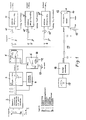
- a period T of the welding voltage 1 is shown in the block diagram in FIG. 1 of the electronic welding current generator.
- a higher generator pulse voltage Up is generated during the pulse phases tp and a lower generator basic voltage U G is generated during the basic phases t G , the basic phases t G preferably taking longer than the pulse phases tp.
- the welding voltage signal is given to an adaptation network 2, if necessary for adaptation of the measured value and / or for standardization and possibly for electrical isolation.
- the output signal of the network 2 is fed to a sample-and-hold circuit 3 for time-selective detection of the straight branch of the basic voltage U G of the welding voltage signal; at the same time, the output signal from the network 2 is applied in parallel to a module 4 for the selection and determination of the basic phase t G.
- This module 4 is used to delay the sample signal when the measuring voltage drops, but to switch it off immediately when the measuring voltage increases, so that actually only the horizontal branch of the basic voltage U G is detected.
- This measured value E obtained in this way is directly proportional to the real length LL of the arc.
- the measured value E is updated by each period T of the welding voltage, so that an updated measured value E proportional to the arc length LL is always available at the output of the sample-and-hold circuit 3; this measured value E thus represents the actual value of the basic voltage U G , which is directly proportional to the arc length LL that actually acts.
- the target value SWU LL is obtained from a block 6 of the comparison of this measured value E (actual value U G) is carried out with an adjustable set value for the arc length SWLL, which is preferably a voltage value SWU LL.
- the basic voltage U o is set via a potentiometer 19 of the module 6. In this way, the control deviation ⁇ X is obtained at the input of the PI controller 5, which is fed to the PI controller 5.
- a characteristic curve taking into account all process influences can be set, similar to the rigid VDE characteristic curve.
- the control deviation ⁇ X w is amplified by the PI controller 5 to the manipulated variable ⁇ Y, which represents the control output variable.
- the process parameters required in pulse technology such as setpoints, pulse voltage Up, pulse phase tp or basic phase t G, can now be incrementally or decrementally intervened.
- the degree of intervention, that is the control factor a can be designed to be adjustable or rigid.
- the manipulated variable ⁇ Y is given in parallel through a diode 7 in the forward direction to a switch 9 for the control mode "pulse voltage increase with tendency to arc shortening", i.e. If the arc length decreases, the pulse voltage is increased until the original arc length is reached again with this type of control.
- This type of control optimizes the welding process in particular.
- the manipulated variable ⁇ Y is applied via a diode 7 ', which is polarized in the forward direction, to a switch 9' for the control type "pulse voltage increase and pulse time increase with a tendency to shorten the arc", i.e. If the arc length decreases, the pulse voltage and the pulse width are increased until the original arc length is reached again.
- the manipulated variable ⁇ Y is applied to a switch 9 "via a diode 8 switched in the reverse direction in order to generate the control type" pulse voltage increase with a tendency to shorten the arc and increase in the base time with a tendency to extend the arc ", ie the control type serves to increase the pulse voltage when the arc length decreases and to increase the base time when the arc length increases Arc voltage and is mainly used for manual welding.
- a potentiometer 10, 10', 10" is arranged in front of each module 11, 11 ', 11 "in order to control factor a or a1 or
- SWU t p U t p + dU t p for module 11 'or
- SWU tG U tG + dU tG for module 11 ".
- This setpoint can now be used as a control variable in a suitable power unit used will.
- the manipulated variable ⁇ Y is equally given, preferably via an RC network 15, for averaging, a limit indicator 12 and, in parallel, a module 16 for display adaptation, the output signal of which is given to a display instrument 17 which is capable of displaying a ⁇ zero deviation.
- the limit indicator 12 signals to the user when the increased service life has been reached due to the higher-level control of the control types mentioned.
- the arithmetic averaging of the manipulated variable suppresses rapid manipulated variable swings.
- the limit indicator 12 is blocked by means of a switch 14 in the adjustment position and during the ignition phase of a welding process in order to avoid incorrect messages; it is released with a delay.
- the limit value voltage U Gw can be specified to the limit value detector 12 via a potentiometer 13.
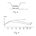
- FIG. 2 shows the acquisition of the basic voltage by the sample-and-hold circuit 3.
- the sample-and-hold signal is only applied to the measuring voltage during the basic phase t G when the basic voltage U G has actually been reached, ie that in this way only the horizontal branch of the measuring voltage is detected.
- the basic voltage is stored and is available in the hold phase as a preferably positive actual value signal for the subsequent setpoint / actual value comparison.
- the setpoint / actual value comparison takes place at the input of the PI controller 5, whose PI behavior can be predetermined in a changeable manner.
- Figure 3 shows the relationship between the control factor and the basic phase t G and the control voltage U tG . It can be seen that at short t G times the controller intervention is weakened because the so-called "internal control" is more effective, ie the tp phase is relatively large compared to the period duration T. At long t G times, From around 15 ms, the controller intervention becomes degressive so that the pulse frequency does not become too low.
Abstract
Die Erfindung betrifft einen elektronischen Schweißstrom-Generator für das Impuls-Lichtbogenschweißen, mit einem durch elektrische Führungsgrößen steuerbaren Leistungsteil, die über elektronische Schaltkreise vorgebbar sind, wobei im Pulsbetrieb (T) jeweils während der Pulsphasen (tp) ein höherer Generator-Pulsstrom (Ip) oder eine höhere Generator-Pulspannung (UP) und jeweils während der Grundphasen (tG) ein niedrigerer Generator-Grundstrom (IG) oder Generator-Grundspannung (UG) erzeugbar sind. Ausgehend von der Up-IG-Modulation werden während der Pulsphasen (tp) die Pulsspannung (UP) und während der der Grundphasen (tG) der Grundstrom (IG) geregelt; während der Grundphasen (tG) wird zeitselektiv die Grundspannung (UG) gemessen, der Meßwert (E) gespeichert und nach jeder Pulsperiode (T) aktualisiert, wobei der aktualisierte Meßwert (E) der Grundspannung (UG) in direkter Proportionalität zur real wirkenden Länge (LL) des Lichtbogens erhalten wird. Dieser aktualisierte Meßwert (E) dient zur übergeordneten Regelung des Schweißprozesses, indem der Meßwert (E), der die Länge (LL) des Lichtbogens wiedergibt, mit einem einstellbaren Sollwert (SWLL) für die Länge des Lichtbogens verglichen und mit einem nachgeschalteten PI-Regler verstärkt wird, mit dem Ziel der genannten übergeordneten Führungsregelung. <IMAGE>The invention relates to an electronic welding current generator for pulsed arc welding, with a power section that can be controlled by electrical reference variables and that can be specified via electronic circuits, with a higher generator pulse current (Ip) in pulse mode (T) during the pulse phases (tp). or a higher generator pulse voltage (UP) and a lower generator basic current (IG) or generator basic voltage (UG) can be generated in each case during the basic phases (tG). Starting from the up-IG modulation, the pulse voltage (UP) is regulated during the pulse phases (tp) and the basic current (IG) is regulated during that of the basic phases (tG); during the basic phases (tG), the basic voltage (UG) is measured in a time-selective manner, the measured value (E) is saved and updated after each pulse period (T), the updated measured value (E) of the basic voltage (UG) being directly proportional to the real length ( LL) of the arc is obtained. This updated measured value (E) is used to control the welding process by comparing the measured value (E), which represents the length (LL) of the arc, with an adjustable setpoint (SWLL) for the length of the arc and with a downstream PI controller is strengthened with the aim of the higher-level management regulation mentioned. <IMAGE>
Description
Die Erfindung betrifft einen elektronischen Schweißstrom-Generator gemäß dem Oberbegriff des Patentanspruchs 1.The invention relates to an electronic welding current generator according to the preamble of
Die reale Lichtbogenspannung kann zu Zwekken der Regelung der Pulsspannung als Istwert nicht direkt erfaßt werden, da am Lichtbogen kein elektrischer Abgriff möglich ist. In den meisten Fällen wird deshalb der Spannungs-Istwert an den Ausgangsklemmen der Schweiß-Stromquelle abgegriffen.The real arc voltage cannot be directly recorded as actual value for the purpose of regulating the pulse voltage, since electrical tapping is not possible on the arc. In most cases, the actual voltage value is therefore tapped at the output terminals of the welding power source.
Der Sollwert Up der Pulsspannung wird unter Beachtung auch der anderen relevanten Parameter so eingestellt, bis der Schweißprozeß optimal läuft. Dabei ist die wirksame Lichtbogenspannung kleiner als die geregelte Generatorausgangsspannung. Die Differenz ergibt sich aus dem Spannungsabfall an den Schweißkabeln und dem Spannungsabfall an der Kontaktdüse.The setpoint value Up of the pulse voltage is set taking into account the other relevant parameters until the welding process runs optimally. The effective arc voltage is less than the regulated generator output voltage. The difference results from the voltage drop at the welding cables and the voltage drop at the contact nozzle.
Diese Spannungsabfälle erhöhen sich im Verlauf der Zeit durch Widerstandserhöhung der sich erwärmenden Schweißkabel und der verschleißenden Kontaktdüse. Die am Lichtbogen verfügbare Spannung sinkt demgemäß, der Lichtbogen wird kürzer und die Spritzerhäufigkeit nimmt zu bis hin zur völligen Entgleisung des Prozesses.These voltage drops increase over time due to an increase in the resistance of the heating welding cables and the wearing contact nozzle. The voltage available on the arc decreases accordingly, the arc becomes shorter and the frequency of spatter increases up to the point where the process is completely derailed.
Durch Beobachtung der Lichtbogenlänge und entsprechender Erhöhung des Sollwertpotentiometers der Pulsspannung Up läßt sich die tendenziell verringernde Lichtbogenlänge manuell korrigieren und damit im gewünschten Sinn konstant hatten. Diese Methode überfordert jedoch das Bedienungspersonal und verbietet sich aus Kostengründen und mangelnder Qualitätssicherung von selbst.By observing the arc length and correspondingly increasing the setpoint potentiometer of the pulse voltage Up, the tendency to reduce the arc length can be corrected manually and thus had the desired constant. However, this method overwhelms the operating personnel and is prohibited by itself due to cost reasons and a lack of quality assurance.
Deshalb wird in der Praxis nach Erfahrung gehandelt. Nach einer ermittelten Zahl von Schweißzyklen wird die Kontaktdüse prinzipiell vorsorglich gewechselt. Diese Methode ist zwar praktikabel sie führt jedoch zu einem hohen Düsenverbrauch und zu relativ hohen Stillstandzeiten und damit zu vermeidbaren hohen Kosten.For this reason, experience is used in practice. After a determined number of welding cycles, the contact nozzle is in principle changed as a precaution. Although this method is practicable, it leads to high nozzle consumption and relatively long downtimes and thus to avoidable high costs.
Da dieser sich zeitlich erhöhende, schädliche Spannungsabfall an der Kontaktdüse und den sich erwärmenden Schweißkabeln nur in der Pulsspannungsphase signifikant ist, also während der Pulsphase tp entsteht, wäre es naheliegend, statt der Up-IG-Modulation das Prinzip der Ip-IG-Modulation anzuwenden, da konstante Ströme am Prozeßwiderstand konstante Spannungsabfälle erzeugen.Da hierbei jedoch die sogenannte "innere Regelung" der Up-IG-Modulation nicht vorhanden ist, muß die Prozeßstabilität mit Hilfe der Pulszeitregelung (tp-Regelung) erzwungen werden. Diese Methode erhöht zweifellos die Düsenstandzeit, führt jedoch nachweislich zu schlechteren Schweißqualitäten.Since this time-increasing, harmful voltage drop at the contact nozzle and the warming welding cables is only significant in the pulse voltage phase, i.e. occurs during the pulse phase tp, it would be obvious to use the principle of Ip-I G instead of Up-I G modulation. Apply modulation, since constant currents at the process resistor produce constant voltage drops. However, since the so-called "internal control" of the Up-I G modulation is not available, the process stability must be enforced using the pulse time control (tp control). This method undoubtedly increases the nozzle service life, but has been shown to lead to poorer welding qualities.
Der Erfindung liegt die Aufgabe zugrunde, bei einem elektronischen Schweißstrom-Generator der eingangs genannten Gattung Tendenzen zur Lichtbogenverkürzung oder -verlängerung von vorneherein sofort zu erkennen und wirksam zu unterdrükken bzw. auf eine eingestellte Länge zu regeln.The invention has for its object to immediately recognize and effectively suppress or regulate to a set length in an electronic welding current generator of the type mentioned tendencies to shorten or extend the arc.
Die Aufgabe wird durch einen elektronischen Schweißstrom-Generator gemäß den folgenden Merkmalen des Anspruchs 1 gelöst:
- a) ausgehend von der Up-IG-Modulation werden während der Pulsphasen (tp) die Pulsspannung (Up) und während der Grundphasen (tG) der Grundstrom (IG) geregelt
- b) während der Grundphasen (tG) wird zeitselektiv die Grundspannung (UG) gemessen, der Meßwert (E) gespeichert und nach jeder Pulsperiode (T) aktualisiert
- c) der aktualisierte Meßwert (E) der Grundspannung (UG) wird in direkter Proportionalität zur real wirkenden Länge (LL) des Lichtbogens erhalten
- d) der aktualisierte Meßwert (E) dient zur übergeordneten Regelung des Schweißprozesses, indem der Meßwert (E), der die Länge (LL) des Lichtbogens wiedergibt, mit einem einstellbaren Sollwert (SWLL) für die Länge des Lichtbogens verglichen wird. Die sich aus dem aktualisierten Meßwert (E) und dem Sollwert (SWLL, SWUu) ergebende Regelabweichung (±XW) wird einem nachgeschalteten PI-Regler aufgegeben und zur Stellgröße (±Y) verstärkt, die auf die Prozeßparameter, wie Sollwerte (Up, tp, tG) inkrementierend oder dekrementierend einzuwirken imstande ist, wobei die Eingriffsstärke (Regelfaktor) einstellbar gestaltet oder starr festlegbar ist. Weitere vorteilhafte Ausgestaltungen der Erfindung sind in den Unteransprüchen gekennzeichnet.
- a) starting from the Up-I G modulation, the pulse voltage (Up) is regulated during the pulse phases (tp) and the basic current (I G ) is regulated during the basic phases (t G )
- b) during the basic phases (t G ) the basic voltage (U G ) is measured in a time-selective manner, the measured value (E) is stored and updated after each pulse period (T)
- c) the updated measured value (E) of the basic voltage (U G ) is obtained in direct proportionality to the real effective length (LL) of the arc
- d) the updated measured value (E) serves to control the welding process by comparing the measured value (E), which represents the length (LL) of the arc, with an adjustable target value (SWLL) for the length of the arc. The control deviation (± X W ) resulting from the updated measured value (E) and the setpoint (SWLL, SWU u ) is given to a downstream PI controller and amplified to the manipulated variable (± Y), which is related to the process parameters such as setpoints (Up , tp, t G ) is able to act incrementally or decrementally, the degree of intervention (control factor) being adjustable or rigidly determinable. Further advantageous embodiments of the invention are characterized in the subclaims.
Die Erfindung besitzt den hervorstechenden Vorteil, daß durch die Lichtbogenlängenregelung beim Pulslichtbogenschweißen in beiden Richtungen die Prozeßstabilität erhöht, der Kontaktdüsenverbrauch erheblich verringert und die Stillstandszeiten herabgesetzt werden. In einer praktischen Versuchsanordnung konnte die Kontaktdüsenstandzeit beim Einsatz der Erfindung auf das 5fache von Schweißzyklen erhöht werden. Ebenso bleibt beim Handschweißen, wie Pendeln in einer Kehlnaht, die Lichtbogenlänge stabil; zusätzlich wird die Spritzerhäufigkeit stark reduziert. Des weiteren ist der Einfluß der Schweißkabelwiderstandserhöhung bei der Erwärmung der Schweißkabel nunmehr ohne Einfluß auf den Schweißprozeß.The invention has the salient advantage that the arc length control in pulsed arc welding increases the process stability in both directions, the contact nozzle consumption is considerably reduced and the downtimes are reduced. In a practical test arrangement, the contact nozzle service life could be increased to 5 times the welding cycles when using the invention. The arc length also remains stable during manual welding, such as swinging in a fillet weld; in addition, the frequency of spatter is greatly reduced. Furthermore, the influence of the increase in welding cable resistance is Heating of the welding cables now has no influence on the welding process.
Der Kern der Erfindung liegt in der Erfassung eines Meßwertes, der sich direkt proportional zur real wirkenden Lichtbogenlänge verhält, wobei vorteilhaft das Prinzip der Pulstechnik mit Up-IG-Modulation verwendet wird. Während der Pulsphase tp wird die Pulsspannung Up geregelt, während der Grundphase tG hingegen der Grundstrom IG. Wird während der Grundphase tG zeitselektiv die Generatorspannung gemessen, gespeichert und nach jeder Pulsperiode aktualisiert, dann wird auf diese Weise ein der Lichtbogenlänge proportionaler Meßwert erhalten, der in hervorragender Weise für eine die Lichtbogenlänge erhaltende, übergeordnete Regelung zur Verfügung steht.The essence of the invention lies in the acquisition of a measured value which is directly proportional to the actual arc length, the principle of pulse technology with Up-I G modulation being advantageously used. The pulse voltage Up is regulated during the pulse phase tp, while the basic current I G is regulated during the basic phase t G. If the generator voltage is measured time-selectively during the basic phase t G , stored and updated after each pulse period, a measurement value proportional to the arc length is obtained in this way, which is excellently available for a higher-level control system that maintains the arc length.
Dieser Istwert "Lichtbogenlänge" wird mit einem einstellbaren Sollwert "Lichtbogenlänge" verglichen und die sich daraus ergebende Regelabweichung ±XW durch einen nachgeschalteten Pl-Regler zur Stellgröße ±Y verstärkt. Der Sollwert folgt dabei der Beziehung ULL = Uo + m • UG; darin bedeuten:
- ULL = Sollwert Lichtbogenlänge
- Uo = Grundspannung (einstellbar z.B. über Potentiometer zwischen 13-20V)
- m = Neigungsfaktor mit Einsteller, einstellbar (z.B. auf Platine) von 0,02-0,05
- U LL = setpoint arc length
- Uo = basic voltage (adjustable e.g. via potentiometer between 13-20V)
- m = inclination factor with adjuster, adjustable (e.g. on circuit board) from 0.02-0.05
UIG = Leitspannung für den Grundstrom IG Damit läßt sich in vorteilhafter Weise eine alle Prozeßeinflüsse berücksichtigende Kennlinie einstellen, die ähnlich der starren VDE-Kennlinie erhalten werden kann.U IG = master voltage for the base current I G This advantageously allows a characteristic curve that takes into account all process influences, which can be obtained similar to the rigid VDE characteristic curve.
Mit der Reglerausgangsgröße ±Y kann in vielfältiger Weise auf die in der Pulstechnik benötigten Prozeßparameter, wie Sollwerte Up, tp oder tG, inkrementierend oder dekrementierend eingegriffen werden, wobei die Eingriffsstärke, der Regelfaktor, einstellbar gestaltet oder starr festgelegt sein kann.With the controller output variable ± Y, the process parameters required in pulse technology, such as setpoints Up, tp or t G , can be incrementally or decrementally intervened, the degree of intervention, the control factor, being adjustable or rigidly defined.
Zur Verdeutlichung des erfindungsgemäßen Prinzips sollen die nachfolgenden Regelarten dienen:
- Regelart "Pulsspannungserhöhung bei Tendenz zur Lichtbogenverkürzung":
- Wirksamer Sollwert Up = eingestellter Sollwert Up + ΔUp, wobei bedeuten:
- Up = α•(+Y); der Wert -Y wird unterdrückt a = Eingriffsstärke (Regelfaktor)
- Regelart "Pulsspannungserhöhung und Pulszeiterhöhung bei Tendenz zur Lichtbogenverkürzung":
- Wirksamer Sollwert Up = eingestellter Sollwert Up + ΔUp
- Rule type "pulse voltage increase with tendency to arc shortening":
- Effective setpoint Up = setpoint Up + ΔUp, where:
- Up = α • (+ Y); the value -Y is suppressed a = degree of intervention (control factor)
- Rule type "increase in pulse voltage and increase in pulse time with tendency to shorten the arc":
- Effective setpoint Up = setpoint Up + ΔU p
Wirksamer Sollwert Utp = eingestellter Sollwert Utp + DUtp; wobei bedeuten:
- ΔUp = α•(+Y); der Wert-Y wird unterdrückt

- Die beiden genannten Regelarten eignen sich vorzugsweise zum automatischen Schweißen und hierbei insbesondere zum Erhöhen der Kontaktdüsenstandzeit und der Beseitigung der Einflüsse der Zuleitungskabel.
- Regelart "Pulsspannungserhöhung bei Tendenz zur Lichtbogenverkürzung sowie Grundzeiterhöhung bei Tendenz zur Lichtbogenverlängerung":
- Wirksamer Sollwert Up = eingestellter Sollwert Up + ΔUp
- Wirksamer Sollwert UtG = eingestellter Sollwert UtG + AUto; wobei bedeuten:
- ΔUp = α•(+Y); der Wert - Y wird unterdrückt
- AUto = a2'(-Y); der Wert + Y wird unterdrückt.
- ΔUp = α • (+ Y); the value-Y is suppressed
- The two types of control mentioned are preferably suitable for automatic welding and in particular for increasing the contact nozzle service life and eliminating the influences of the supply cables.
- Rule type "increase in pulse voltage when there is a tendency to shorten the arc and increase in base time when there is a tendency to extend the arc":
- Effective setpoint Up = setpoint Up + ΔU p
- Effective setpoint U tG = set setpoint U tG + AUto; where mean:
- ΔUp = α • (+ Y); the value - Y is suppressed
- AUto = a2 '(- Y); the value + Y is suppressed.
Diese Up-tG-Regelart eignet sich vorzugsweise zum manuellen Schweißen.This Up-t G control type is particularly suitable for manual welding.
Je nach Anwendung kann eine der drei vorgenannten Regelarten vorgegeben bzw. eingeschaltet werden. Voraussetzung hierfür ist ein optimal eingestellter Schweißprozeß, wobei ein vorhandener Regelartschalter in der Stellung Abgleich" stehen muß. Der Sollwert der Spannung "Lichtbogenlänge" SWULLwird bei laufendem Prozeß so eingestellt, bis die Stellgröße ±Y = 0 ist. Dazu kann die Stellgröße auf eine Differenzanzeige beliebiger Bauart geschaltet sein, z.B. auf ein Nullpunkt-Instrument oder LED-Zeilen-Anzeige o.ä., um positive und negative Abweichungen von Null zu erkennen. In dieser Abgleichstellung wirkt der PI-Regler nur als P-Regler mit definierter Verstärkung und somit in Funktion als Anzeigeverstärker. Nach erfolgtem Abgleich kann dann auf die gewünschte Regelart geschaltet werden; danach sollten die Prozeßparameter nicht mehr verstellt werden. Ist dies zum Beispiel bei einer anderen Schweißaufgabe erforderlich, ist zuerst ein einmaliger Neuabgleich notwendig. Dieser Abgleich kann auch selbsttätig gestaltet werden (autom. Nullpunktabgleich).Depending on the application, one of the three aforementioned control types can be specified or switched on. The prerequisite for this is an optimally set welding process, whereby an existing control switch must be in the adjustment position. The setpoint value of the "arc length" voltage SWU LL is set during the running process until the manipulated variable is ± Y = 0 a differential display of any type can be switched, for example on a zero point instrument or LED line display, etc., in order to detect positive and negative deviations from zero In this adjustment position, the PI controller only acts as a P controller with a defined gain and thus functions as a display amplifier. Once the adjustment has been made, you can then switch to the desired control type, after which the process parameters should no longer be adjusted. If this is necessary for another welding task, for example, a one-time readjustment is necessary. This adjustment can also be carried out automatically be designed (automatic zero point adjustment).
Der Regel-Stellgröße ±Y kann ein Grenzwertmelder zugeordnet sein, der dem Anwender signalisiert, wann die erhöhte Standzeit erreicht ist. Als Eingangsgröße erhält der Grenzwertmelder vorzugsweise den arithmetischen Mittelwert der Stellgröße, wodurch schnelle Stellgrößenausschläge unterdrückt werden.The control manipulated variable ± Y can be assigned a limit indicator that signals to the user when the increased service life has been reached. The limit value detector preferably receives the arithmetic mean value of the manipulated variable as an input variable, thereby suppressing rapid manipulated variable fluctuations.
Vorzugsweise ist der Grenzwertmelder in der Abgleichstellung und während der Zündphase eines Schweißprozesses gesperrt, um Fehlmeldungen zu vermeiden; er wird somit verzögert freigegeben. Der Grenzwert kann mit einem zugeordneten Potentiometer zur Einstellung der Grenzwertspannung UGw eingestellt werden.The limit value detector is preferably blocked in the adjustment position and during the ignition phase of a welding process in order to avoid false messages; it is thus released with a delay. The limit value can be set with an assigned potentiometer for setting the limit value voltage U Gw .
Kurzbeschreibung der Zeichnung, in der zeigen:
Figur 1 ein Blockschaltbild des elektronischen Schweißstrom-GeneratorsFigur 2 die Erfassung der Grundspannung durch Sample-and-Hold undFigur 3 die Darstellung des Zusammenhangs zwischen dem Regelfaktor, dem wirksamen Spannungs-Sollwert Up der Pulsphase tG bei der Up-tG-Regelung.
- Figure 1 is a block diagram of the electronic welding current generator
- Figure 2 the detection of the basic voltage by sample and hold and
- Figure 3 shows the relationship between the control factor, the effective voltage setpoint Up of the pulse phase t G in the Up-t G control .
Eine Periode T der Schweißspannung 1 ist im Blockschaltbild Figur 1 des elektronischen Schweißstrom-Generators dargestellt. Im Pulsbetrieb wird während der Pulsphasen tp eine höhere Generator-Pulsspannung Up und während der Grundphasen tG eine niedrigere Generator-Grundspannung UG erzeugt, wobei vorzugsweise die Grundphasen tG zeitlich länger dauern als die Pulsphasen tp. Das Schweißspannungssignal wird einem Anpassungsnetzwerk 2 aufgegeben gegebenenfalls zur Anpassung des Meßwertes und/oder zur Normierung und eventuell zur galvanischen Trennung. Das Ausgangssignal des Netzwerkes 2 wird zur zeitselektiven Erfassung des geraden Astes der Grundspannung UG des Schweißspannungssignals einer Sample-and-Hold-Schaltung 3 zugeführt; gleichzeitig wird das Ausgangssignal aus dem Netzwerk 2 parallel auf einen Baustein 4 für die Selektion und Festlegung der Grundphase tG aufgegeben. Dieser Baustein 4 dient dazu, bei sinkender Meßspannung das Sample-Signal zu verzögern, bei steigender Meßspannung hingegen sofort auszuschalten, damit tatsächlich nur der waagrechte Ast der Grundspannung UG erfaßt wird. Dieser so erhaltene Meßwert E ist direkt proportional zur real wirkenden Länge LL des Lichtbogens. Der Meßwert E wird durch jede Periode T der Schweißspannung aktualisiert, so daß immer ein aktualisierter Meßwert E proportional der Lichtbogenlänge LL am Ausgang der Sample-and-Hold-Schaltung 3 zur Verfügung steht; dieser Meßwert E gibt somit den Istwert der Grundspannung UG wieder, der direkt proportional zur real wirkenden Lichtbogenlänge LL ist.A period T of the
Nun erfolgt der Vergleich dieses Meßwertes E (Istwert UG) mit einem einstellbaren Sollwert für die Lichtbogenlänge SWLL, der vorzugsweise ein Spannungswert SWULL ist, wobei der Sollwert SWULL aus einem Baustein 6 gewonnen wird. Der Sollwert der Spannung SWULL folgt der Beziehung: SWULL = Uo + m UG, wobei der Neigungsfaktor m mittels eines Potentiometers 18 einstellbar ist, der mit der zugeführten Leitspannung UIG des Grundstromes multipliziert wird. Über ein Potentiometer 19 des Bausteines 6 wird die Grundspannung U o eingestellt. Auf diese Weise wird am Eingang des PI-Reglers 5 die Regelabweichung ±X gewonnen, die dem PI-Regler 5 zugeführt wird.Now, wherein the target value SWU LL is obtained from a
Mit dieser Gleichung läßt sich eine alle Prozeßeinflüsse berücksichtigende Kennlinie einstellen, ähnlich der starren VDE-Kennlinie. Die Regelabweichung ± Xw wird durch den PI-Regler 5 zur Stellgröße ± Y verstärkt, die die Regelausgangsgröße darstellt. Mit der Regelausgangsgröße ± Y kann nun in vielfältiger Art auf die in der Pulstechnik benötigten Prozeßparameter, wie Sollwerte, Pulsspannung Up, Pulsphase tp oder Grundphase tG inkrementierend oder dekrementierend eingegriffen werden. Die Eingriffsstärke, das ist der Regelfaktor a, kann dabei einstellbar gestaltet oder starr festgelegt werden.With this equation, a characteristic curve taking into account all process influences can be set, similar to the rigid VDE characteristic curve. The control deviation ± X w is amplified by the
Im Blockschaltbild der Figur 1 wird dazu die Stellgröße ± Y parallel über eine Diode 7 in Durchlaßrichtung auf einen Schalter 9 für die Regelart "Pulsspannungserhöhung bei Tendenz zur Lichtbogenverkürzung" aufgegeben, d.h. bei sinkender Lichtbogenlänge wird bei dieser Regelart die Pulsspannung soweit erhöht, bis die ursprüngliche Lichtbogenlänge wieder erreicht ist. Diese Regelart optimiert insbesondere den Schweißprozeß.In the block diagram of Figure 1, the manipulated variable ± Y is given in parallel through a
Gleichzeitig wird die Stellgröße ± Y über eine in Durchlaßrichtung gepolte Diode 7' auf einen Schalter 9' für die Regelart "Pulsspannungserhöhung und Pulszeiterhöhung bei Tendenz zur Lichtbogenverkürzung" aufgegeben, d.h. bei sinkender Lichtbogenlänge werden die Pulsspannung und gleichzeitig die Pulsbreite soweit erhöht, bis die ursprüngliche Lichtbogenlänge wieder erreicht ist.At the same time, the manipulated variable ± Y is applied via a diode 7 ', which is polarized in the forward direction, to a switch 9' for the control type "pulse voltage increase and pulse time increase with a tendency to shorten the arc", i.e. If the arc length decreases, the pulse voltage and the pulse width are increased until the original arc length is reached again.
Gleichzeitig wird die Stellgröße ± Y über eine in Sperrichtung geschaltete Diode 8 einem Schalter 9" aufgegeben zu Erzeugung der Regelart "Pulsspannungserhöhung bei Tendenz zur Lichtbogenverkürzung sowie Grundzeiterhöhung bei Tendenz zur Lichtbogenverlängerung", d.h. die Regelart dient zur Pulsspannungserhöhung bei sinkender Lichtbogenlänge und zur Grundzeiterhöhung bei steigender Lichtbogenspannung und wird vorwiegend beim Handschweißen eingesetzt.At the same time, the manipulated variable ± Y is applied to a
Die Schalter 9, 9', 9" dienen zur Einstellung bzw. Wahl der Regelart. Vor jedem Baustein 11,11', 11" ist je ein Potentiometer 10, 10', 10" angeordnet, um den Regelfaktor a bzw. a1 bzw. a2 einzustellen. Die Bausteine 11, 11' und 11" bestehen aus aktiven Addier-Netzwerken, in denen durch Addition der entsprechenden Leitspannung plus dem Differential dieser Leitspannung der entsprechende Sollwert SW erzeugt wird, der vorzugsweise eine Spannung ist, nämlich einer der Sollwerte: SWUp = Up + dUp für den Baustein 11 SWUtp = Utp + dUtp für den Baustein 11' oder SWUtG = UtG + dUtG für den Baustein 11". Dieser jeweilige Sollwert kann nun in einem geeigneten Leistungsteil als Ansteuergröße verwendet werden.The
Die Stellgröße ± Y wird gleichermaßen, vorzugsweise über ein RC-Netzwerk 15, zur Mittelwertbildung einem Grenzwertmelder 12 und parallel hierzu einem Baustein 16 zur Anzeige-Anpassung aufgegeben, dessen Ausgangssignal auf ein Anzeigeinstrument 17 gegeben wird, das eine ± Nullabweichung anzuzeigen imstande ist. Der Grenzwertmelder 12 signalisiert dem Anwender, wann die durch die übergeordnete Regelung der genannten Regelarten erhöhte Standzeit erreicht ist. Durch die arithmetische Mittelwertbildung der Stellgröße werden schnelle Stellgrößenausschläge unterdrückt. Der Grenzwertmelder 12 ist mittels eines Schalters 14 in der Abgleichstellung und während der Zündphase eines Schweißprozesses gesperrt, um Fehlmeldungen zu vermeiden; er wird verzögert freigegeben. Die Grenzwertspannung UGw kann über ein Potentiometer 13 dem Grenzwertmelder 12 vorgegeben werden.The manipulated variable ± Y is equally given, preferably via an
In Figur 2 ist die Erfassung der Grundspannung durch den Sample-and-Hold-Schaltkreis 3 dargestellt. Das Sample-and-Hold-Signal wird nur während der Grundphase tG an die Meßspannung gelegt, wenn tatsächlich die Grundspannung UG erreicht ist, d.h. daß auf diese Weise nur der waagrechte Ast der Meßspannung erfaßt wird. Die Grundspannung wird gespeichert und steht in der Hold-Phase als vorzugsweise positives Istwertsignal für den nachfolgenden Soll-Istwertvergleich zur Verfügung.FIG. 2 shows the acquisition of the basic voltage by the sample-and-
Der Soll-Istwertvergleich erfolgt am Eingang des PI-Reglers 5, dessen Pl- Verhalten in veränderbarer Weise vorgegeben werden kann.The setpoint / actual value comparison takes place at the input of the
Figur 3 zeigt den Zusammenhang zwischen dem Regelfaktor und der Grundphase tG sowie von der Leitspannung UtG. Dabei erkennt man, daß bei kleinen tG-Zeiten der Reglereingriff abgeschwächt wird, weil hierbei die sogenannte "Innere Regelung" stärker wirksam ist, d.h., die tp-Phase ist relativ groß im Vergleich zur Periodendauer T. Bei großen tG-Zeiten, ungefähr ab 15 ms, wird der Reglereingriff degressiv, damit die Pulsfrequenz nicht zu niedrig wird.Figure 3 shows the relationship between the control factor and the basic phase t G and the control voltage U tG . It can be seen that at short t G times the controller intervention is weakened because the so-called "internal control" is more effective, ie the tp phase is relatively large compared to the period duration T. At long t G times, From around 15 ms, the controller intervention becomes degressive so that the pulse frequency does not become too low.
Liste der Bezugszeichen:


Claims (10)
Applications Claiming Priority (2)
| Application Number | Priority Date | Filing Date | Title |
|---|---|---|---|
| DE4121237A DE4121237C2 (en) | 1991-06-27 | 1991-06-27 | Electronic welding current generator for pulsed arc welding |
| DE4121237 | 1991-06-27 |
Publications (2)
| Publication Number | Publication Date |
|---|---|
| EP0520439A2 true EP0520439A2 (en) | 1992-12-30 |
| EP0520439A3 EP0520439A3 (en) | 1994-11-09 |
Family
ID=6434867
Family Applications (1)
| Application Number | Title | Priority Date | Filing Date |
|---|---|---|---|
| EP9292110696A Withdrawn EP0520439A3 (en) | 1991-06-27 | 1992-06-25 | Electronic welding current generator for pulsed-arc welding |
Country Status (5)
| Country | Link |
|---|---|
| US (1) | US5293027A (en) |
| EP (1) | EP0520439A3 (en) |
| JP (1) | JPH06155025A (en) |
| CA (1) | CA2072711A1 (en) |
| DE (1) | DE4121237C2 (en) |
Cited By (1)
| Publication number | Priority date | Publication date | Assignee | Title |
|---|---|---|---|---|
| US6307177B1 (en) | 1997-04-25 | 2001-10-23 | Kuka Schweissanlagen Gmbh | Method and device for determining the voltage at welding power sources |
Families Citing this family (30)
| Publication number | Priority date | Publication date | Assignee | Title |
|---|---|---|---|---|
| US5756966A (en) * | 1995-09-22 | 1998-05-26 | General Electric Company | Method for joining metal components with improved arc voltage sensing and control |
| TW445192B (en) | 1999-04-12 | 2001-07-11 | Tri Tool Inc | Control method and apparatus for an arc welding system |
| DE10033387C2 (en) * | 2000-07-08 | 2002-11-07 | Nimak Lichtbogenschweismaschin | Method and device for welding or soldering metal using a pulsed arc |
| US10040143B2 (en) | 2012-12-12 | 2018-08-07 | Illinois Tool Works Inc. | Dabbing pulsed welding system and method |
| US10906114B2 (en) | 2012-12-21 | 2021-02-02 | Illinois Tool Works Inc. | System for arc welding with enhanced metal deposition |
| US9950383B2 (en) | 2013-02-05 | 2018-04-24 | Illinois Tool Works Inc. | Welding wire preheating system and method |
| US10835983B2 (en) | 2013-03-14 | 2020-11-17 | Illinois Tool Works Inc. | Electrode negative pulse welding system and method |
| US11045891B2 (en) | 2013-06-13 | 2021-06-29 | Illinois Tool Works Inc. | Systems and methods for anomalous cathode event control |
| US10828728B2 (en) | 2013-09-26 | 2020-11-10 | Illinois Tool Works Inc. | Hotwire deposition material processing system and method |
| US9539662B2 (en) | 2013-10-30 | 2017-01-10 | Illinois Tool Works Inc. | Extraction of arc length from voltage and current feedback |
| US11154946B2 (en) | 2014-06-30 | 2021-10-26 | Illinois Tool Works Inc. | Systems and methods for the control of welding parameters |
| US11198189B2 (en) | 2014-09-17 | 2021-12-14 | Illinois Tool Works Inc. | Electrode negative pulse welding system and method |
| US11478870B2 (en) | 2014-11-26 | 2022-10-25 | Illinois Tool Works Inc. | Dabbing pulsed welding system and method |
| US10189106B2 (en) | 2014-12-11 | 2019-01-29 | Illinois Tool Works Inc. | Reduced energy welding system and method |
| US11370050B2 (en) | 2015-03-31 | 2022-06-28 | Illinois Tool Works Inc. | Controlled short circuit welding system and method |
| US11285559B2 (en) | 2015-11-30 | 2022-03-29 | Illinois Tool Works Inc. | Welding system and method for shielded welding wires |
| US10610946B2 (en) | 2015-12-07 | 2020-04-07 | Illinois Tool Works, Inc. | Systems and methods for automated root pass welding |
| US10675699B2 (en) | 2015-12-10 | 2020-06-09 | Illinois Tool Works Inc. | Systems, methods, and apparatus to preheat welding wire |
| US10766092B2 (en) | 2017-04-18 | 2020-09-08 | Illinois Tool Works Inc. | Systems, methods, and apparatus to provide preheat voltage feedback loss protection |
| US10870164B2 (en) | 2017-05-16 | 2020-12-22 | Illinois Tool Works Inc. | Systems, methods, and apparatus to preheat welding wire |
| CA3066687C (en) | 2017-06-09 | 2022-08-02 | Illinois Tool Works Inc. | Welding torch, with two contact tips and a plurality of liquid cooling assemblies for conducting currents to the contact tips |
| CN111386167A (en) | 2017-06-09 | 2020-07-07 | 伊利诺斯工具制品有限公司 | A contact tip having a thread and a head to effect loosening by the thread, or a thread comprising a longitudinal slot for gas flow; welding torch with contact tip |
| WO2018227194A1 (en) | 2017-06-09 | 2018-12-13 | Illinois Tool Works Inc. | Welding assembly for a welding torch, with two contact tips and a cooling body to cool and conduct current |
| US11524354B2 (en) | 2017-06-09 | 2022-12-13 | Illinois Tool Works Inc. | Systems, methods, and apparatus to control weld current in a preheating system |
| CA3066619C (en) | 2017-06-09 | 2022-07-19 | Illinois Tool Works Inc. | Welding torch with a first contact tip to preheat welding wire and a second contact tip |
| US11020813B2 (en) | 2017-09-13 | 2021-06-01 | Illinois Tool Works Inc. | Systems, methods, and apparatus to reduce cast in a welding wire |
| WO2020047438A1 (en) | 2018-08-31 | 2020-03-05 | Illinois Tool Works Inc. | Submerged arc welding systems and submerged arc welding torches to resistively preheat electrode wire |
| US11014185B2 (en) | 2018-09-27 | 2021-05-25 | Illinois Tool Works Inc. | Systems, methods, and apparatus for control of wire preheating in welding-type systems |
| EP3898055A2 (en) | 2018-12-19 | 2021-10-27 | Illinois Tool Works, Inc. | Contact tip, wire preheating assembly, contact tip assembly and consumable electrode-fed welding type system |
| US11772182B2 (en) | 2019-12-20 | 2023-10-03 | Illinois Tool Works Inc. | Systems and methods for gas control during welding wire pretreatments |
Citations (8)
| Publication number | Priority date | Publication date | Assignee | Title |
|---|---|---|---|---|
| CH629134A5 (en) * | 1977-09-19 | 1982-04-15 | Oerlikon Buehrle Schweisstech | DEVICE FOR MIG-PULSE ARC WELDING. |
| US4409465A (en) * | 1981-04-24 | 1983-10-11 | Osaka Transformer Co., Ltd. | Pulse arc welding method and device in which pulse current and background current have a constant current characteristic |
| US4427874A (en) * | 1980-07-08 | 1984-01-24 | Mitsubishi Denki Kabushiki Kaisha | Pulse arc welding machine |
| EP0170248A2 (en) * | 1984-07-31 | 1986-02-05 | Matsushita Electric Industrial Co., Ltd. | Consumable electrode type pulse arc welding machine |
| US4620082A (en) * | 1982-08-31 | 1986-10-28 | Welding Institute Of Canada | Pulsed arc welding apparatus |
| US4758707A (en) * | 1986-06-04 | 1988-07-19 | Welding Industries Of Australia Pty., Ltd. | Pulsed arc welding |
| US4794232A (en) * | 1986-09-17 | 1988-12-27 | Kinetic Energy Corporation | Control for gas metal arc welding system |
| EP0387223A1 (en) * | 1989-03-06 | 1990-09-12 | ESAB Aktiebolag | Method for pulsed arc welding |
Family Cites Families (1)
| Publication number | Priority date | Publication date | Assignee | Title |
|---|---|---|---|---|
| US4529864A (en) * | 1983-05-23 | 1985-07-16 | Bennett Dale E | Closed loop control apparatus for short-circuit arc welding |
-
1991
- 1991-06-27 DE DE4121237A patent/DE4121237C2/en not_active Expired - Fee Related
-
1992
- 1992-06-25 EP EP9292110696A patent/EP0520439A3/en not_active Withdrawn
- 1992-06-29 CA CA002072711A patent/CA2072711A1/en not_active Abandoned
- 1992-06-29 US US07/905,825 patent/US5293027A/en not_active Expired - Fee Related
- 1992-06-29 JP JP4171278A patent/JPH06155025A/en active Pending
Patent Citations (8)
| Publication number | Priority date | Publication date | Assignee | Title |
|---|---|---|---|---|
| CH629134A5 (en) * | 1977-09-19 | 1982-04-15 | Oerlikon Buehrle Schweisstech | DEVICE FOR MIG-PULSE ARC WELDING. |
| US4427874A (en) * | 1980-07-08 | 1984-01-24 | Mitsubishi Denki Kabushiki Kaisha | Pulse arc welding machine |
| US4409465A (en) * | 1981-04-24 | 1983-10-11 | Osaka Transformer Co., Ltd. | Pulse arc welding method and device in which pulse current and background current have a constant current characteristic |
| US4620082A (en) * | 1982-08-31 | 1986-10-28 | Welding Institute Of Canada | Pulsed arc welding apparatus |
| EP0170248A2 (en) * | 1984-07-31 | 1986-02-05 | Matsushita Electric Industrial Co., Ltd. | Consumable electrode type pulse arc welding machine |
| US4758707A (en) * | 1986-06-04 | 1988-07-19 | Welding Industries Of Australia Pty., Ltd. | Pulsed arc welding |
| US4794232A (en) * | 1986-09-17 | 1988-12-27 | Kinetic Energy Corporation | Control for gas metal arc welding system |
| EP0387223A1 (en) * | 1989-03-06 | 1990-09-12 | ESAB Aktiebolag | Method for pulsed arc welding |
Cited By (1)
| Publication number | Priority date | Publication date | Assignee | Title |
|---|---|---|---|---|
| US6307177B1 (en) | 1997-04-25 | 2001-10-23 | Kuka Schweissanlagen Gmbh | Method and device for determining the voltage at welding power sources |
Also Published As
| Publication number | Publication date |
|---|---|
| CA2072711A1 (en) | 1992-12-28 |
| EP0520439A3 (en) | 1994-11-09 |
| DE4121237A1 (en) | 1993-01-07 |
| DE4121237C2 (en) | 1994-07-21 |
| JPH06155025A (en) | 1994-06-03 |
| US5293027A (en) | 1994-03-08 |
Similar Documents
| Publication | Publication Date | Title |
|---|---|---|
| EP0520439A2 (en) | Electronic welding current generator for pulsed-arc welding | |
| EP2495496A1 (en) | Burner assembly | |
| DE3407067A1 (en) | CONTROL CIRCUIT FOR GAS DISCHARGE LAMPS | |
| DE2422844C3 (en) | X-ray diagnostic apparatus in which the X-ray tube voltage is regulated via the X-ray tube heating current | |
| DE3407066A1 (en) | METHOD FOR SWITCHING ON LAMP GROUPS OF A GAS DISCHARGE LAMP LIGHTING SYSTEM AND LIGHTING SYSTEM FOR CARRYING OUT THE METHOD | |
| DE10352334A1 (en) | Microfocus X-ray equipment | |
| DE2728563A1 (en) | ROYAL DIAGNOSTIC GENERATOR WITH AN INVERTER FEEDING ITS HIGH VOLTAGE TRANSFORMER | |
| DE3325992A1 (en) | PROTECTIVE CIRCUIT AGAINST SHORT CIRCUIT FOR A LOW VOLTAGE SYNCHRONOUS GENERATOR WITH A VOLTAGE REGULATOR, ESPECIALLY FOR USE IN MOTOR VEHICLES | |
| DE2726890A1 (en) | FEEDING AND REGULATING CIRCUIT FOR A GAS-FILLED NEUTRON TUBE AND PROCEDURE FOR FEEDING AND REGULATING THE NEUTRON TUBE | |
| DE3932399C1 (en) | Operating series length regulating loop - switching in adjuster again during delay time if current falls again below threshold value | |
| EP0152543A1 (en) | Picture tube circuit | |
| DE1538609C3 (en) | Transistorized circuit arrangement for the automatic testing of printed cable runs | |
| EP3767174A1 (en) | Method and device for recalibrating a measuring system for regulating a fuel-air mixture in a heating device | |
| EP0427879A1 (en) | Device and methode for inductively heating workpieces | |
| EP1094592B1 (en) | Method for output voltage limitation for a voltage/frequency controlled converter with intermediate circuit and a converter | |
| DE3618025A1 (en) | Device for determining the control precision and the stability of control loops from measurement values and parameters of the control loop | |
| EP0590181A1 (en) | Method of determination of dwell of a primary circuit of an ignition system of a internal combustion engine | |
| DE3439115A1 (en) | PRINTER | |
| DE4318502C1 (en) | Method and circuit for monitoring the currents from power capacitors for power-factor correction | |
| DE4040008C2 (en) | Method and device for arc welding metallic objects | |
| DE4322597C2 (en) | Arrangement for high-resolution analog / digital conversion of signals with different signal amplitudes | |
| DE1563633C3 (en) | Power supply circuit | |
| DE960114C (en) | Method and device for regulating an alternating current or an alternating voltage | |
| DE744287C (en) | Procedure for balancing two-stage or multi-stage direct current amplifiers | |
| DE934182C (en) | X-ray apparatus |
Legal Events
| Date | Code | Title | Description |
|---|---|---|---|
| PUAI | Public reference made under article 153(3) epc to a published international application that has entered the european phase |
Free format text: ORIGINAL CODE: 0009012 |
|
| AK | Designated contracting states |
Kind code of ref document: A2 Designated state(s): AT BE CH DE DK ES FR GB GR IT LI LU MC NL PT SE |
|
| PUAL | Search report despatched |
Free format text: ORIGINAL CODE: 0009013 |
|
| AK | Designated contracting states |
Kind code of ref document: A3 Designated state(s): AT BE CH DE DK ES FR GB GR IT LI LU MC NL PT SE |
|
| STAA | Information on the status of an ep patent application or granted ep patent |
Free format text: STATUS: THE APPLICATION IS DEEMED TO BE WITHDRAWN |
|
| 18D | Application deemed to be withdrawn |
Effective date: 19950510 |