EP0520183A1 - Method and apparatus for debagging dust-containing or hazardous materials - Google Patents
Method and apparatus for debagging dust-containing or hazardous materials Download PDFInfo
- Publication number
- EP0520183A1 EP0520183A1 EP92108408A EP92108408A EP0520183A1 EP 0520183 A1 EP0520183 A1 EP 0520183A1 EP 92108408 A EP92108408 A EP 92108408A EP 92108408 A EP92108408 A EP 92108408A EP 0520183 A1 EP0520183 A1 EP 0520183A1
- Authority
- EP
- European Patent Office
- Prior art keywords
- bag
- chute
- basket
- holding tank
- bags
- Prior art date
- Legal status (The legal status is an assumption and is not a legal conclusion. Google has not performed a legal analysis and makes no representation as to the accuracy of the status listed.)
- Granted
Links
Images


Classifications
-
- B—PERFORMING OPERATIONS; TRANSPORTING
- B65—CONVEYING; PACKING; STORING; HANDLING THIN OR FILAMENTARY MATERIAL
- B65B—MACHINES, APPARATUS OR DEVICES FOR, OR METHODS OF, PACKAGING ARTICLES OR MATERIALS; UNPACKING
- B65B69/00—Unpacking of articles or materials, not otherwise provided for
- B65B69/0008—Opening and emptying bags
Definitions
- the present invention is directed to a method and apparatus for debagging dust-containing or hazardous materials, including method and apparatus for removing solid material from interior surfaces of a bag for complete removal of the contents of the bag and directing all of the bag contents into a holding tank. More particularly, the present invention is directed to a method and apparatus for removing dust-containing or hazardous material from a disposable bag by dropping the bag down a vertical bag-feeding chute that includes one or more fixed knife blades for slicing open the bag without knife blade movement; catching the sliced bag on a perforated receiving basket disposed above a solid or liquid level in a holding or mixing tank so that most of the contents drop downwardly into the holding tank; and washing or blowing entrained material from interior surfaces of the sliced bag and chute so that both the entrained material and any wash liquid used are directed into the mixing tank.
- wash liquid is used, the amount of wash liquid can be metered to obtain a precise and relatively accurate determination of the final concentration of the debagged material in the liquid combined therewith in the mixing tank.
- debagging apparatus used for debagging toxic and hazardous materials should not have a bag opening means that includes moving parts since some of the toxic or hazardous material may become clogged in an area of mechanical movement during operation, making operation and maintenance hazardous;
- many of the above-described debagging apparatus do not include a rinsing mechanism whereby dust-containing or hazardous materials remaining or entrained within the bag after substantially complete emptying can be carefully rinsed by hand, applying liquid essentially only to interior, usually plastic-lined surfaces of the bag to ensure that essentially all of the bagged material is rinsed from the bag and directed, together with rinse liquid, into a mixing tank without absorption of water-soluble material and rinse water onto an absorbent exterior bag surface; and the above-described apparatus do not include a metered wash liquid supply such that by rinsing an interior surface of the bag with rinse liquid, essentially all of the rinsed
- the method and apparatus of the present invention remove dust-containing or hazardous material from bags, and include a vertical bag feeding chute having one or more vertically disposed knife blades fixed in the chute to slice open the bag as it falls through the chute.
- the sliced bag is caught in a downwardly angled perforated basket disposed below the bag feeding chute where an operator removes solid material from the interior of the sliced bag with a fluid (liquid or gas) after most of the bag contents have fallen through the perforated receiving basket and into a mixing tank.
- Any wash liquid used can be metered so that the amount of wash liquid used (1) for rinsing entrained material from the interior surfaces of the bag and perforated basket and (2) for washing the inner surfaces of the bag feeding chute, including knife blades, is measured on each occasion so that the concentration of the bag contents in the mixing tank is always known.
- the apparatus and method of the present invention are particularly useful for debagging acrylamide monomer in the production of polyacrylamide homopolymers and copolymers, the method and apparatus are useful for debagging, and optionally mixing with liquid, any bagged, dust-containing, hazardous or toxic solid material.
- one aspect of the present invention is to provide a method and apparatus for debagging dust-containing, toxic or hazardous solid materials including removing solid material from an interior surface of the bag with a fluid while directing the bag contents into a holding vessel.
- Another aspect of the present invention is to provide a method and apparatus for debagging dust-containing, toxic or hazardous material without human contact of the debagged material using fixed knife blades, providing a very greatly reduced maintenance exposure (no moving parts) in a bag-receiving chute disposed above a holding tank, while maintaining a negative pressure through the chute and holding tank, and including a glove-box worker station adapted for manual removal of solid material from interior bag surfaces with a fluid so that entrained material falls vertically by gravity into a mixing vessel.
- Still another aspect of the present invention is to maintain a negative pressure within a chute and holding tank to ensure all freely dispersed dust in the air will be drawn into the chute and holding tank. Air drawn out of the apparatus to generate the negative pressure is passed through a wet scrubber device.
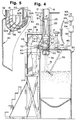
- the apparatus includes an enclosure or blade box, generally designated by reference numeral 12, for directing a bag 14 of particulate solid material 16 downwardly from an uppermost blade box opening 18 for engagement with a pair of slicing blades 20 and 22, each fixed to an opposed inner surface 24 or 25 of the blade box 12.
- the slicing blades 20 and 22 extend inwardly from the opposed inner surfaces 24 and 25, respectively, of the blade box 12, each beveled at 26 such that the beveled portions 26 of the opposed knife blades 20 and 22 lie in the same plane to achieve relatively dust-free and clean bag slicing.
- the slicing blades 20 and 22 extend downwardly and inwardly toward a transverse center of the enclosure or blade box 12 for gradually and cleanly slicing open the bag 14 of particulate material 16.
- the blades 20 and 22 may overlap at a transverse center 26, e.g. one half inch, to slice the bag into two halves.
- the bevel angle, ⁇ , (Fig. 3), of the blades 20 and 22 is not critical and the bevel generally is provided at an angle of about 30 to about 50°. As shown in Figure 2, the slicing blades 20 and 22 converge and meet at the transverse center of the blade box 12 to slice the bag 14 into two pieces.
- the opening 18 in the blade box 12 of the preferred embodiment is eight inches by twenty-seven and one half inches and each blade 20 and 22 is sixty inches long, five inches wide and one half inch thick, to provide an angle, ⁇ between the slicing blades 20 and 22 of about 8°. Best results are achieved with an acute angle, ⁇ , e.g. 5-30°, between the slicing blades 20 and 22.
- the slicing blades 20 and 22 are fixedly secured to inner opposed downwardly and inwardly inclined surfaces 24 and 25 of the enclosure or blade box 12 to slice open the bag 14 without any moving parts.
- the provision of slicing blades 20 and 22 fixed to interior opposed surfaces 24 and 25 of blade box 12 without moving mechanical parts is important to prevent the particulate material 16 from being caught between moving mechanical parts to make sure that the particulate material 16 within the bag 14 is completely emptied from the bag 14 and that all of the particulate material 16 proceeds downwardly into a holding tank 30 so that the amount or concentration of the particulate material 16 within the holding tank 30 is always known. This also greatly reduces the need for maintenance and the potential of toxic/chemical exposure.
- a downwardly angled perforated basket best shown in Figures 4 and 5, generally designated by reference numeral 32, is disposed beneath the slicing blades 20 and 22 such that an upper portion 34 of the perforated basket is mounted to the enclosure or blade box 12 and a lower, downwardly angled perforated bottom 36 of the basket 32 is disposed within the holding tank 30, extending within the holding tank 30 through a sealed upper opening 38 in an upper surface 40 of the holding tank 30.
- the downward angling of the bottom 36 of the basket 32 essentially empties the contents of the bag as the bag halves partially rotate during impact of one bag half on each side of the downwardly angled bottom 36 of basket 32.
- the perforated basket 32 is formed from a plurality of rods 33 that are secured together at points of intersection, such as by welding, to form two side walls 32A, and a back wall 32B, integral with the downwardly angled bottom wall or floor 36, leaving the top open for receiving a sliced bag, and leaving the front 42 open for a worker to grasp and rinse the inner surfaces of each bag, remove the bags and deposit the empty bags into a waste container or plastic tube 49, disposed proximate to the open front of basket 32.
- Each bag half contacts an opposite side wall 32A of basket 32 and each bag half rotates by gravity upon impact to substantially completely empty each bag half through the bottom wall 36 of basket 32.
- the basket 32 is disposed directly beneath the chute 12 and open at its top so that the basket 32 receives a sliced bag of material 14 that comes to rest on the downwardly angled floor 36.
- the open top of basket 32 is sized and shaped to correspond with a lower end of chute 12 so that all material 16 from bag 14 falls through the basket 32 and into the mixing tank 30.
- the round cross section of the rods 33 prevent any particulate material 16 from substantially adhering to the basket 32.
- a front portion of the basket 32 includes an open area 42 communicating with a glove box 48 adapted for manually grasping of the bag 14 and removal of solids from interior bag surfaces with a wash liquid or gas and for bag removal and disposal performed from an open front area 42 of the basket 32.
- a work station is disposed adjacent to the open area 42 of the perforated basket 32 for positioning a worker 46 within an environmentally safe glove box, generally designated by reference numeral 48, so that the worker 46 can rinse an interior surface of the bags 14, remove and dispose of the bags 14 through an adjacent, impervious disposal receptacle window 47, e.g.1 into an elongated plastic tube or bag 49, without contacting the particulate material 16.
- a metered water supply such as water from flexible hose 50, is disposed in close proximity to the perforated basket 32, outside of the glove box 48, and extends within the basket 32 for use by worker 46 to rinse the blades 20 and 22, interior surfaces 24 and 25 of the blade box 12, and metal rods 33 forming the basket 32.
- the glove box 48 includes a transparent wall 51 adjacent to and facing the open area 42 of the perforated basket 32 so that the worker 46 can insert his hands in flexible sleeves 52 and gloves 54, hermetically sealed to the transparent wall 51 for grasping, washing, and disposing of the washed bags 14 by inserting the rinsed bags 14 into the disposal bag 49 via window 47, without contacting the contents 16 of bag 14, after thoroughly washing the interior surfaces of the bags 14. If necessary, the worker 46 can also wash the interior of the blade box 12 and the slicing blades 20 and 22. All wash or rinse liquid falls into the holding vessel 30 together with all rinsed particulate material 16.
- the wash liquid supply hose 50 includes a remotely mounted meter (not shown) capable of measuring the amount of rinse liquid that passes through the hose 50 so that the operator 46 is, at all times, aware of the amount of rinse liquid falling by gravity into the holding vessel 30. In this manner, a precise and accurate determination of the concentration of particulate material 16 within the holding vessel 30 is known after rinsing of entrained particulate material is complete.
- a gas e.g. air, can be supplied from hose 50 for removal of solids from the interior bag surfaces and from the blade box 12 and the slicing blades 20 and 22.
- the glove box 48 is disposed to completely surround the basket 32 to prevent the escape of any particulate material into the surrounding atmosphere.
- a mixing blade 56 driven by motor 58 optionally extends into holding tank 30 for homogeneously mixing of solid materials with liquid in tank 30.
- a gas (via liquid media) scrubber 64 is mounted on the upper surface 40 of the holding vessel 30 in sealed, vapor communication with the interior of the holding vessel 30 via a conduit 62, and a blower or vapor pump 60, in vapor communication with a scrubber outlet 65, through a conduit 66, draws air through the bag feeding chute or blade box 12 and into the holding vessel 30 to maintain a negative pressure through the apparatus.
- Any toxic vapors that pass into the scrubber 64 are neutralized, e.g., with sodium metabisulfite, and non-toxic vapors proceed through a blower outlet conduit 68 to the atmosphere.
- the method and apparatus are equally applicable to debagging materials that are kept dry, such as sugar, flour and other dusty materials whether or not the materials are hazardous or toxic.
- debagging materials such as sugar, flour and other dusty materials whether or not the materials are hazardous or toxic.
- entrained solids can be blown from the blade box 12, the blades 20 and 22 and from the rods 33 forming the basket 32 using compressed air or other pressurized gas instead of using a water wash.
- the dust then can be collected in a standard dry dust filtering media, as is well known in the art.
Abstract
Description
- The present invention is directed to a method and apparatus for debagging dust-containing or hazardous materials, including method and apparatus for removing solid material from interior surfaces of a bag for complete removal of the contents of the bag and directing all of the bag contents into a holding tank. More particularly, the present invention is directed to a method and apparatus for removing dust-containing or hazardous material from a disposable bag by dropping the bag down a vertical bag-feeding chute that includes one or more fixed knife blades for slicing open the bag without knife blade movement; catching the sliced bag on a perforated receiving basket disposed above a solid or liquid level in a holding or mixing tank so that most of the contents drop downwardly into the holding tank; and washing or blowing entrained material from interior surfaces of the sliced bag and chute so that both the entrained material and any wash liquid used are directed into the mixing tank. When wash liquid is used, the amount of wash liquid can be metered to obtain a precise and relatively accurate determination of the final concentration of the debagged material in the liquid combined therewith in the mixing tank.
- It is well known to provide apparatus capable of opening and substantially emptying bags of particulate, powdered or pulverulent materials particularly for toxic or hazardous materials, to aid in the speed of production in a process using such materials, and especially for debagging hazardous materials to prevent or minimize human contact during operation and mechanical maintenance with the contents of the bag and to attempt to remove all of the material from the bag. Examples of patents directed to mechanical debagging apparatus are as follows: 2,107,995, Statham, et al., 2,706,567, Luna, et al.; 3,145,858, Helbig; 3,482,718, Moriarty; 3,739,471, Peres; 4,034,877, Bennison; 4,252,489, Mechalas; 4,289, 438, Murer; 4,627,781, Borgner; 4,798,508, Lewis.
- While the apparatus described in the above-identified patents are useful for debagging and removing most dust-containing and hazardous substances, such apparatus suffers from one or more of the following disadvantages: debagging apparatus used for debagging toxic and hazardous materials should not have a bag opening means that includes moving parts since some of the toxic or hazardous material may become clogged in an area of mechanical movement during operation, making operation and maintenance hazardous; many of the above-described debagging apparatus do not include a rinsing mechanism whereby dust-containing or hazardous materials remaining or entrained within the bag after substantially complete emptying can be carefully rinsed by hand, applying liquid essentially only to interior, usually plastic-lined surfaces of the bag to ensure that essentially all of the bagged material is rinsed from the bag and directed, together with rinse liquid, into a mixing tank without absorption of water-soluble material and rinse water onto an absorbent exterior bag surface; and the above-described apparatus do not include a metered wash liquid supply such that by rinsing an interior surface of the bag with rinse liquid, essentially all of the rinsed bag contents, as well as a known quantity of rinse liquid, are directed into a mixing tank for further processing. These and other disadvantages of prior art bag opening and emptying apparatus have been overcome in accordance with the method and apparatus of the present invention.
- In brief, the method and apparatus of the present invention remove dust-containing or hazardous material from bags, and include a vertical bag feeding chute having one or more vertically disposed knife blades fixed in the chute to slice open the bag as it falls through the chute. The sliced bag is caught in a downwardly angled perforated basket disposed below the bag feeding chute where an operator removes solid material from the interior of the sliced bag with a fluid (liquid or gas) after most of the bag contents have fallen through the perforated receiving basket and into a mixing tank. Any wash liquid used can be metered so that the amount of wash liquid used (1) for rinsing entrained material from the interior surfaces of the bag and perforated basket and (2) for washing the inner surfaces of the bag feeding chute, including knife blades, is measured on each occasion so that the concentration of the bag contents in the mixing tank is always known. While the apparatus and method of the present invention are particularly useful for debagging acrylamide monomer in the production of polyacrylamide homopolymers and copolymers, the method and apparatus are useful for debagging, and optionally mixing with liquid, any bagged, dust-containing, hazardous or toxic solid material.
- Accordingly, one aspect of the present invention is to provide a method and apparatus for debagging dust-containing, toxic or hazardous solid materials including removing solid material from an interior surface of the bag with a fluid while directing the bag contents into a holding vessel.
- Another aspect of the present invention is to provide a method and apparatus for debagging dust-containing, toxic or hazardous material without human contact of the debagged material using fixed knife blades, providing a very greatly reduced maintenance exposure (no moving parts) in a bag-receiving chute disposed above a holding tank, while maintaining a negative pressure through the chute and holding tank, and including a glove-box worker station adapted for manual removal of solid material from interior bag surfaces with a fluid so that entrained material falls vertically by gravity into a mixing vessel.
- Still another aspect of the present invention is to maintain a negative pressure within a chute and holding tank to ensure all freely dispersed dust in the air will be drawn into the chute and holding tank. Air drawn out of the apparatus to generate the negative pressure is passed through a wet scrubber device.
- The above and other aspects and advantages of the present invention will become apparent from the following detailed description of the preferred embodiments of the present invention taken in conjunction with the drawings.
-
- Figure 1 is a perspective view of the apparatus of the present invention;
- Figure 2 is a side view of the apparatus of Figure 1 taken along the line 2-2 of Figure 1;
- Figure 3 is a top view of the blade box portion of the apparatus taken along the line 3-3 of Figure 2;
- Figure 4 is a side view of the apparatus of Figure 1, similar to Figure 2, showing a worker stationed in a glove box for rinsing the interior of sliced bags, rinsing the apparatus, and disposing of the bags; and
- Figure 5 is a more detailed, partially broken-away view of a perforated, bag-receiving basket portion of the apparatus of the present invention.
- Turning now to the drawings and initially to Figures 1 and 2, there is shown an apparatus for debagging dust-containing or hazardous materials generally designated by
reference numeral 10. The apparatus includes an enclosure or blade box, generally designated byreference numeral 12, for directing abag 14 of particulatesolid material 16 downwardly from an uppermost blade box opening 18 for engagement with a pair ofslicing blades inner surface blade box 12. As best shown in Figure 3, theslicing blades inner surfaces blade box 12, each beveled at 26 such that thebeveled portions 26 of theopposed knife blades slicing blades blade box 12 for gradually and cleanly slicing open thebag 14 ofparticulate material 16. Theblades transverse center 26, e.g. one half inch, to slice the bag into two halves. The bevel angle, α, (Fig. 3), of theblades slicing blades blade box 12 to slice thebag 14 into two pieces. As shown in the drawings, theopening 18 in theblade box 12 of the preferred embodiment is eight inches by twenty-seven and one half inches and eachblade slicing blades slicing blades - In accordance with an important feature of the present invention, the
slicing blades inclined surfaces blade box 12 to slice open thebag 14 without any moving parts. The provision of slicingblades opposed surfaces blade box 12 without moving mechanical parts is important to prevent theparticulate material 16 from being caught between moving mechanical parts to make sure that theparticulate material 16 within thebag 14 is completely emptied from thebag 14 and that all of theparticulate material 16 proceeds downwardly into aholding tank 30 so that the amount or concentration of theparticulate material 16 within theholding tank 30 is always known. This also greatly reduces the need for maintenance and the potential of toxic/chemical exposure. - A downwardly angled perforated basket best shown in Figures 4 and 5, generally designated by
reference numeral 32, is disposed beneath theslicing blades upper portion 34 of the perforated basket is mounted to the enclosure orblade box 12 and a lower, downwardly angledperforated bottom 36 of thebasket 32 is disposed within theholding tank 30, extending within theholding tank 30 through a sealedupper opening 38 in anupper surface 40 of theholding tank 30. The downward angling of thebottom 36 of thebasket 32 essentially empties the contents of the bag as the bag halves partially rotate during impact of one bag half on each side of the downwardlyangled bottom 36 ofbasket 32. - After the
bag 14 is sliced open by theslicing blades bag 14, together with theparticulate material 16, proceeds downwardly by gravity toward the downwardlyangled bottom 36 of the perforatedbasket 32. The perforatedbasket 32 is formed from a plurality ofrods 33 that are secured together at points of intersection, such as by welding, to form twoside walls 32A, and aback wall 32B, integral with the downwardly angled bottom wall orfloor 36, leaving the top open for receiving a sliced bag, and leaving thefront 42 open for a worker to grasp and rinse the inner surfaces of each bag, remove the bags and deposit the empty bags into a waste container orplastic tube 49, disposed proximate to the open front ofbasket 32. Each bag half contacts anopposite side wall 32A ofbasket 32 and each bag half rotates by gravity upon impact to substantially completely empty each bag half through thebottom wall 36 ofbasket 32. Thebasket 32 is disposed directly beneath thechute 12 and open at its top so that thebasket 32 receives a sliced bag ofmaterial 14 that comes to rest on the downwardlyangled floor 36. The open top ofbasket 32 is sized and shaped to correspond with a lower end ofchute 12 so that allmaterial 16 frombag 14 falls through thebasket 32 and into themixing tank 30. The round cross section of therods 33 prevent anyparticulate material 16 from substantially adhering to thebasket 32. - The perforations within the downwardly
angled bottom 36 ofbasket 32 are sufficiently large such that the particulate and compactedmaterial 16 passes through theangled bottom 36 of thebasket 32; the impact breaks up relatively large agglomerates of material into smaller lumps; and the perforations are sufficiently small such that thebag 14 is retained by thebasket 32 for manual solids removal and disposal, as will be described in more detail hereinafter. As best shown in Figures 4 and 5, a front portion of thebasket 32 includes anopen area 42 communicating with aglove box 48 adapted for manually grasping of thebag 14 and removal of solids from interior bag surfaces with a wash liquid or gas and for bag removal and disposal performed from anopen front area 42 of thebasket 32. - In accordance with an important feature of the present invention, a work station, generally designated by
reference numeral 44, is disposed adjacent to theopen area 42 of the perforatedbasket 32 for positioning aworker 46 within an environmentally safe glove box, generally designated byreference numeral 48, so that theworker 46 can rinse an interior surface of thebags 14, remove and dispose of thebags 14 through an adjacent, imperviousdisposal receptacle window 47, e.g.1 into an elongated plastic tube orbag 49, without contacting theparticulate material 16. - In accordance with another feature of one embodiment of the present invention, a metered water supply, such as water from
flexible hose 50, is disposed in close proximity to theperforated basket 32, outside of theglove box 48, and extends within thebasket 32 for use byworker 46 to rinse theblades interior surfaces blade box 12, andmetal rods 33 forming thebasket 32. Theglove box 48 includes atransparent wall 51 adjacent to and facing theopen area 42 of the perforatedbasket 32 so that theworker 46 can insert his hands inflexible sleeves 52 andgloves 54, hermetically sealed to thetransparent wall 51 for grasping, washing, and disposing of the washedbags 14 by inserting the rinsedbags 14 into thedisposal bag 49 viawindow 47, without contacting thecontents 16 ofbag 14, after thoroughly washing the interior surfaces of thebags 14. If necessary, theworker 46 can also wash the interior of theblade box 12 and theslicing blades holding vessel 30 together with all rinsedparticulate material 16. The washliquid supply hose 50 includes a remotely mounted meter (not shown) capable of measuring the amount of rinse liquid that passes through thehose 50 so that theoperator 46 is, at all times, aware of the amount of rinse liquid falling by gravity into theholding vessel 30. In this manner, a precise and accurate determination of the concentration ofparticulate material 16 within theholding vessel 30 is known after rinsing of entrained particulate material is complete. Alternatively, if the solid material is not combined with liquid, a gas, e.g. air, can be supplied fromhose 50 for removal of solids from the interior bag surfaces and from theblade box 12 and theslicing blades - As best shown in Figures 1 and 4, the
glove box 48 is disposed to completely surround thebasket 32 to prevent the escape of any particulate material into the surrounding atmosphere. A mixingblade 56 driven bymotor 58 optionally extends intoholding tank 30 for homogeneously mixing of solid materials with liquid intank 30. - As best shown in Figures 2 and 4, a gas (via liquid media)
scrubber 64 is mounted on theupper surface 40 of theholding vessel 30 in sealed, vapor communication with the interior of theholding vessel 30 via aconduit 62, and a blower orvapor pump 60, in vapor communication with ascrubber outlet 65, through aconduit 66, draws air through the bag feeding chute orblade box 12 and into theholding vessel 30 to maintain a negative pressure through the apparatus. Any toxic vapors that pass into thescrubber 64 are neutralized, e.g., with sodium metabisulfite, and non-toxic vapors proceed through a blower outlet conduit 68 to the atmosphere. - While the preferred embodiment of the present invention has been described with reference to the debagged material falling into a liquid holding or mixing
tank 30, the method and apparatus are equally applicable to debagging materials that are kept dry, such as sugar, flour and other dusty materials whether or not the materials are hazardous or toxic. In the case of dry materials, entrained solids can be blown from theblade box 12, theblades rods 33 forming thebasket 32 using compressed air or other pressurized gas instead of using a water wash. The dust then can be collected in a standard dry dust filtering media, as is well known in the art. - It should be understood that the present disclosure has been made only by way of the preferred embodiment and that numerous changes in details of construction, combination and arrangement of parts can be resorted to without departing from the spirit and scope of the invention as hereunder claimed.
Claims (12)
- Apparatus for removing dust-containing or hazardous material from bags comprising(a) a vertical bag feeding chute including at least one vertically disposed knife blade fixed in said chute to slice open said bag as it falls through said chute;(b) a perforated receiving basket disposed below said bag feeding chute to receive said blade-sliced bag; and(c) a holding tank disposed below said receiving basket for receiving the contents of said bag.
- The apparatus of claim 1 further including:(d) wash liquid supply means for washing said bag feeding chute, said receiving basket and said slit bag while directing said wash liquid and material washed from the interior of said slit bag into said holding tank to control the concentration of said liquid/solid mixture therein; and(e) means for determining the amount of wash liquid supply directed into said holding tank.
- Apparatus according to claim 1 further including means for maintaining a negative pressure within said apparatus to eliminate dust generation around the apparatus, wherein preferably the negative pressure maintaining means comprises a blower in fluid communication with the holding tank for the downward flow of gas through the feeding chute, basket and out of the mixing tank, and preferably further including a scrubber in fluid communication with the negative pressure maintaining means for removing contaminants from gas removed from the apparatus by the negative pressure maintaining means.
- Apparatus according to claim 1 further including a glove box for protecting a worker from the contents of said bags.
- Apparatus according to claim 1, wherein said receiving basket includes a downwardly angled perforated bottom such that the basket facilitates discharge of the open bag sections to aid in emptying the contents of said bag.
- Apparatus of claim 1, wherein said knife blades slice said bags without knife blade movement.
- A method for directing dusty or hazardous solid material into a holding vessel from bags containing said material comprising guiding a bag containing dusty or hazardous solid material into an essentially vertical bag feeding chute, said chute including, on an interior surface thereof, a knife blade adapted to cleanly slit open said bag, substantially without generating bag particles, as said bag falls through said chute;
causing the slit-open bag and its contents to drop from said chute onto a perforated bag-receiving basket;
separating the slit open bag from its solid contents in the receiving basket;
contacting the inside of said separated, slit-open bag with a pressurized fluid while allowing the solid material to fall through said perforated receiving basket;
directing the solid material from the bag into a holding tank; and
removing the opened bag from the bag-receiving basket, wherein the pressurized fluid is preferably compressed air having a pressure greater than ambient pressure. - A method according to claim 7 further including establishing a negative pressure through the chute and holding tank to eliminate dust generation surrounding the apparatus wherein the negative pressure is preferably established by operating a blower in fluid communication with a scrubber and holding tank for pulling gas downwardly through the feeding chute, and out of the holding tank.
- A method according to claim 7 further including removing slit bags through a glove box to protect a worker from the contents of said bags.
- A method according to claim 7 further including neutralizing contaminants carried by gas within the apparatus in a scrubber in fluid communication with the holding tank.
- A method according to claim 7 further including directing the slit bag from the fixed knife blades onto a downwardly angled perforated basket such that the basket facilitates discharge of the open bag sections to aid in emptying the contents of said bag.
- A method according to claim 7, wherein the bagged material is fed from the bags to the holding vessel without liquid addition.
Applications Claiming Priority (2)
| Application Number | Priority Date | Filing Date | Title |
|---|---|---|---|
| US07/719,168 US5222511A (en) | 1991-06-27 | 1991-06-27 | Apparatus for debagging dust-containing or hazardous materials |
| US719168 | 1991-06-27 |
Publications (2)
| Publication Number | Publication Date |
|---|---|
| EP0520183A1 true EP0520183A1 (en) | 1992-12-30 |
| EP0520183B1 EP0520183B1 (en) | 1996-01-03 |
Family
ID=24889017
Family Applications (1)
| Application Number | Title | Priority Date | Filing Date |
|---|---|---|---|
| EP92108408A Expired - Lifetime EP0520183B1 (en) | 1991-06-27 | 1992-05-19 | Method and apparatus for debagging dust-containing or hazardous materials |
Country Status (7)
| Country | Link |
|---|---|
| US (1) | US5222511A (en) |
| EP (1) | EP0520183B1 (en) |
| JP (1) | JPH06211222A (en) |
| AT (1) | ATE132450T1 (en) |
| CA (1) | CA2046200C (en) |
| DE (1) | DE69207281T2 (en) |
| ES (1) | ES2081515T3 (en) |
Cited By (1)
| Publication number | Priority date | Publication date | Assignee | Title |
|---|---|---|---|---|
| EP1918209A1 (en) | 2006-10-31 | 2008-05-07 | Hecht Anlagenbau GmbH | Method for operating a packaging emptying station |
Families Citing this family (7)
| Publication number | Priority date | Publication date | Assignee | Title |
|---|---|---|---|---|
| NZ540013A (en) * | 2005-08-12 | 2007-05-31 | Powder Projects Ltd | Powder handling device |
| JP5554504B2 (en) * | 2009-03-02 | 2014-07-23 | ニチアス株式会社 | Waste volume reduction device |
| FR2996212B1 (en) * | 2012-10-01 | 2014-10-10 | Spcm Sa | INSTALLATION FOR EMPTYING BAGS OF PULVERULENT PRODUCTS AND METHOD IMPLEMENTING THE INSTALLATION |
| US10029258B2 (en) | 2015-03-31 | 2018-07-24 | Pentair Flow Technologies, Llc | Closed system chemical handling and delivery system and method |
| JP6435252B2 (en) * | 2015-10-13 | 2018-12-05 | 株式会社冨士機 | Bag unpacking apparatus and method |
| CN110844229A (en) * | 2019-11-27 | 2020-02-28 | 苏州贝爱特自动化科技有限公司 | Film tearing light guide body pressing equipment and method |
| CN114275267A (en) * | 2021-12-17 | 2022-04-05 | 蒙仲勤 | Dust collecting equipment for building cement |
Citations (2)
| Publication number | Priority date | Publication date | Assignee | Title |
|---|---|---|---|---|
| US2818985A (en) * | 1951-01-06 | 1958-01-07 | Nat Tea Packing Company Inc | Apparatus for reclaiming contents of filled envelope packages |
| FR1463137A (en) * | 1965-11-09 | 1966-06-03 | Orval Manutention | Improvements to processes and devices for opening and emptying bags |
Family Cites Families (19)
| Publication number | Priority date | Publication date | Assignee | Title |
|---|---|---|---|---|
| US2107995A (en) * | 1937-02-19 | 1938-02-08 | West Virginia Pulp & Paper Co | Dustless bag discharge hopper |
| US2706567A (en) * | 1953-07-22 | 1955-04-19 | George A Sherman | Combined seal and bag emptying device |
| US3145858A (en) * | 1962-10-17 | 1964-08-25 | Atlas Chem Ind | Bag opening device |
| US3482718A (en) * | 1968-02-07 | 1969-12-09 | Edward J Moriarty | Bag opening and emptying machine |
| US3739471A (en) * | 1971-06-17 | 1973-06-19 | Peres Electronic Machines | Apparatus for automatically opening and emptying containers into a blending tank |
| US4034877A (en) * | 1975-09-02 | 1977-07-12 | Bel-Tyne Company Limited | Apparatus for opening containers |
| FR2416182A1 (en) * | 1978-02-06 | 1979-08-31 | Colinet Const Mec | MECHANICAL OPENING AND EMPTYING MACHINE FOR BAGS MAY CONTAIN A TOXIC PRODUCT |
| US4252489A (en) * | 1979-04-04 | 1981-02-24 | Emmanuel Mechalas | Bag opening apparatus |
| JPS5828003A (en) * | 1981-08-13 | 1983-02-18 | Aisin Seiki Co Ltd | Actuator |
| US4440185A (en) * | 1982-08-18 | 1984-04-03 | Wiltse Dean P | Support stand for a food slicer |
| JPS59134137A (en) * | 1983-01-21 | 1984-08-01 | ライト工業株式会社 | Method and device for opening bag of bag packing |
| JPS59221231A (en) * | 1983-05-31 | 1984-12-12 | 日本ペイント株式会社 | Automatic bag disassembling machine |
| DE3340894A1 (en) * | 1983-11-11 | 1985-05-23 | Luco-Technic Gmbh Verfahrenstechnische Anlagen, 6474 Ortenberg | BAG CUTTING AND EMPTYING DEVICE WITH CONNECTED COLLECTED DEDUSTING FILTER |
| US4993199A (en) * | 1987-03-30 | 1991-02-19 | Container Products Corporation | Portable self-contained decontamination booth |
| US4928440A (en) * | 1987-03-30 | 1990-05-29 | Container Products Corp. | Decontamination booth |
| US4798508A (en) * | 1988-03-25 | 1989-01-17 | The Dow Chemical Company | Machine and method for opening a filled bag, emptying the bag, and disposing of the empty bag |
| US5097750A (en) * | 1989-01-13 | 1992-03-24 | Lab Products, Inc. | Waste management disposal system |
| US5095925A (en) * | 1989-03-13 | 1992-03-17 | Elledge David M | Aseptic cleaning apparatus |
| US5062871A (en) * | 1989-11-13 | 1991-11-05 | Seth C. Hunt | System for localizing a portion of a structure for treatment |
-
1991
- 1991-06-27 US US07/719,168 patent/US5222511A/en not_active Expired - Fee Related
- 1991-07-04 CA CA002046200A patent/CA2046200C/en not_active Expired - Fee Related
-
1992
- 1992-05-19 DE DE69207281T patent/DE69207281T2/en not_active Expired - Fee Related
- 1992-05-19 AT AT92108408T patent/ATE132450T1/en not_active IP Right Cessation
- 1992-05-19 EP EP92108408A patent/EP0520183B1/en not_active Expired - Lifetime
- 1992-05-19 ES ES92108408T patent/ES2081515T3/en not_active Expired - Lifetime
- 1992-06-19 JP JP4184734A patent/JPH06211222A/en active Pending
Patent Citations (2)
| Publication number | Priority date | Publication date | Assignee | Title |
|---|---|---|---|---|
| US2818985A (en) * | 1951-01-06 | 1958-01-07 | Nat Tea Packing Company Inc | Apparatus for reclaiming contents of filled envelope packages |
| FR1463137A (en) * | 1965-11-09 | 1966-06-03 | Orval Manutention | Improvements to processes and devices for opening and emptying bags |
Cited By (3)
| Publication number | Priority date | Publication date | Assignee | Title |
|---|---|---|---|---|
| EP1918209A1 (en) | 2006-10-31 | 2008-05-07 | Hecht Anlagenbau GmbH | Method for operating a packaging emptying station |
| US7587882B2 (en) | 2006-10-31 | 2009-09-15 | Hecht Anlagenbau Gmbh | Method for the operation of a package emptying station |
| US7827770B2 (en) | 2006-10-31 | 2010-11-09 | Hecht Technologie Gmbh | Method for the operation of a package emptying station |
Also Published As
| Publication number | Publication date |
|---|---|
| CA2046200C (en) | 1995-02-07 |
| CA2046200A1 (en) | 1992-12-28 |
| ATE132450T1 (en) | 1996-01-15 |
| DE69207281D1 (en) | 1996-02-15 |
| EP0520183B1 (en) | 1996-01-03 |
| DE69207281T2 (en) | 1996-07-04 |
| ES2081515T3 (en) | 1996-03-16 |
| US5222511A (en) | 1993-06-29 |
| JPH06211222A (en) | 1994-08-02 |
Similar Documents
| Publication | Publication Date | Title |
|---|---|---|
| US5092527A (en) | Fluorescent tube crusher with particulate separation and recovery | |
| US5042724A (en) | Fluorescent tube crusher with particulate separation and recovery | |
| US5613824A (en) | Automatic bag opening device | |
| CA2046200C (en) | Method and apparatus for debagging dust-containing or hazardous materials | |
| US6202278B1 (en) | Apparatus for automatic plug removal and method therefor | |
| CN105478203B (en) | A kind of powder package bag crusberscreen | |
| EP0130747A2 (en) | Removal of airborne contaminant | |
| US4759508A (en) | Apparatus for crushing containers containing a toxic liquid | |
| US5368652A (en) | Method for purging and decontaminating a product-containing storage drum | |
| DE102013011758A1 (en) | Device for extracting and filtering fine dust polluted air | |
| US4455222A (en) | Flux recovery device | |
| US3145858A (en) | Bag opening device | |
| JPH04352694A (en) | Device for opening and emtying strong, deformable collecting body or flexible bag | |
| US5026432A (en) | Method and apparatus for removing and disposing of contaminated concrete | |
| JPH079436A (en) | Kneading method and compounding chemical recovery device | |
| US4822430A (en) | Method and apparatus for cleaning boiler burners | |
| JP2603163B2 (en) | Vibration feeder with disposable hopper | |
| JP4577476B2 (en) | Continuous automatic cleaning equipment for chemical containers | |
| JP2000079921A (en) | Bag opener for flexible container bag | |
| CN218502184U (en) | Clothing waste cloth processing apparatus | |
| JP2005103379A (en) | Suction device and separator for suction device | |
| CN212654669U (en) | Gravity type soft bag opener | |
| JPH06123681A (en) | Automatic sampling device, hopper device, receiver washing device, hopper washing device, and receiver carrying device | |
| JP2960643B2 (en) | Decontamination hood equipment for dry ice blast | |
| JPS639415Y2 (en) |
Legal Events
| Date | Code | Title | Description |
|---|---|---|---|
| PUAI | Public reference made under article 153(3) epc to a published international application that has entered the european phase |
Free format text: ORIGINAL CODE: 0009012 |
|
| AK | Designated contracting states |
Kind code of ref document: A1 Designated state(s): AT BE CH DE ES FR GB IT LI NL |
|
| 17P | Request for examination filed |
Effective date: 19930223 |
|
| 17Q | First examination report despatched |
Effective date: 19940630 |
|
| GRAA | (expected) grant |
Free format text: ORIGINAL CODE: 0009210 |
|
| AK | Designated contracting states |
Kind code of ref document: B1 Designated state(s): AT BE CH DE ES FR GB IT LI NL |
|
| REF | Corresponds to: |
Ref document number: 132450 Country of ref document: AT Date of ref document: 19960115 Kind code of ref document: T |
|
| ITF | It: translation for a ep patent filed |
Owner name: SOCIETA' ITALIANA BREVETTI S.P.A. |
|
| REF | Corresponds to: |
Ref document number: 69207281 Country of ref document: DE Date of ref document: 19960215 |
|
| REG | Reference to a national code |
Ref country code: CH Ref legal event code: NV Representative=s name: DIPL.-ING. ETH H. R. WERFFELI PATENTANWALT |
|
| REG | Reference to a national code |
Ref country code: ES Ref legal event code: FG2A Ref document number: 2081515 Country of ref document: ES Kind code of ref document: T3 |
|
| ET | Fr: translation filed | ||
| PG25 | Lapsed in a contracting state [announced via postgrant information from national office to epo] |
Ref country code: GB Effective date: 19960519 Ref country code: AT Effective date: 19960519 |
|
| PG25 | Lapsed in a contracting state [announced via postgrant information from national office to epo] |
Ref country code: ES Free format text: LAPSE BECAUSE OF NON-PAYMENT OF DUE FEES Effective date: 19960520 |
|
| PG25 | Lapsed in a contracting state [announced via postgrant information from national office to epo] |
Ref country code: LI Effective date: 19960531 Ref country code: CH Effective date: 19960531 Ref country code: BE Effective date: 19960531 |
|
| PLBE | No opposition filed within time limit |
Free format text: ORIGINAL CODE: 0009261 |
|
| STAA | Information on the status of an ep patent application or granted ep patent |
Free format text: STATUS: NO OPPOSITION FILED WITHIN TIME LIMIT |
|
| BERE | Be: lapsed |
Owner name: DIATEC ENVIRONMENTAL Effective date: 19960531 |
|
| PG25 | Lapsed in a contracting state [announced via postgrant information from national office to epo] |
Ref country code: NL Effective date: 19961201 |
|
| 26N | No opposition filed | ||
| GBPC | Gb: european patent ceased through non-payment of renewal fee |
Effective date: 19960519 |
|
| REG | Reference to a national code |
Ref country code: CH Ref legal event code: PL |
|
| PG25 | Lapsed in a contracting state [announced via postgrant information from national office to epo] |
Ref country code: FR Effective date: 19970131 |
|
| PG25 | Lapsed in a contracting state [announced via postgrant information from national office to epo] |
Ref country code: DE Effective date: 19970201 |
|
| NLV4 | Nl: lapsed or anulled due to non-payment of the annual fee |
Effective date: 19961201 |
|
| REG | Reference to a national code |
Ref country code: FR Ref legal event code: ST |
|
| REG | Reference to a national code |
Ref country code: ES Ref legal event code: FD2A Effective date: 19970611 |
|
| PG25 | Lapsed in a contracting state [announced via postgrant information from national office to epo] |
Ref country code: IT Free format text: LAPSE BECAUSE OF NON-PAYMENT OF DUE FEES Effective date: 20050519 |