EP0520100B1 - Integrated two reaction zone process for C4, C5 and C6 isomerization - Google Patents
Integrated two reaction zone process for C4, C5 and C6 isomerization Download PDFInfo
- Publication number
- EP0520100B1 EP0520100B1 EP91305685A EP91305685A EP0520100B1 EP 0520100 B1 EP0520100 B1 EP 0520100B1 EP 91305685 A EP91305685 A EP 91305685A EP 91305685 A EP91305685 A EP 91305685A EP 0520100 B1 EP0520100 B1 EP 0520100B1
- Authority
- EP
- European Patent Office
- Prior art keywords
- isomerization
- hydrogen
- feedstock
- stream
- zone
- Prior art date
- Legal status (The legal status is an assumption and is not a legal conclusion. Google has not performed a legal analysis and makes no representation as to the accuracy of the status listed.)
- Expired - Lifetime
Links
Images

Classifications
-
- C—CHEMISTRY; METALLURGY
- C07—ORGANIC CHEMISTRY
- C07C—ACYCLIC OR CARBOCYCLIC COMPOUNDS
- C07C5/00—Preparation of hydrocarbons from hydrocarbons containing the same number of carbon atoms
- C07C5/22—Preparation of hydrocarbons from hydrocarbons containing the same number of carbon atoms by isomerisation
- C07C5/27—Rearrangement of carbon atoms in the hydrocarbon skeleton
- C07C5/2767—Changing the number of side-chains
- C07C5/277—Catalytic processes
- C07C5/2791—Catalytic processes with metals
-
- C—CHEMISTRY; METALLURGY
- C07—ORGANIC CHEMISTRY
- C07C—ACYCLIC OR CARBOCYCLIC COMPOUNDS
- C07C5/00—Preparation of hydrocarbons from hydrocarbons containing the same number of carbon atoms
- C07C5/22—Preparation of hydrocarbons from hydrocarbons containing the same number of carbon atoms by isomerisation
- C07C5/27—Rearrangement of carbon atoms in the hydrocarbon skeleton
- C07C5/2702—Catalytic processes not covered by C07C5/2732 - C07C5/31; Catalytic processes covered by both C07C5/2732 and C07C5/277 simultaneously
- C07C5/2724—Catalytic processes not covered by C07C5/2732 - C07C5/31; Catalytic processes covered by both C07C5/2732 and C07C5/277 simultaneously with metals
-
- C—CHEMISTRY; METALLURGY
- C07—ORGANIC CHEMISTRY
- C07C—ACYCLIC OR CARBOCYCLIC COMPOUNDS
- C07C9/00—Aliphatic saturated hydrocarbons
-
- C—CHEMISTRY; METALLURGY
- C10—PETROLEUM, GAS OR COKE INDUSTRIES; TECHNICAL GASES CONTAINING CARBON MONOXIDE; FUELS; LUBRICANTS; PEAT
- C10L—FUELS NOT OTHERWISE PROVIDED FOR; NATURAL GAS; SYNTHETIC NATURAL GAS OBTAINED BY PROCESSES NOT COVERED BY SUBCLASSES C10G, C10K; LIQUEFIED PETROLEUM GAS; ADDING MATERIALS TO FUELS OR FIRES TO REDUCE SMOKE OR UNDESIRABLE DEPOSITS OR TO FACILITATE SOOT REMOVAL; FIRELIGHTERS
- C10L1/00—Liquid carbonaceous fuels
- C10L1/04—Liquid carbonaceous fuels essentially based on blends of hydrocarbons
- C10L1/06—Liquid carbonaceous fuels essentially based on blends of hydrocarbons for spark ignition
-
- Y—GENERAL TAGGING OF NEW TECHNOLOGICAL DEVELOPMENTS; GENERAL TAGGING OF CROSS-SECTIONAL TECHNOLOGIES SPANNING OVER SEVERAL SECTIONS OF THE IPC; TECHNICAL SUBJECTS COVERED BY FORMER USPC CROSS-REFERENCE ART COLLECTIONS [XRACs] AND DIGESTS
- Y02—TECHNOLOGIES OR APPLICATIONS FOR MITIGATION OR ADAPTATION AGAINST CLIMATE CHANGE
- Y02P—CLIMATE CHANGE MITIGATION TECHNOLOGIES IN THE PRODUCTION OR PROCESSING OF GOODS
- Y02P20/00—Technologies relating to chemical industry
- Y02P20/10—Process efficiency
Definitions
- This invention relates generally to the isomerization of hydrocarbons. This invention relates more specifically to the isomerization of C4, C5 and C6 cyclic hydrocarbons using a solid catalyst.
- a gasoline blending pool normally included C4 and heavier hydrocarbons having boiling points of less than 205°C (400°F) at atmospheric pressure.
- This range of hydrocarbon includes C4-C6 paraffins and especially the C5 and C6 normal paraffins which have relatively low octane numbers.
- the C4-C6 hydrocarbons have the greatest susceptibility to octane improvement by lead addition and were formerly upgraded in this manner.
- Octane improvement can also be obtained by using isomerization to rearrange the structure of the paraffinic hydrocarbons into branch-chained paraffins or reforming to convert the C6 and heavier hydrocarbons to aromatic compounds.
- the isomerization of paraffins is a reversible first order reaction.
- the reaction is limited by thermodynamic equilibrium. It has been generally found that lower temperatures shift the equilibrium of C5 and C6 hydrocarbons toward higher isoparaffin to normal paraffin ratios. These temperatures are typically in the range of 105-180°C (200-355°F). When isomerizing butane, its refractory nature demands somewhat higher temperatures usually greater than 170°C (340°F) to obtain high equilibrium ratios of isobutane to butane.
- a number of catalyst systems have been used in effecting isomerization reactions.
- Traditional catalyst systems are a hydrochloric acid promoted aluminum chloride system and a supported aluminum chloride catalyst.
- Recently zeolite catalysts, particularly mordenite, are also finding increased usage due to their decreased sensitivity to sulfur and water.
- a platinum group metal is usually incorporated into both catalysts. All of these catalyst systems are very reactive and can generate undesirable side reactions such as disproportionation and cracking. These side reactions not only decrease the product yield but can form olefinic fragments that combine with the catalyst and shorten its life.
- One commonly practiced method of controlling these undesired reactions has been to carry out the reaction in the presence of hydrogen. However, high concentrations of hydrogen and high molecular weight species tend to inhibit the butane isomerization reactions.
- U.S. Patent 3,242,228 issued to Riordan et al. teaches an isomerization catalyst consisting of an alumina base with 0.01 to 1.0 wt.% platinum, and 2.5 to 7.0 wt.% chlorine.
- the catalyst is used at process conditions including a liquid hourly space velocity (LHSV) of from 0.5 to 2.0 hr. ⁇ 1, a hydrogen to hydrocarbon mole ratio within the range of from 0.1:1 to 5.0:1, and a temperature of 150-200°C (300-390°F) for butane isomerization, or a temperature of 120-160°C (250-320°F) for C5-C6 isomerization.
- LHSV liquid hourly space velocity
- U.S. Patent 3,789,082 is directed to a method for practicing low temperature isomerization using a chlorided platinum-alumina catalyst.
- the process operates in the presence of a hydrogen chloride promoter in an amount up to 0.1 to 5 wt.% of the feedstock and temperatures in the range of 100-200°C (210-390°F) for the isomerization of feedstreams comprising C4 and/or C5 and/or C6 fractions.
- U. S. Patent 4,804,803 discloses a process for the isomerization of C4-C6 paraffins that uses a highly active chlorided, platinum alumina catalyst to carry out the process with a hydrogen to hydrocarbon ratio of 0.05 or less in the effluent from the isomerization zone.
- This invention is a process for the isomerization of a C4 feedstock and a C5-C6 feedstock that reduces equipment and operating expenses by utilizing a process flow scheme that provides beneficial heat integration and facilitates the use of common recovery zone while permitting a wide variation in the relative ratio of the C4 to the C5-C6 feedstock.
- the isomerization of the C4 feedstock takes place in a separate reaction zone which is run at a higher temperature than the C5 and C6 hydrocarbon isomerization step.
- the effluent from the C4 isomerization zone is heat exchanged against or mixed with the C5-C6 feedstock ahead of an additional isomerization zone that converts the C5-C6 hydrocarbons, and if present normal C4 hydrocarbons, to more highly branched hydrocarbons. Effluents from both isomerization zones enter a common separation section that removes light gases from the isomerate product.
- this invention is a process for isomerizing a first feedstock comprising normal butane and a second feedstock comprising C5 and C6 paraffinic hydrocarbons.
- the process combines the first feedstock with a first hydrogen stream to produce a first combined feedstream comprising hydrogen and normal butane.
- the first combined feedstream is passed to a first isomerization zone and contacted, at butane isomerization conditions, including a higher temperature than that used in the second isomerization step, with an isomerization catalyst.
- a first isomerization zone effluent comprising isobutane and hydrogen is withdrawn from said first isomerization zone.
- the first isomerization zone effluent at least indirectly contacts the second feedstock thereby heating the second feedstock and a second hydrogen stream is admixed therewith to produce a second combined feedstream.
- the second combined feedstream passes to a second isomerization zone and contacts isomerization catalyst at conditions, including a temperature less than that utilized in the first step, for the isomerization of C5 and C6 hydrocarbons.
- a second isomerate effluent is withdrawn from the second isomerization zone and passed along with the first effluent to a common separation zone.
- a light gas stream containing hydrogen and at least one product stream comprising branched-chain hydrocarbons are withdrawn from said separation zone.
- this invention comprises a process for isomerizing a first feedstock comprising normal butane and a second feedstock comprising C5 and C6 paraffinic hydrocarbons.
- the process includes the steps of combining the first feedstock with a first hydrogen stream to produce a first combined feedstream comprising hydrogen and normal butane; passing the first combined feedstream to the first isomerization zone and contacting the first combined feedstream, at butane isomerization conditions, including a higher temperature than that utilized in the second isomerization zone, with an isomerization catalyst comprising alumina, 0.01 to 0.25 wt.% platinum and from 2-10 wt.
- % of a chloride component and withdrawing the first isomerization zone effluent comprising isobutane and hydrogen; mixing at least a portion of the first isomerization zone effluent with the second feedstock to heat same and to produce a second combined feedstream containing hydrogen and maintaining a hydrogen concentration in the second combined feedstream that will produce a hydrogen to hydrocarbon ratio in a second effluent stream from a second isomerization zone that is less than 0.1; passing the second combined feedstream to the second isomerization zone and contacting the second combined feedstream with an isomerization catalyst comprising alumina, 0.01 to 0.25 wt.
- % platinum and from 2-10 wt.% of a chloride component at conditions for the isomerization of C5 and C6 hydrocarbons the conditions including a temperature that is lower than the temperature in the first isomerization zone, and withdrawing a second isomerization zone effluent having said hydrogen to hydrocarbon ratio of less than 0.1 from the second isomerization zone; passing the first and second effluent stream to a separation zone; withdrawing a first light gas stream, containing essentially all of the hydrogen entering the separation zone from the separation zone and removing the light gas stream from the process; and withdrawing at least one product stream comprising branched-chain hydrocarbons from the separation zone.
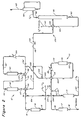
- Figure 1 is a schematic diagram of an isomerization process arranged in accordance with this invention showing indirect contact of the first effluent with the second feedstock and the recycle of hydrogen from the separation section.
- Figure 2 is schematic diagram of an isomerization zone arranged in accordance with this invention showing the direct mixing of the first effluent with the second feedstock and the mixing of a portion of the hydrogen stream with the second feedstock.
- This invention simplifies the simultaneous isomerization of C4 and C5-C6 feedstocks. It offers significant cost and operational advantages to newly designed units and is beneficial in the revamp of existing isomerization units to either add or improve butane isomerization capabilities.
- butane isomerization capability may be incorporated into an existing C5-C6 isomerization unit by adding as few pieces of major equipment as a butane drier, a feed exchanger, and one reactor.
- this invention can be incorporated into a new or existing isomerization unit in a variety of arrangements.
- Figure 1 provides a simplified flow diagram of one arrangement for the process of this invention.
- additional equipment such as valves, pumps and instruments have been omitted from Figure 1.
- the process of this invention uses a C4 isomerization zone 10, a C5-C6 isomerization zone 12, and a common separation facilities 14.
- This process uses two feedstreams, a first feedstock that enters an isomerization zone operated for C4 isomerization and a second feedstock that enters an isomerization zone operated for C5-C6 isomerization.
- the first feedstock and the second feedstock enter the process via lines 16 and 18, respectively, while a stream of make-up hydrogen enters the process through line 20. Both feedstocks and the make-up hydrogen pass respectively through a drier 17, 19 and 21 before entering the isomerization zones.
- the driers preferably contain an adsorbent material with a type 4A molecular sieve being particularly preferred for the hydrogen and C5-C6 feedstock and a type 13X molecular sieve being particularly preferred for the C4 feedstock.
- a type 4A molecular sieve being particularly preferred for the hydrogen and C5-C6 feedstock
- a type 13X molecular sieve being particularly preferred for the C4 feedstock.
- any type of drier that will meet the limitations for moisture as hereinafter discussed can be used for the feedstocks and hydrogen.
- the feedstock carried by line 16 is admixed with make-up hydrogen from line 20 to form a first combined feedstream.
- Line 22 carries the first combined feedstream through an exchanger 24 to heat the incoming feed against the effluent of the isomerization zone 10 carried by line 29.
- Final heating of the combined feedstream takes place in a charge heater 26 that exchanges the feedstream against medium pressure steam.
- the first combined feedstream enters a single reactor 28 that contains a hereinafter described preferred catalyst composition.
- the effluent from reactor 28 comprising a C4 isomerate product stream is taken from the reactor 28 by line 29, cooled in a charge beater 30 and exchanger 24 before entering separation section 14.
- line 18 carries the second feedstock into admixture with a stream of recycled hydrogen carried by line 32 to form a second combined feedstream transported by line 34.
- Line 34 conducts the second combined feedstream through a series of exchangers 36, 38 and charge heater 30.
- Isomerization zone 12 includes a first reactor 40 and a second reactor 42; both reactors 40 an 42 contain a preferred catalyst composition as hereinafter described. From charge heater 30, line 34 delivers the second combined feedstream to reactor 40.
- Reactor 40 contacts the feedstream with the catalyst contained therein to produce an intermediate isomerate product made up primarily of isopentanes and isohexanes.
- Line 44 conveys the isomerate product through exchanger 38 and into reactor 42.
- the C5-C6 isomerate product is withdrawn from reactor 42 by a line 46 which directs the C5-C6 isomerate product through exchanger 36 and into admixture with the C4 isomerate product carried by line 29 to produce a single isomerate product from the two feedstocks that first entered the process.
- the feedstocks that can be used in this invention include hydrocarbon fractions rich in C4 normal paraffins and hydrocarbon fractions rich in C5-C6 normal paraffins.
- the term "rich” is defined to mean a stream having more than 50% of the mentioned component.
- a suitable feedstream for the C4 isomerization zone will have at least 40 mol % normal butane with at least 25% of any balance comprising isobutane.
- Preferred feedstocks are substantially pure normal paraffin streams having over 60 mol% normal butane.
- Suitable C4 feedstreams are available from several sources in a refinery or as field butane streams.
- the feedstream for the C5-C6 isomerization zone will contain large quantities of normal and mono-methyl branched paraffins.
- Preferred feedstock are substantially pure normal hydrocarbons of roughly equal proportions of C5 and C6 paraffins.
- Other useful feedstocks include light natural gasoline, light straight run naphtha, gas oil condensate, light raffinates, light reformate, light hydrocarbons, and straight run distillates having distillation end points of about 77°C (170°F) and containing substantial quantities of C5 and C6 paraffins.
- the feedstream may also contain low concentrations of unsaturated hydrocarbons and hydrocarbons having more than 6 carbon atoms.
- the concentration of these materials should be limited to 10 wt.% for unsaturated compounds and 20 wt.% for heavier hydrocarbons in order to restrict hydrogen consumption and cracking reactions.
- the feed may also contain substantial quantities of naphthenic hydrocarbons, the concentration of these components should not normally exceed 35 mol%.
- Hydrogen is admixed with each feed in an amount that will provide a hydrogen to hydrocarbon ratio equal to or less than 1.0 at the inlet of the isomerization zone.
- the hydrogen to hydrocarbon ratio of 1 or less has been found to provide sufficient excess hydrogen for operation of the isomerization zones.
- the isomerization zones usually have a net consumption of hydrogen often referred to as the stoichiometric hydrogen requirement which is associated with a number of side reactions that occur. These side reactions include cracking and disproportionation. Other reactions that will also consume hydrogen include olefin and aromatics saturation.
- a preferred hydrogen to hydrocarbon ratio is between 0.05 to 0.5.
- Hydrogen may be added to the feed mixture in any manner that provides the necessary control for the addition of small hydrogen quantities. Metering and monitoring devices for this purpose are well known by those skilled in the art. As currently practiced, a control valve is used to meter the addition of hydrogen to the feed mixture. The hydrogen concentration in one or both of the effluent streams or one of the outlet stream fractions can be monitored by a hydrogen monitor and the control valve positions adjusted to maintain the desired hydrogen concentration.
- the hydrogen and hydrocarbon feed mixture entering either isomerization zone is contacted in at least one reaction zone with an isomerization catalyst
- a preferred isomerization catalyst consists of a high chloride catalyst on an alumina base containing platinum.
- the alumina is preferably an anhydrous gamma-alumina with a high degree of purity.
- the catalyst may also contain other platinum group metals.
- platinum group metals refers to noble metals excluding silver and gold which are selected from the group consisting of platinum, palladium, germanium, ruthenium, rhodium, osmium, and iridium.
- the catalyst will typically contain from about 0.1 to 0.25 wt.% of the platinum.
- Other platinum group metals may be present in a concentration of from 0.1 to 0.25 wt.%.
- the platinum component may exist within the final catalytic composite as an oxide or halide or as an elemental metal. The presence of the platinum component in its reduced state has been found most suitable for this process.
- the preferred catalyst also contains a chloride component.
- the chloride component termed in the art "a combined chloride” is present in an amount from about 2 to about 10 wt.% based upon the dry support material. The use of chloride in amounts greater than 4 wt.% have been found to be the most beneficial for this process.
- the method that has shown the best results in this invention prepares the catalyst by impregnating the carrier material through contact with an aqueous solution of a water-soluble decomposable compound of the platinum group metal.
- the impregnation is carried out by dipping the carrier material in a solution of chloroplatinic acid
- Additional solutions that may be used include ammonium chloroplatinate, bromoplatinic acid or platinum dichloride.
- Use of the platinum chloride compound serves the dual function of incorporating the platinum component and at least a minor quantity of the chloride into the catalyst.
- Additional amounts of the chloride must be incorporated into the catalyst by the addition or formation of aluminum chloride to or on the platinum-aluminum catalyst base.
- An alternate method of increasing the halogen concentration in the final catalyst composite is to use an aluminum hydrosol to form the aluminum carrier material such that the carrier material also contains at least a portion of the halogen.
- Halogen may also be added to the carrier material by contacting the calcined carrier material with an aqueous solution of the halogen acid such as hydrogen chloride, hydrogen fluoride, or hydrogen bromide.
- the feedstock and hydrogen stream may be treated by any method that will remove water and sulfur compounds. Sulfur may be removed from the feedstream by hydrotreating. A variety of commercial dryers are available to remove water from the feed components. Adsorption processes for the removal of sulfur and water from hydrocarbon streams are also well known to those skilled in the art.
- Operation of the isomerization zones with the preferred catalyst also requires the presence of a small amount of an organic chloride promoter.
- the organic chloride promoter serves to maintain a high level of active chloride on the catalyst as low levels are continuously stripped off the catalyst by the hydrocarbon feed.
- the concentration of promoter in the reaction zone is maintained at from 30 to 300 ppm.
- the preferred promoter compound is carbon tetrachloride.
- Other suitable promoter compounds include oxygen-free decomposable organic chlorides such as propyldichloride, butylchloride, methylenechloride, and chloroform to name only a few of such compounds.
- the need to keep the reactants dry is reinforced by the presence of the organic chloride compound which may convert, in part, to hydrogen chloride. As long as the process streams are kept dry, there will be no adverse effect from the presence of small amounts of hydrogen chloride.
- the core of the operation of the C4 isomerization zone is passage of the C4 feedstock through a reactor at butane isomerization-promoting conditions including the presence of an acidic isomerization catalyst.
- This is normally a relatively low pressure operation performed at a pressure of from about 700 to 4000 kPag and at an elevated temperature as required by the activity of the catalyst.
- the average reactant temperature may be as high as 500° C, but is preferably between 100 and 320° C.
- the C4 feedstock is passed vertically through one or more fixed beds of catalyst located within the reactor at a liquid hourly space velocity between 2.0 and 100 hr. ⁇ 1, but space velocities in the broad range of 0.5 to 12.0 hr. ⁇ 1 can be employed if desired.
- the C5-C6 isomerization zone will operate at conditions to maximize the isomerization of C5 and C6 hydrocarbons.
- temperatures within the reaction zone will range from about 90-225°C (194-435°F).
- Lower reaction temperatures in this range favor equilibrium mixtures of C5 and C6 isoalkanes versus normal pentane and hexane.
- higher temperatures in the range of 200-225°C (390-435°F) are preferred when large quantities of normal butanes are in the combined feed to the C5-C6 isomerization zone.
- the higher temperatures offer a significant increase in isobutane production with only a minimal decrease in the ratio of C5 and C6 isoalkanes to pentane and hexane.
- the most suitable temperature will depend on the composition of the feed. For feeds having few isomerizable C4 hydrocarbons, temperatures of between 120-205°C (248-400°F) may be most advantageous.
- the C5-C6 isomerization zone may also be maintained over a wide range of pressures. Pressure conditions in the isomerization of C5-C6 paraffins range from 700 to 7000 kPag. Preferred pressures for this isomerization are in the range of from 2000 to 3000 kPag.
- the feed rate to this reaction zone can also vary over a wide range and includes liquid hourly space velocities ranging from 0.5 to 10 hr. ⁇ 1, however, space velocities between 0.5 and 4 hr. ⁇ 1 are preferred.
- the C5-C6 isomerization zone will usually contain multiple stages.
- a typical C5-C6 isomerization zone will have a two-reactor system comprising a first stage reactor and a second stage reactor.
- the catalyst used in a multiple reaction stage system is usually distributed equally between the different reaction stages. It is not necessary that either reaction zone be carried out in two or more reactors but the use of at least two reactors confers several benefits on the process.
- the use of two reactors and specialized valving allows partial replacement of the catalyst in the system without taking the subject isomerization zone off stream. For the short periods of time during which replacement of catalyst may be necessary, the entire flow of reactants may be processed through only one reaction vessel while catalyst is replaced in the other.
- Two reactors can also be used to maintain lower catalyst temperatures in a portion of the C5-C6 isomerization zone. This is accomplished by having any exothermic reaction such as hydrogenation of unsaturates performed in a first reaction vessel with the rest of the reaction carried out in a final reactor stage at lower temperature conditions. Therefore, the first reactor can operate at a somewhat higher temperature, of about 200-225°C (390-435°F) which favors the isomerization of butanes and the lower temperature of the second reactor will increase the C5 and C6 isoparaffin to paraffins ratios by a small amount without reversing the isobutane yield. When two reactors are used in this manner, the last reactor in the C5-C6 isomerization zone can be operated at a temperature below 190°C (375°F) and possibly as low as 150°C (302°F).
- the process arrangement of this invention allows the process arrangement of this invention to take advantage of a beneficial heat integration.
- the second combined feed is first progressively heated by indirect heat exchange with the effluent from reactors 42 and 40.
- the C4 isomerate product carried by line 29 has enough heat, in most cases, to raise the temperature of the second combined feedstream to the desired inlet temperature for reactor 40.
- heat from line 29 may be supplemented, if necessary, by an additional charge heater if a higher inlet temperature is desired for reactor 40.
- heat from the C4 isomerate product may be transferred to the second combined feedstream by indirect heat exchange, direct contact, or a combination thereof.
- Figure 1 shows the isomerate products carried by lines 29 and 46 combined into a common product stream 48 that enters separation facilities for recovering the isomerization product.
- the separation facilities divide the reaction zone effluent into a product stream comprising C4 and heavier hydrocarbons and a gas stream which is made up of lighter hydrocarbons and hydrogen. Suitable designs for rectification columns and separator vessels are well known to those skilled in the art.
- the separation section may also include facilities for recovery of normal alkanes. Normal alkanes recovered from the separation facilities may be recycled to the isomerization reaction zone to increase the conversion of normal alkanes to isoalkanes.
- FIG. 1 One typical arrangement for the separation facilities is shown in Figure 1 and includes an overhead condensor 50 that cools the combined isomerate products and a product separator 52 that receives the cooled effluent from condensor 50 via line 48.
- Product separator 52 recovers hydrogen and other light gases in recycle stream 54 and directs unstabilized liquid products to a stabilizer column 56 by a line 58.
- Hydrogen from line 54 is compressed in a recycle compressor 55 for recycle to the C5-C6 isomerization zone by line 32.
- the stabilizer 56 column is operated to deliver a bottoms fraction 60 containing C4 and heavier hydrocarbons and an overhead fraction 62 of C3 hydrocarbons and lighter boiling compounds.
- Products taken from the bottom of the column can be cooled with the combined product stream in heat exchanger 64 before it enters the column.
- C3 and lighter hydrocarbons taken overhead from stabilizer column 56 can be cooled and separated into a gas stream and reflux that returns to the separation column.
- net gas from the separator column will ordinarily enter a scrubber section 66 that contacts the gas with a suitable treatment solution for neutralizing and/or removing acidic components that may have originated with the chloride addition to the isomerization zone and may be present in the gas stream.
- a suitable treatment solution for neutralizing and/or removing acidic components that may have originated with the chloride addition to the isomerization zone and may be present in the gas stream.
- the treatment solution will be a caustic that is pumped in a loop around a contacting vessel.
- the net gas is removed from the process by line 63 and usually put to use as a fuel.
- isomerate product from the C4 isomerization zone directly contacts the isomerate product from the C5-C6 isomerization zone and the separation facilities operate without the recycle of hydrogen.
- the process arrangement of Figure 2 still contains isomerization zones 10 and 12 and as described in conjunction with Figure 1 as well as separation facilities. This arrangement simplifies the process arrangement of Figure 1 by eliminating the product separator 52, the recycle compressor 55 and the heater 30 as shown in Figure 1.
- the C4 feedstock again enters the process via line 16 and after drying in drier 17 is combined with the dried hydrogen stream from line 20.
- the amount of hydrogen combined with the C4 feed may vary and at a minimum will equal the minimum amount of hydrogen necessary for the operation of the C4 isomerization zone and at a maximum will equal enough hydrogen to supply the hydrogen requirements of both isomerization zones.
- the first combined feedstream is taken by line 22 and passed through the first isomerization zone in the manner previously stated for the description of Figure 1.
- the effluent from reactor 28 is taken by line 100 and passed through exchanger 24 to heat the incoming feed.
- all or a portion of the isomerate product from the C4 isomerization zone is mixed directly with the second combined feedstream carried by line 34 to provide a mixed feedstream carried by line 34'. It is preferable to combine all of the isomerate product from line 100 directly with the second combined feedstream since this allows all of the required hydrogen for the C5-C6 isomerization zone to be transferred directly to the second feedstock and all of the available heat in line 100 to be utilized. Any flow capacity limitation will stem from space velocity limitations in the reactors of isomerization zone 12.
- the C5-C6 isomerization zone has insufficient flow capacity for all of the effluent carried by line 100, a portion of the line 100 effluent is diverted into the effluent from the C5-C6 isomerization zone by line 102. If the flow through line 102 is large, a heater similar to heater 30 shown in Figure 1 can be provided to heat the second feedstock against line 102. Thus in a further embodiment of this invention the effluent from the C4 isomerization can be split between line 100 and line 102, and the split regulated to control the space velocity in isomerization zone 12, the amount of hydrogen added to the second feedstock via line 100 and the amount of direct heating obtained from line 100.
- Figure 2 also shows the addition of a charge heater 106 for supplying additional heat to the mixed feedstream carried by line 34'.
- the use of the charge heater provides additional flexibility to the process by making up for any heat lost by the diversion of the C4 isomerate through line 102.
- the reactors and effluent heat exchange for isomerization zone 12 are essentially the same as that described in conjunction with Figure 1.
Description
- This invention relates generally to the isomerization of hydrocarbons. This invention relates more specifically to the isomerization of C₄, C₅ and C₆ cyclic hydrocarbons using a solid catalyst.
- High octane gasoline is required for modern gasoline engines. Formerly it was common to accomplish octane number improvement by the use of various lead-containing additives. As lead is phased out of gasoline for environmental reasons, it has become increasingly necessary to rearrange the structure of the hydrocarbons used in gasoline blending in order to achieve high octane ratings. Catalytic reforming and catalytic isomerization are two widely used processes for this upgrading.
- A gasoline blending pool normally included C₄ and heavier hydrocarbons having boiling points of less than 205°C (400°F) at atmospheric pressure. This range of hydrocarbon includes C₄-C₆ paraffins and especially the C₅ and C₆ normal paraffins which have relatively low octane numbers. The C₄-C₆ hydrocarbons have the greatest susceptibility to octane improvement by lead addition and were formerly upgraded in this manner. Octane improvement can also be obtained by using isomerization to rearrange the structure of the paraffinic hydrocarbons into branch-chained paraffins or reforming to convert the C₆ and heavier hydrocarbons to aromatic compounds. Normal C₅ hydrocarbons are not readily converted into aromatics, therefore, the common practice has been to isomerize these lighter hydrocarbons into corresponding branch-chained isoparaffins. Although the C₆ and heavier hydrocarbons can be upgraded into aromatics through hydrocyclization, the conversion of C₆'s to aromatics creates higher density species and increases gas yields with both effects leading to a reduction in liquid volume yields. Therefore, it is common practice to charge the C₆ paraffins to an isomerization unit to obtain C₆ isoparaffin hydrocarbons. Consequently, octane upgrading commonly uses isomerization to convert C₆ and lighter boiling hydrocarbons and reforming to convert C₇ and higher boiling hydrocarbons.
- The isomerization of paraffins is a reversible first order reaction. The reaction is limited by thermodynamic equilibrium. It has been generally found that lower temperatures shift the equilibrium of C₅ and C₆ hydrocarbons toward higher isoparaffin to normal paraffin ratios. These temperatures are typically in the range of 105-180°C (200-355°F). When isomerizing butane, its refractory nature demands somewhat higher temperatures usually greater than 170°C (340°F) to obtain high equilibrium ratios of isobutane to butane.
- A number of catalyst systems have been used in effecting isomerization reactions. Traditional catalyst systems are a hydrochloric acid promoted aluminum chloride system and a supported aluminum chloride catalyst. Recently zeolite catalysts, particularly mordenite, are also finding increased usage due to their decreased sensitivity to sulfur and water. A platinum group metal is usually incorporated into both catalysts. All of these catalyst systems are very reactive and can generate undesirable side reactions such as disproportionation and cracking. These side reactions not only decrease the product yield but can form olefinic fragments that combine with the catalyst and shorten its life. One commonly practiced method of controlling these undesired reactions has been to carry out the reaction in the presence of hydrogen. However, high concentrations of hydrogen and high molecular weight species tend to inhibit the butane isomerization reactions. Therefore, it has been difficult to isomerize butane in the presence of C₅-C₆ hydrocarbons without sacrificing isobutane yields or obtaining low yields of C₄-C₆ isoparaffins along with undesirable high gas production and catalyst fouling.
- As a result butane isomerization and the isomerization of C₅ and C₆ hydrocarbons are typically carried out in separate reaction zones and processes. The use of separate processes increases the equipment and operating expenses associated with the isomerizing of C₄ through C₆ hydrocarbons.
- U.S. Patent 3,242,228 issued to Riordan et al. teaches an isomerization catalyst consisting of an alumina base with 0.01 to 1.0 wt.% platinum, and 2.5 to 7.0 wt.% chlorine. The catalyst is used at process conditions including a liquid hourly space velocity (LHSV) of from 0.5 to 2.0 hr.⁻¹, a hydrogen to hydrocarbon mole ratio within the range of from 0.1:1 to 5.0:1, and a temperature of 150-200°C (300-390°F) for butane isomerization, or a temperature of 120-160°C (250-320°F) for C₅-C₆ isomerization.
- U.S. Patent 3,789,082 is directed to a method for practicing low temperature isomerization using a chlorided platinum-alumina catalyst. The process operates in the presence of a hydrogen chloride promoter in an amount up to 0.1 to 5 wt.% of the feedstock and temperatures in the range of 100-200°C (210-390°F) for the isomerization of feedstreams comprising C₄ and/or C₅ and/or C₆ fractions.
- U.S. Patent 4,113,789 mentions the isomerization of C₄-C₆ hydrocarbons at temperatures ranging from 120-180°C (250-355°F) and butane at temperatures ranging from 150-200°C (300-390°F) in the presence of a chlorided platinum alumina catalyst and hydrogen to hydrocarbon ratios in the range of 0.1:1.0 to 1:1.
- U. S. Patent 4,804,803 discloses a process for the isomerization of C₄-C₆ paraffins that uses a highly active chlorided, platinum alumina catalyst to carry out the process with a hydrogen to hydrocarbon ratio of 0.05 or less in the effluent from the isomerization zone.
- This invention is a process for the isomerization of a C₄ feedstock and a C₅-C₆ feedstock that reduces equipment and operating expenses by utilizing a process flow scheme that provides beneficial heat integration and facilitates the use of common recovery zone while permitting a wide variation in the relative ratio of the C₄ to the C₅-C₆ feedstock. The isomerization of the C₄ feedstock takes place in a separate reaction zone which is run at a higher temperature than the C₅ and C₆ hydrocarbon isomerization step. The effluent from the C₄ isomerization zone is heat exchanged against or mixed with the C₅-C₆ feedstock ahead of an additional isomerization zone that converts the C₅-C₆ hydrocarbons, and if present normal C₄ hydrocarbons, to more highly branched hydrocarbons. Effluents from both isomerization zones enter a common separation section that removes light gases from the isomerate product.
- Accordingly in one embodiment, this invention is a process for isomerizing a first feedstock comprising normal butane and a second feedstock comprising C₅ and C₆ paraffinic hydrocarbons. The process combines the first feedstock with a first hydrogen stream to produce a first combined feedstream comprising hydrogen and normal butane. The first combined feedstream is passed to a first isomerization zone and contacted, at butane isomerization conditions, including a higher temperature than that used in the second isomerization step, with an isomerization catalyst. A first isomerization zone effluent comprising isobutane and hydrogen is withdrawn from said first isomerization zone. The first isomerization zone effluent at least indirectly contacts the second feedstock thereby heating the second feedstock and a second hydrogen stream is admixed therewith to produce a second combined feedstream. The second combined feedstream passes to a second isomerization zone and contacts isomerization catalyst at conditions, including a temperature less than that utilized in the first step, for the isomerization of C₅ and C₆ hydrocarbons. A second isomerate effluent is withdrawn from the second isomerization zone and passed along with the first effluent to a common separation zone. A light gas stream containing hydrogen and at least one product stream comprising branched-chain hydrocarbons are withdrawn from said separation zone.
- In a more limited embodiment, this invention comprises a process for isomerizing a first feedstock comprising normal butane and a second feedstock comprising C₅ and C₆ paraffinic hydrocarbons. The process includes the steps of combining the first feedstock with a first hydrogen stream to produce a first combined feedstream comprising hydrogen and normal butane; passing the first combined feedstream to the first isomerization zone and contacting the first combined feedstream, at butane isomerization conditions, including a higher temperature than that utilized in the second isomerization zone, with an isomerization catalyst comprising alumina, 0.01 to 0.25 wt.% platinum and from 2-10 wt. % of a chloride component and withdrawing the first isomerization zone effluent comprising isobutane and hydrogen; mixing at least a portion of the first isomerization zone effluent with the second feedstock to heat same and to produce a second combined feedstream containing hydrogen and maintaining a hydrogen concentration in the second combined feedstream that will produce a hydrogen to hydrocarbon ratio in a second effluent stream from a second isomerization zone that is less than 0.1; passing the second combined feedstream to the second isomerization zone and contacting the second combined feedstream with an isomerization catalyst comprising alumina, 0.01 to 0.25 wt. % platinum and from 2-10 wt.% of a chloride component at conditions for the isomerization of C₅ and C₆ hydrocarbons, the conditions including a temperature that is lower than the temperature in the first isomerization zone, and withdrawing a second isomerization zone effluent having said hydrogen to hydrocarbon ratio of less than 0.1 from the second isomerization zone; passing the first and second effluent stream to a separation zone; withdrawing a first light gas stream, containing essentially all of the hydrogen entering the separation zone from the separation zone and removing the light gas stream from the process; and withdrawing at least one product stream comprising branched-chain hydrocarbons from the separation zone.
- Additional details, objects and embodiments of this invention are disclosed in the following detailed description of this invention.
- Figure 1 is a schematic diagram of an isomerization process arranged in accordance with this invention showing indirect contact of the first effluent with the second feedstock and the recycle of hydrogen from the separation section.
- Figure 2 is schematic diagram of an isomerization zone arranged in accordance with this invention showing the direct mixing of the first effluent with the second feedstock and the mixing of a portion of the hydrogen stream with the second feedstock.
- This invention simplifies the simultaneous isomerization of C₄ and C₅-C₆ feedstocks. It offers significant cost and operational advantages to newly designed units and is beneficial in the revamp of existing isomerization units to either add or improve butane isomerization capabilities. For example, butane isomerization capability may be incorporated into an existing C₅-C₆ isomerization unit by adding as few pieces of major equipment as a butane drier, a feed exchanger, and one reactor. Moreover, this invention can be incorporated into a new or existing isomerization unit in a variety of arrangements.
- Figure 1 provides a simplified flow diagram of one arrangement for the process of this invention. In order to facilitate an understanding of this invention, additional equipment such as valves, pumps and instruments have been omitted from Figure 1.
- As Figure 1 shows, the process of this invention uses a
C₄ isomerization zone 10, a C₅-C₆ isomerization zone 12, and acommon separation facilities 14. This process uses two feedstreams, a first feedstock that enters an isomerization zone operated for C₄ isomerization and a second feedstock that enters an isomerization zone operated for C₅-C₆ isomerization. The first feedstock and the second feedstock enter the process vialines line 20. Both feedstocks and the make-up hydrogen pass respectively through a drier 17, 19 and 21 before entering the isomerization zones. The driers preferably contain an adsorbent material with a type 4A molecular sieve being particularly preferred for the hydrogen and C₅-C₆ feedstock and a type 13X molecular sieve being particularly preferred for the C₄ feedstock. However, any type of drier that will meet the limitations for moisture as hereinafter discussed can be used for the feedstocks and hydrogen. - The feedstock carried by
line 16 is admixed with make-up hydrogen fromline 20 to form a first combined feedstream.Line 22 carries the first combined feedstream through anexchanger 24 to heat the incoming feed against the effluent of theisomerization zone 10 carried byline 29. Final heating of the combined feedstream takes place in acharge heater 26 that exchanges the feedstream against medium pressure steam. After final heating, the first combined feedstream enters asingle reactor 28 that contains a hereinafter described preferred catalyst composition. The effluent fromreactor 28 comprising a C₄ isomerate product stream is taken from thereactor 28 byline 29, cooled in acharge beater 30 andexchanger 24 before enteringseparation section 14. - Following passage through drier 19,
line 18 carries the second feedstock into admixture with a stream of recycled hydrogen carried byline 32 to form a second combined feedstream transported byline 34.Line 34 conducts the second combined feedstream through a series ofexchangers charge heater 30.Isomerization zone 12 includes afirst reactor 40 and asecond reactor 42; bothreactors 40 an 42 contain a preferred catalyst composition as hereinafter described. Fromcharge heater 30,line 34 delivers the second combined feedstream toreactor 40.Reactor 40 contacts the feedstream with the catalyst contained therein to produce an intermediate isomerate product made up primarily of isopentanes and isohexanes.Line 44 conveys the isomerate product throughexchanger 38 and intoreactor 42. Contact with the catalyst inreactor 42 further isomerizes the intermediate isomerate product stream to produce a C₅-C₆ isomerate product. The C₅-C₆ isomerate product is withdrawn fromreactor 42 by aline 46 which directs the C₅-C₆ isomerate product throughexchanger 36 and into admixture with the C₄ isomerate product carried byline 29 to produce a single isomerate product from the two feedstocks that first entered the process. - The feedstocks that can be used in this invention include hydrocarbon fractions rich in C₄ normal paraffins and hydrocarbon fractions rich in C₅-C₆ normal paraffins. The term "rich" is defined to mean a stream having more than 50% of the mentioned component. A suitable feedstream for the C₄ isomerization zone will have at least 40 mol % normal butane with at least 25% of any balance comprising isobutane. Preferred feedstocks are substantially pure normal paraffin streams having over 60 mol% normal butane. Suitable C₄ feedstreams are available from several sources in a refinery or as field butane streams.
- The feedstream for the C₅-C₆ isomerization zone will contain large quantities of normal and mono-methyl branched paraffins. Preferred feedstock are substantially pure normal hydrocarbons of roughly equal proportions of C₅ and C₆ paraffins. Other useful feedstocks include light natural gasoline, light straight run naphtha, gas oil condensate, light raffinates, light reformate, light hydrocarbons, and straight run distillates having distillation end points of about 77°C (170°F) and containing substantial quantities of C₅ and C₆ paraffins. The feedstream may also contain low concentrations of unsaturated hydrocarbons and hydrocarbons having more than 6 carbon atoms. The concentration of these materials should be limited to 10 wt.% for unsaturated compounds and 20 wt.% for heavier hydrocarbons in order to restrict hydrogen consumption and cracking reactions. The feed may also contain substantial quantities of naphthenic hydrocarbons, the concentration of these components should not normally exceed 35 mol%.
- Hydrogen is admixed with each feed in an amount that will provide a hydrogen to hydrocarbon ratio equal to or less than 1.0 at the inlet of the isomerization zone. The hydrogen to hydrocarbon ratio of 1 or less has been found to provide sufficient excess hydrogen for operation of the isomerization zones. Although no net hydrogen is consumed in the isomerization reactions, the isomerization zones usually have a net consumption of hydrogen often referred to as the stoichiometric hydrogen requirement which is associated with a number of side reactions that occur. These side reactions include cracking and disproportionation. Other reactions that will also consume hydrogen include olefin and aromatics saturation. High hydrogen concentrations tend to inhibit the isomerization of butanes by reducing the partial pressure of butane in the vapor phase and thus reducing the rate of reaction, therefore, high hydrogen to hydrocarbon ratios in the C₄ isomerization zone should be avoided. In general, a preferred hydrogen to hydrocarbon ratio is between 0.05 to 0.5.
- Hydrogen may be added to the feed mixture in any manner that provides the necessary control for the addition of small hydrogen quantities. Metering and monitoring devices for this purpose are well known by those skilled in the art. As currently practiced, a control valve is used to meter the addition of hydrogen to the feed mixture. The hydrogen concentration in one or both of the effluent streams or one of the outlet stream fractions can be monitored by a hydrogen monitor and the control valve positions adjusted to maintain the desired hydrogen concentration.
- The hydrogen and hydrocarbon feed mixture entering either isomerization zone is contacted in at least one reaction zone with an isomerization catalyst This invention can be practiced using a variety of different catalyst compositions and is not limited to a particular catalyst or combination of catalysts for either isomerization zone. A preferred isomerization catalyst consists of a high chloride catalyst on an alumina base containing platinum. In which case the alumina is preferably an anhydrous gamma-alumina with a high degree of purity. The catalyst may also contain other platinum group metals. The term platinum group metals refers to noble metals excluding silver and gold which are selected from the group consisting of platinum, palladium, germanium, ruthenium, rhodium, osmium, and iridium. These metals demonstrate differences in activity and selectivity such that platinum has now been found to be the most suitable for this process. The catalyst will typically contain from about 0.1 to 0.25 wt.% of the platinum. Other platinum group metals may be present in a concentration of from 0.1 to 0.25 wt.%. The platinum component may exist within the final catalytic composite as an oxide or halide or as an elemental metal. The presence of the platinum component in its reduced state has been found most suitable for this process.
- The preferred catalyst also contains a chloride component. The chloride component termed in the art "a combined chloride" is present in an amount from about 2 to about 10 wt.% based upon the dry support material. The use of chloride in amounts greater than 4 wt.% have been found to be the most beneficial for this process.
- There are a variety of ways for preparing the preferred catalytic composite and incorporating the platinum metal and the chloride therein. The method that has shown the best results in this invention prepares the catalyst by impregnating the carrier material through contact with an aqueous solution of a water-soluble decomposable compound of the platinum group metal. For best results, the impregnation is carried out by dipping the carrier material in a solution of chloroplatinic acid Additional solutions that may be used include ammonium chloroplatinate, bromoplatinic acid or platinum dichloride. Use of the platinum chloride compound serves the dual function of incorporating the platinum component and at least a minor quantity of the chloride into the catalyst. Additional amounts of the chloride must be incorporated into the catalyst by the addition or formation of aluminum chloride to or on the platinum-aluminum catalyst base. An alternate method of increasing the halogen concentration in the final catalyst composite is to use an aluminum hydrosol to form the aluminum carrier material such that the carrier material also contains at least a portion of the halogen. Halogen may also be added to the carrier material by contacting the calcined carrier material with an aqueous solution of the halogen acid such as hydrogen chloride, hydrogen fluoride, or hydrogen bromide.
- It is generally known that high chlorided platinum-alumina catalysts of this type are highly sensitive to sulfur and oxygen-containing compounds. Therefore, the feedstocks and any make-up hydrogen entering the process must be relatively free of such compounds when the preferred catalyst is used. A sulfur concentration no greater than 0.5 ppm is generally required. The presence of sulfur in the feedstock serves to temporarily deactivate the catalyst by platinum poisoning. Activity of the catalyst may be restored by hot hydrogen stripping of sulfur from the catalyst composite or by lowering the sulfur concentration in the incoming feed to below 0.5 ppm so that the hydrocarbon will desorb the sulfur that has been adsorbed on the catalyst. Water can act to permanently deactivate the catalyst by removing high activity chloride from the catalyst and replacing it with inactive aluminum hydroxide. Therefore, water, as well as oxygenates, in particular C₁-C₅ oxygenates, that can decompose to form water, can only be tolerated in very low concentrations. In general, this requires a limitation of oxygenates in the feed to about 0.1 ppm or less. The feedstock and hydrogen stream may be treated by any method that will remove water and sulfur compounds. Sulfur may be removed from the feedstream by hydrotreating. A variety of commercial dryers are available to remove water from the feed components. Adsorption processes for the removal of sulfur and water from hydrocarbon streams are also well known to those skilled in the art.
- Operation of the isomerization zones with the preferred catalyst also requires the presence of a small amount of an organic chloride promoter. The organic chloride promoter serves to maintain a high level of active chloride on the catalyst as low levels are continuously stripped off the catalyst by the hydrocarbon feed. The concentration of promoter in the reaction zone is maintained at from 30 to 300 ppm. The preferred promoter compound is carbon tetrachloride. Other suitable promoter compounds include oxygen-free decomposable organic chlorides such as propyldichloride, butylchloride, methylenechloride, and chloroform to name only a few of such compounds. The need to keep the reactants dry is reinforced by the presence of the organic chloride compound which may convert, in part, to hydrogen chloride. As long as the process streams are kept dry, there will be no adverse effect from the presence of small amounts of hydrogen chloride.
- Operating conditions within the isomerization zones are selected to provide a good selectivity of the particular isoalkane product from the feed components. The core of the operation of the C₄ isomerization zone is passage of the C₄ feedstock through a reactor at butane isomerization-promoting conditions including the presence of an acidic isomerization catalyst. This is normally a relatively low pressure operation performed at a pressure of from about 700 to 4000 kPag and at an elevated temperature as required by the activity of the catalyst. The average reactant temperature may be as high as 500° C, but is preferably between 100 and 320° C. It is preferred that the C₄ feedstock is passed vertically through one or more fixed beds of catalyst located within the reactor at a liquid hourly space velocity between 2.0 and 100 hr.⁻¹, but space velocities in the broad range of 0.5 to 12.0 hr.⁻¹ can be employed if desired.
- The C₅-C₆ isomerization zone will operate at conditions to maximize the isomerization of C₅ and C₆ hydrocarbons. Thus, temperatures within the reaction zone will range from about 90-225°C (194-435°F). Lower reaction temperatures in this range favor equilibrium mixtures of C₅ and C₆ isoalkanes versus normal pentane and hexane. However, higher temperatures in the range of 200-225°C (390-435°F) are preferred when large quantities of normal butanes are in the combined feed to the C₅-C₆ isomerization zone. The higher temperatures offer a significant increase in isobutane production with only a minimal decrease in the ratio of C₅ and C₆ isoalkanes to pentane and hexane. Of course, the most suitable temperature will depend on the composition of the feed. For feeds having few isomerizable C₄ hydrocarbons, temperatures of between 120-205°C (248-400°F) may be most advantageous. The C₅-C₆ isomerization zone may also be maintained over a wide range of pressures. Pressure conditions in the isomerization of C₅-C₆ paraffins range from 700 to 7000 kPag. Preferred pressures for this isomerization are in the range of from 2000 to 3000 kPag. The feed rate to this reaction zone can also vary over a wide range and includes liquid hourly space velocities ranging from 0.5 to 10 hr.⁻¹, however, space velocities between 0.5 and 4 hr.⁻¹ are preferred.
- The C₅-C₆ isomerization zone will usually contain multiple stages. A typical C₅-C₆ isomerization zone will have a two-reactor system comprising a first stage reactor and a second stage reactor. The catalyst used in a multiple reaction stage system is usually distributed equally between the different reaction stages. It is not necessary that either reaction zone be carried out in two or more reactors but the use of at least two reactors confers several benefits on the process. The use of two reactors and specialized valving (not shown) allows partial replacement of the catalyst in the system without taking the subject isomerization zone off stream. For the short periods of time during which replacement of catalyst may be necessary, the entire flow of reactants may be processed through only one reaction vessel while catalyst is replaced in the other. Two reactors can also be used to maintain lower catalyst temperatures in a portion of the C₅-C₆ isomerization zone. This is accomplished by having any exothermic reaction such as hydrogenation of unsaturates performed in a first reaction vessel with the rest of the reaction carried out in a final reactor stage at lower temperature conditions. Therefore, the first reactor can operate at a somewhat higher temperature, of about 200-225°C (390-435°F) which favors the isomerization of butanes and the lower temperature of the second reactor will increase the C₅ and C₆ isoparaffin to paraffins ratios by a small amount without reversing the isobutane yield. When two reactors are used in this manner, the last reactor in the C₅-C₆ isomerization zone can be operated at a temperature below 190°C (375°F) and possibly as low as 150°C (302°F).
- Operation of the C₄ isomerization zone at a relatively higher temperature than that of the C₅-C₆ isomerization zone and the operation of
reactor 40 at a relatively higher operating temperature thanreactor 42 allows the process arrangement of this invention to take advantage of a beneficial heat integration. As shown in Figure 1, the second combined feed is first progressively heated by indirect heat exchange with the effluent fromreactors line 29 has enough heat, in most cases, to raise the temperature of the second combined feedstream to the desired inlet temperature forreactor 40. Of course, heat fromline 29 may be supplemented, if necessary, by an additional charge heater if a higher inlet temperature is desired forreactor 40. As hereinafter described, heat from the C₄ isomerate product may be transferred to the second combined feedstream by indirect heat exchange, direct contact, or a combination thereof. - The effluents from both isomerization zones are combined following any heat exchange. Figure 1 shows the isomerate products carried by
lines common product stream 48 that enters separation facilities for recovering the isomerization product. At minimum, the separation facilities divide the reaction zone effluent into a product stream comprising C₄ and heavier hydrocarbons and a gas stream which is made up of lighter hydrocarbons and hydrogen. Suitable designs for rectification columns and separator vessels are well known to those skilled in the art. The separation section may also include facilities for recovery of normal alkanes. Normal alkanes recovered from the separation facilities may be recycled to the isomerization reaction zone to increase the conversion of normal alkanes to isoalkanes. One typical arrangement for the separation facilities is shown in Figure 1 and includes anoverhead condensor 50 that cools the combined isomerate products and aproduct separator 52 that receives the cooled effluent fromcondensor 50 vialine 48.Product separator 52 recovers hydrogen and other light gases inrecycle stream 54 and directs unstabilized liquid products to astabilizer column 56 by aline 58. Hydrogen fromline 54 is compressed in arecycle compressor 55 for recycle to the C₅-C₆ isomerization zone byline 32. Thestabilizer 56 column is operated to deliver abottoms fraction 60 containing C₄ and heavier hydrocarbons and anoverhead fraction 62 of C₃ hydrocarbons and lighter boiling compounds. Products taken from the bottom of the column can be cooled with the combined product stream inheat exchanger 64 before it enters the column. C₃ and lighter hydrocarbons taken overhead fromstabilizer column 56 can be cooled and separated into a gas stream and reflux that returns to the separation column. - When the preferred catalyst is used, net gas from the separator column will ordinarily enter a
scrubber section 66 that contacts the gas with a suitable treatment solution for neutralizing and/or removing acidic components that may have originated with the chloride addition to the isomerization zone and may be present in the gas stream. Typically, the treatment solution will be a caustic that is pumped in a loop around a contacting vessel. After treatment in the scrubber section, the net gas is removed from the process byline 63 and usually put to use as a fuel. - In most isomerization processes and as depicted by Figure 1, hydrogen is separated from the effluent in a product recovery section and recycled to the isomerization zone. When the hydrogen to hydrocarbon ratio of the reactor effluent is less than 0.05, it is possible to separate light ends from an isomerization effluent without the recovery and recycle of hydrogen to either of the isomerization zones. As the quantity of hydrogen leaving the product recovery section increases, additional amounts of C₄ and other product hydrocarbons are taken with the light ends that are separated from the process. These product hydrocarbons are typically in the fuel gas stream from the product recovery section. The value of the lost product or the additional expense associated with recovery facilities to prevent the loss of product do not normally justify operating the process without recycle at effluent hydrogen to hydrocarbon ratios above 0.05.
- In another embodiment of this process, as illustrated by Figure 2, isomerate product from the C₄ isomerization zone directly contacts the isomerate product from the C₅-C₆ isomerization zone and the separation facilities operate without the recycle of hydrogen. The process arrangement of Figure 2 still contains
isomerization zones product separator 52, therecycle compressor 55 and theheater 30 as shown in Figure 1. - Looking then at Figure 2, the C₄ feedstock again enters the process via
line 16 and after drying in drier 17 is combined with the dried hydrogen stream fromline 20. The amount of hydrogen combined with the C₄ feed may vary and at a minimum will equal the minimum amount of hydrogen necessary for the operation of the C₄ isomerization zone and at a maximum will equal enough hydrogen to supply the hydrogen requirements of both isomerization zones. The first combined feedstream is taken byline 22 and passed through the first isomerization zone in the manner previously stated for the description of Figure 1. The effluent fromreactor 28 is taken byline 100 and passed throughexchanger 24 to heat the incoming feed. - Depending on the flow capacity of the reactors in the C₅-C₆ isomerization zone, all or a portion of the isomerate product from the C₄ isomerization zone is mixed directly with the second combined feedstream carried by
line 34 to provide a mixed feedstream carried by line 34'. It is preferable to combine all of the isomerate product fromline 100 directly with the second combined feedstream since this allows all of the required hydrogen for the C₅-C₆ isomerization zone to be transferred directly to the second feedstock and all of the available heat inline 100 to be utilized. Any flow capacity limitation will stem from space velocity limitations in the reactors ofisomerization zone 12. If the C₅-C₆ isomerization zone has insufficient flow capacity for all of the effluent carried byline 100, a portion of theline 100 effluent is diverted into the effluent from the C₅-C₆ isomerization zone by line 102. If the flow through line 102 is large, a heater similar toheater 30 shown in Figure 1 can be provided to heat the second feedstock against line 102. Thus in a further embodiment of this invention the effluent from the C₄ isomerization can be split betweenline 100 and line 102, and the split regulated to control the space velocity inisomerization zone 12, the amount of hydrogen added to the second feedstock vialine 100 and the amount of direct heating obtained fromline 100. - When all of the hydrogen requirements for
isomerization zone 12 cannot be supplied by the effluent fromisomerization zone 10, a portion of the hydrogen for the C₅-C₆ isomerization zone is supplied by diverting a portion of hydrogen stream fromline 20 intoline 104. Even when all of the effluent fromisomerization zone 10 is combined with the C₅-C₆ feedstock, it may still be desirable to supply a portion of the hydrogen requirements forisomerization zone 12 throughline 104 in order to lower the hydrogen partial pressure inisomerization zone 10. - Figure 2 also shows the addition of a
charge heater 106 for supplying additional heat to the mixed feedstream carried by line 34'. The use of the charge heater provides additional flexibility to the process by making up for any heat lost by the diversion of the C₄ isomerate through line 102. Except as otherwise described, the reactors and effluent heat exchange forisomerization zone 12 are essentially the same as that described in conjunction with Figure 1. - All of the effluent from both isomerization zones is eventually combined and together enters a
separation facility 108 vialine 110. The combined effluent is carried byline 110 through acondensor 112 and directly into a stabilizer column. Since in this embodiment both isomerization zones operate with a minimum hydrogen to hydrocarbon ratio, there is no need for a product separator to recover hydrogen for recycle to the isomerization zones. Apart from a slightly higher hydrogen concentration in the stabilizer overhead stream, the operation of the stabilizer section for the embodiment of Figure 2 parallel that of Figure 1.
Claims (6)
- A process for isomerizing a first feedstock comprising normal butane and a second feedstock comprising C₅ and C₆ acyclic hydrocarbons, said process comprising;a) combining said first feedstock with a first hydrogen stream to produce a first combined feedstream comprising hydrogen and normal butane;b) passing said first combined feedstream to a first isomerization zone and contacting said first combined feedstream, at butane isomerization conditions, including a temperature greater than that utilized in step (a), with an isomerization catalyst and withdrawing a first effluent stream comprising isobutane and hydrogen;c) heating said second feedstock by at least indirectly contacting said first isomerization zone effluent with said second feedstock and admixing a second hydrogen stream with said second feedstock to produce a second combined feedstream;d) passing said second combined feedstream to a second isomerization zone and contacting said second combined feedstream with an isomerization catalyst at conditions, including a temperature less than that utilized in step (b), for the isomerization of C₅ and C₆ hydrocarbons and withdrawing a second effluent stream comprising isomerized C₅ and C₆ hydrocarbons;e) passing said first and second effluent streams to a common separation zone;f) withdrawing a first light gas stream comprising hydrogen from said separation zone; andg) withdrawing at least one product stream comprising branched-chain hydrocarbons from said separation zone.
- The process of Claim 1 wherein said second hydrogen stream is obtained by recycling at least a portion of said first light gas stream.
- The process of Claim 1 or 2 wherein at least a portion of said first effluent stream is mixed with said second feedstock to effect said heating step (c) and to supply, at least in part, said second hydrogen stream.
- The process of Claim 1, 2 or 3 wherein the isomerization conditions in said first isomerization zone include LHSV in a range of from 2 to 10 hr.⁻¹, a temperature in a range of from 100 to 300°C and a pressure in a range of from 700 to 4000 kpag, and the isomerization conditions in said second isomerization zone include an LHSV in a range of from 0.5 to 4 hr.⁻¹, a temperature in a range of from 90°C to 225°C, and a pressure in a range of from 2000 to 3000kPag.
- The process of any one of Claims 1 to 4 wherein said first feedstock is admixed with hydrogen in an amount that will produce a hydrogen to hydrocarbon ratio of less than 0.5 in said first effluent stream and said second feedstock is admixed with hydrogen in an amount that will produce a hydrogen to hydrocarbon ratio of less than 0.05 in said second effluent stream.
- The process of any one of Claims 1 to 5 wherein the isomerization catalyst in said first and second isomerization zones comprises alumina, 0.01 to 0.25 wt.% platinum and from 2 to 10 wt.% of a chloride component.
Priority Applications (4)
| Application Number | Priority Date | Filing Date | Title |
|---|---|---|---|
| US07/459,160 US5082989A (en) | 1989-12-29 | 1989-12-29 | Integrated process for C4, C5 and C6 isomerization |
| DE69107448T DE69107448T2 (en) | 1989-12-29 | 1991-06-24 | Integrated process with two reaction zones for the isomerization of C4, C5 and C6 hydrocarbons. |
| EP91305685A EP0520100B1 (en) | 1989-12-29 | 1991-06-24 | Integrated two reaction zone process for C4, C5 and C6 isomerization |
| ES91305685T ES2067867T3 (en) | 1989-12-29 | 1991-06-24 | INTEGRATED PROCEDURE IN TWO REACTION AREAS FOR C4, C5 AND C6 HYDROCARBON ISOMERIZATION. |
Applications Claiming Priority (2)
| Application Number | Priority Date | Filing Date | Title |
|---|---|---|---|
| US07/459,160 US5082989A (en) | 1989-12-29 | 1989-12-29 | Integrated process for C4, C5 and C6 isomerization |
| EP91305685A EP0520100B1 (en) | 1989-12-29 | 1991-06-24 | Integrated two reaction zone process for C4, C5 and C6 isomerization |
Publications (2)
| Publication Number | Publication Date |
|---|---|
| EP0520100A1 EP0520100A1 (en) | 1992-12-30 |
| EP0520100B1 true EP0520100B1 (en) | 1995-02-15 |
Family
ID=40275962
Family Applications (1)
| Application Number | Title | Priority Date | Filing Date |
|---|---|---|---|
| EP91305685A Expired - Lifetime EP0520100B1 (en) | 1989-12-29 | 1991-06-24 | Integrated two reaction zone process for C4, C5 and C6 isomerization |
Country Status (4)
| Country | Link |
|---|---|
| US (1) | US5082989A (en) |
| EP (1) | EP0520100B1 (en) |
| DE (1) | DE69107448T2 (en) |
| ES (1) | ES2067867T3 (en) |
Families Citing this family (13)
| Publication number | Priority date | Publication date | Assignee | Title |
|---|---|---|---|---|
| US5453552A (en) * | 1993-08-20 | 1995-09-26 | Uop | Isomerization and adsorption process with benzene saturation |
| US6204426B1 (en) * | 1999-12-29 | 2001-03-20 | Chevron U.S.A. Inc. | Process for producing a highly paraffinic diesel fuel having a high iso-paraffin to normal paraffin mole ratio |
| US8157893B2 (en) * | 2009-06-16 | 2012-04-17 | Uop Llc | Apparatus and process for isomerizing a hydrocarbon stream |
| US8163068B2 (en) * | 2009-06-16 | 2012-04-24 | Uop Llc | Apparatus and process for isomerizing a hydrocarbon stream |
| US8163067B2 (en) * | 2009-06-16 | 2012-04-24 | Uop Llc | Apparatus and process for isomerizing a hydrogen stream |
| US8062613B2 (en) * | 2009-09-16 | 2011-11-22 | Uop Llc | Apparatus and process for isomerizing a hydrocarbon stream |
| US8685175B2 (en) * | 2009-09-16 | 2014-04-01 | Uop Llc | Apparatus and process for isomerizing a hydrocarbon stream |
| US9567271B2 (en) | 2014-09-03 | 2017-02-14 | Uop Llc | Process for the recovery of paraffins from an isomerization effluent |
| US9683181B2 (en) | 2014-09-05 | 2017-06-20 | Uop Llc | Process for controlling the temperature of a feed stream to an isomerization zone |
| US20190003343A1 (en) * | 2017-06-30 | 2019-01-03 | Uop Llc | Process and apparatus for using a waste heat stream in an aromatics complex |
| CN111278793A (en) * | 2017-08-28 | 2020-06-12 | 沙特基础工业全球技术公司 | System and method for converting n-butane to isobutane |
| US10414990B1 (en) * | 2018-05-03 | 2019-09-17 | Uop Llc | Processes for isomerizing hydrocarbons |
| US11708311B2 (en) * | 2021-12-10 | 2023-07-25 | Uop Llc | Process for isomerizing isobutane |
Family Cites Families (8)
| Publication number | Priority date | Publication date | Assignee | Title |
|---|---|---|---|---|
| US2908735A (en) * | 1956-01-11 | 1959-10-13 | Universal Oil Prod Co | Isomerization of normal butane |
| US2939896A (en) * | 1957-12-09 | 1960-06-07 | Phillips Petroleum Co | Isomerization process and catalyst |
| US3112351A (en) * | 1959-07-20 | 1963-11-26 | Universal Oil Prod Co | Isomerization of hydrocarbons |
| US3242228A (en) * | 1962-12-07 | 1966-03-22 | Texaco Inc | Hydrocarbon isomerization process and catalyst |
| CA928728A (en) * | 1971-01-26 | 1973-06-19 | J. Cook Terence | Isomerisation of paraffin hydrocarbons |
| US4113789A (en) * | 1977-03-03 | 1978-09-12 | Texaco Inc. | Hydroisomerization of normal paraffin with a catalyst of noble metal, alumina support and chlorine |
| US4804803A (en) * | 1987-12-07 | 1989-02-14 | Uop Inc. | Isomerization with once-through hydrogen |
| US4877919A (en) * | 1988-04-25 | 1989-10-31 | Uop | Butane isomerization in the presence of C5 and C6 hydrocarbons |
-
1989
- 1989-12-29 US US07/459,160 patent/US5082989A/en not_active Expired - Fee Related
-
1991
- 1991-06-24 EP EP91305685A patent/EP0520100B1/en not_active Expired - Lifetime
- 1991-06-24 DE DE69107448T patent/DE69107448T2/en not_active Expired - Fee Related
- 1991-06-24 ES ES91305685T patent/ES2067867T3/en not_active Expired - Lifetime
Also Published As
| Publication number | Publication date |
|---|---|
| ES2067867T3 (en) | 1995-04-01 |
| US5082989A (en) | 1992-01-21 |
| EP0520100A1 (en) | 1992-12-30 |
| DE69107448D1 (en) | 1995-03-23 |
| DE69107448T2 (en) | 1995-06-22 |
Similar Documents
| Publication | Publication Date | Title |
|---|---|---|
| US4804803A (en) | Isomerization with once-through hydrogen | |
| US4783575A (en) | Isomerization with cyclic hydrocarbon conversion | |
| US7223898B2 (en) | Isomerization process | |
| CA2038824C (en) | Combination process for hydrogenation and isomerization of benzene- and paraffin-containing feedstocks | |
| US5360534A (en) | Isomerization of split-feed benzene-containing paraffinic feedstocks | |
| US4834866A (en) | Process for converting normal and cyclic paraffins | |
| EP1992673A1 (en) | Isomerization of benzene-containing feedstocks | |
| EP0520100B1 (en) | Integrated two reaction zone process for C4, C5 and C6 isomerization | |
| EP0519131B1 (en) | Process for paraffin isomerization with liquid phase adsorptive product separation and with direct recycle of extract stream | |
| US7638665B2 (en) | Isomerization of benzene-containing feedstocks | |
| US5227554A (en) | Isomerization process | |
| US5026950A (en) | Hydrotreatment-isomerization without hydrogen recycle | |
| US5326926A (en) | Isomerization with improved RVP and C4 recovery | |
| US4929794A (en) | Hydrotreatment-isomerization without hydrogen recycle | |
| US4877919A (en) | Butane isomerization in the presence of C5 and C6 hydrocarbons | |
| US5763713A (en) | Process for the isomerization of benzene containing feed streams | |
| CA2045356C (en) | Integrated two reaction zone process for c4, c5 and c6 isomerization | |
| AU638139B2 (en) | Integrated two reaction zone process for c4, c5 and c6 isomerization | |
| US20080286172A1 (en) | Isomerization of Benzene-Containing Feedstocks | |
| Johnson et al. | Integrated process for C 4, C 5 and C 6 isomerization | |
| US5962755A (en) | Process for the isomerization of benzene containing feed streams | |
| KR910009001B1 (en) | Process for isomerization of c4 to c6 hydrocarbons with once - through hydrocarbons | |
| CA1312884C (en) | Process for isomerization of c_ to c_ hydrocarbons with once-through hydrogen | |
| GB1604900A (en) | Preparation of a pentane/hexane feedstock for isomerisation and the isomerisation process including such preparation | |
| NO176241B (en) | Process for isomerization of C4-C6 hydrocarbons |
Legal Events
| Date | Code | Title | Description |
|---|---|---|---|
| PUAI | Public reference made under article 153(3) epc to a published international application that has entered the european phase |
Free format text: ORIGINAL CODE: 0009012 |
|
| AK | Designated contracting states |
Kind code of ref document: A1 Designated state(s): BE DE ES FR GB IT NL SE |
|
| 17P | Request for examination filed |
Effective date: 19930604 |
|
| 17Q | First examination report despatched |
Effective date: 19940520 |
|
| GRAA | (expected) grant |
Free format text: ORIGINAL CODE: 0009210 |
|
| AK | Designated contracting states |
Kind code of ref document: B1 Designated state(s): BE DE ES FR GB IT NL SE |
|
| REF | Corresponds to: |
Ref document number: 69107448 Country of ref document: DE Date of ref document: 19950323 |
|
| ET | Fr: translation filed | ||
| REG | Reference to a national code |
Ref country code: ES Ref legal event code: FG2A Ref document number: 2067867 Country of ref document: ES Kind code of ref document: T3 |
|
| ITF | It: translation for a ep patent filed |
Owner name: MODIANO & ASSOCIATI S.R.L. |
|
| PLBE | No opposition filed within time limit |
Free format text: ORIGINAL CODE: 0009261 |
|
| STAA | Information on the status of an ep patent application or granted ep patent |
Free format text: STATUS: NO OPPOSITION FILED WITHIN TIME LIMIT |
|
| 26N | No opposition filed | ||
| REG | Reference to a national code |
Ref country code: GB Ref legal event code: IF02 |
|
| PGFP | Annual fee paid to national office [announced via postgrant information from national office to epo] |
Ref country code: DE Payment date: 20030630 Year of fee payment: 13 |
|
| PGFP | Annual fee paid to national office [announced via postgrant information from national office to epo] |
Ref country code: NL Payment date: 20040528 Year of fee payment: 14 |
|
| PGFP | Annual fee paid to national office [announced via postgrant information from national office to epo] |
Ref country code: SE Payment date: 20040621 Year of fee payment: 14 |
|
| PG25 | Lapsed in a contracting state [announced via postgrant information from national office to epo] |
Ref country code: DE Free format text: LAPSE BECAUSE OF NON-PAYMENT OF DUE FEES Effective date: 20050101 |
|
| PGFP | Annual fee paid to national office [announced via postgrant information from national office to epo] |
Ref country code: FR Payment date: 20050617 Year of fee payment: 15 |
|
| PG25 | Lapsed in a contracting state [announced via postgrant information from national office to epo] |
Ref country code: IT Free format text: LAPSE BECAUSE OF NON-PAYMENT OF DUE FEES;WARNING: LAPSES OF ITALIAN PATENTS WITH EFFECTIVE DATE BEFORE 2007 MAY HAVE OCCURRED AT ANY TIME BEFORE 2007. THE CORRECT EFFECTIVE DATE MAY BE DIFFERENT FROM THE ONE RECORDED. Effective date: 20050624 |
|
| PG25 | Lapsed in a contracting state [announced via postgrant information from national office to epo] |
Ref country code: SE Free format text: LAPSE BECAUSE OF NON-PAYMENT OF DUE FEES Effective date: 20050625 |
|
| PG25 | Lapsed in a contracting state [announced via postgrant information from national office to epo] |
Ref country code: NL Free format text: LAPSE BECAUSE OF NON-PAYMENT OF DUE FEES Effective date: 20060101 |
|
| EUG | Se: european patent has lapsed | ||
| NLV4 | Nl: lapsed or anulled due to non-payment of the annual fee |
Effective date: 20060101 |
|
| REG | Reference to a national code |
Ref country code: FR Ref legal event code: ST Effective date: 20070228 |
|
| PG25 | Lapsed in a contracting state [announced via postgrant information from national office to epo] |
Ref country code: FR Free format text: LAPSE BECAUSE OF NON-PAYMENT OF DUE FEES Effective date: 20060630 |
|
| PGFP | Annual fee paid to national office [announced via postgrant information from national office to epo] |
Ref country code: ES Payment date: 20080616 Year of fee payment: 18 |
|
| PGFP | Annual fee paid to national office [announced via postgrant information from national office to epo] |
Ref country code: BE Payment date: 20080630 Year of fee payment: 18 |
|
| PGFP | Annual fee paid to national office [announced via postgrant information from national office to epo] |
Ref country code: GB Payment date: 20080506 Year of fee payment: 18 |
|
| BERE | Be: lapsed |
Owner name: *UOP Effective date: 20090630 |
|
| GBPC | Gb: european patent ceased through non-payment of renewal fee |
Effective date: 20090624 |
|
| PG25 | Lapsed in a contracting state [announced via postgrant information from national office to epo] |
Ref country code: GB Free format text: LAPSE BECAUSE OF NON-PAYMENT OF DUE FEES Effective date: 20090624 |
|
| PG25 | Lapsed in a contracting state [announced via postgrant information from national office to epo] |
Ref country code: BE Free format text: LAPSE BECAUSE OF NON-PAYMENT OF DUE FEES Effective date: 20090630 |
|
| REG | Reference to a national code |
Ref country code: ES Ref legal event code: FD2A Effective date: 20090625 |
|
| PG25 | Lapsed in a contracting state [announced via postgrant information from national office to epo] |
Ref country code: ES Free format text: LAPSE BECAUSE OF NON-PAYMENT OF DUE FEES Effective date: 20090625 |