EP0520063B1 - Tambourine - Google Patents
Tambourine Download PDFInfo
- Publication number
- EP0520063B1 EP0520063B1 EP92903852A EP92903852A EP0520063B1 EP 0520063 B1 EP0520063 B1 EP 0520063B1 EP 92903852 A EP92903852 A EP 92903852A EP 92903852 A EP92903852 A EP 92903852A EP 0520063 B1 EP0520063 B1 EP 0520063B1
- Authority
- EP
- European Patent Office
- Prior art keywords
- frame
- grooves
- musical instrument
- specified
- slots
- Prior art date
- Legal status (The legal status is an assumption and is not a legal conclusion. Google has not performed a legal analysis and makes no representation as to the accuracy of the status listed.)
- Expired - Lifetime
Links
Images


Classifications
-
- G—PHYSICS
- G10—MUSICAL INSTRUMENTS; ACOUSTICS
- G10D—STRINGED MUSICAL INSTRUMENTS; WIND MUSICAL INSTRUMENTS; ACCORDIONS OR CONCERTINAS; PERCUSSION MUSICAL INSTRUMENTS; AEOLIAN HARPS; SINGING-FLAME MUSICAL INSTRUMENTS; MUSICAL INSTRUMENTS NOT OTHERWISE PROVIDED FOR
- G10D13/00—Percussion musical instruments; Details or accessories therefor
- G10D13/01—General design of percussion musical instruments
- G10D13/06—Castanets, cymbals, triangles, tambourines without drumheads or other single-toned percussion musical instruments
-
- G—PHYSICS
- G10—MUSICAL INSTRUMENTS; ACOUSTICS
- G10D—STRINGED MUSICAL INSTRUMENTS; WIND MUSICAL INSTRUMENTS; ACCORDIONS OR CONCERTINAS; PERCUSSION MUSICAL INSTRUMENTS; AEOLIAN HARPS; SINGING-FLAME MUSICAL INSTRUMENTS; MUSICAL INSTRUMENTS NOT OTHERWISE PROVIDED FOR
- G10D13/00—Percussion musical instruments; Details or accessories therefor
- G10D13/10—Details of, or accessories for, percussion musical instruments
Definitions
- the invention is concerned with a musical instrument having a curved frame and jingles mounted on said frame.
- U.S. Patent 4 230 015 describes a tambourine which includes an arcuate frame having a plurality of jingle members affixed to the frame.
- the frame is formed with two arcs like a half-moon, and near the center of gravity of the frame a grasping portion is disposed such that the tambourine may be comfortably held.
- GB 1 142 365 describes a tambourine in which the support for the skin comprises a body member made of a molded plastic material.
- the jingles or cymbals thereof are mounted on support pins which are located in holes in the side walls of slots provided in the moled body member.
- the object of the present invention is to provide for an improved mounting arrangement of the jingles or cymbals in the frame so as to avoid loosening or falling out of the jingle pins, nails, or screws during vigorous play of such kind of instrument.
- a tambourine having jingle members mounted on a plastic frame.
- the frame is formed as an elongated web having two transverse hinges formed thereon which divide the frame longitudinally into a central frame section and two end frame sections.
- the frame is folded at the hinges and curved longitudinally with the frame ends being joined to a connecting member such that the frame is shaped into the form of intersecting arcs, one formed by the central frame section and the other formed by the connecting member and the end frame sections.
- the hinges can be formed as transverse grooves on the web which divide the frame sections and may be provided with ridges on the surface of the web opposite the grooves to maintain material thickness for ease in molding.
- the connecting member is a contoured handle for holding the tambourine.
- the connecting member is a mounting bracket for mounting the tambourine, for example, to a drum stand.
- the transverse edge of the tambourine may be provided with a curved contour with an enlarged radius of curvature compared to the thickness of the frame to provide reinforcement to the frame, a larger surface to ease the impact on the player's hand and a larger surface for striking the tambourine with a drumstick.
- a cushioned edge strip may be provided.
- the jingles of a tambourine or other percussion musical instrument are mounted to a supporting frame having transversely adjacent slots. At least two grooves are provided on one side of the frame extending in a transverse direction and each intersecting one of the slots. At least one groove is provided on the other side of the frame which extends between and intersects two slots.
- the grooves are axially aligned and have depths selected to accommodate a pin passing through the grooves on both sides of the frame and the grooves have closed ends for retaining the ends of a pin with jingles mounted thereon.
- Figure 1 is a top view of one embodiment of a tambourine according to the present invention.
- Figure 2 is a rear view of the Figure 1 tambourine.
- Figure 3 is a plan view of the frame member for the Figure 1 tambourine.
- Figure 4 is a detailed cross-sectional view of the Figure 3 frame.
- Figure 5 is a detailed cross-sectional view of the Figure 3 frame.
- Figure 6 is a detailed cross-sectional view of the Figure 3 frame.
- Figure 7 is a detailed cross-sectional view of the Figure 3 frame.
- Figure 8 is a detailed cross-sectional view of the Figure 3 frame.
- Figure 9 is a cross-sectional drawing of an alternate arrangement for the Figure 3 frame.
- Figure 10 is a cross-sectional drawing of a cushioning strip for use with the frame arrangement shown in Figure 9.
- Figure 11 is a simplified cross-sectional drawing of a frame illustrating the mounting of jingle members thereon.
- Figure 12 is a simplified cross-sectional drawing of a frame showing jingle members in their mounted position.
- Figure 13 is a top view, partially sectioned, illustrating an alternate connecting member in accordance with the invention.
- Figure 14 is a rear view, partially sectioned, showing the arrangement of the alternate embodiment of Figure 13.
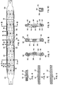
- a tambourine 10 according to the present invention is shown in a top view in Figure 1 and a rear view in Figure 2.
- Tambourine 10 includes a frame member 12 which is fabricated in a single piece of suitable plastic material, such as nylon type 6/6 with Shore hardness D 65-70.
- Frame 12 is shown in plane view in Figure 3 and consists of an elongated web of molded plastic having hinges 18 which divide the frame member into a central section 22 and end sections 20 and 24.
- the assembled tambourine shown in Figure 1 further includes a connecting member 14 which has flanges 28 and 30 jointed to the end sections 24 and 20 of frame 12. Central section 26 of connecting member 14 joins flanges 28 and 30 with a mounting member 32. Flanges 28 and 30 are angled with respect to each other and central section 26 so that end sections 20 and 24 are maintained in an approximately circular arc. Likewise, central section 22 is bent into an approximately circular arc when the tambourine 10 is assembled. The assembled tambourine 10 and assumes the shape of two intersecting arcs.
- Jingle members 16 are mounted in twelve or fourteen 12 jingle slots 34 as will be further described.
- FIG. 3 through 8 Details of the construction of frame member 12 are shown in Figures 3 through 8.
- the arrangement of hinges 18 is shown in the cross-sectional view of Figure 4 which shows the hinges formed by a groove 35 in one side of frame 12 and a ridge 37 on the opposite side. Ridge 37 provides mechanical strength and maintains a uniform part thickness, which is desirable for the molding process.
- Figures 5 and 6 show the arrangement of grooves for holding the jingle mounting pins 44.
- Grooves 36 are formed on the transversely outer sides of slots 34 extending transversely and each intersecting one of slots 34.
- a central groove 38 is formed on the opposite side of frame 12 in axially alignment with grooves 36 in the space between transversely adjacent jingle slots 34.
- Groove 38 extends between and intersects the two adjacent slots. As shown in detail in Figure 7 grooves 36 have closed ends for retaining the ends of jingle pin 44. The depths 48, 50 of grooves 36 and 38 respectively are selected so that the pin 44 can pass in a straight line between grooves 36 and 38 providing a three point support for the jingle pin 44.
- the outer surface of frame 12 include ridges 40 and 42 on the opposite side of grooves 38 and 36 respectively for reinforcing the frame against bending or breakage in the region of the grooves and maintaining uniform thickness for the frame molding process. Ridges 40 and 42 have an outward extension 52 corresponding to the depths 48, 50 of the grooves.
- the transverse edges of frame 12 are provided with a rounded configuration 46 having a radius which is greater than one-half the thickness of the frame.
- This rounded and reinforced edge is more comfortable to the hand of a player when the tambourine is struck against the hand in a common playing technique.
- this edge is particularly suitable for striking with a drumstick.
- grooves 54 extend longitudinally along the transverse edge of frame 12 for receiving a cushion strip 56 shown in Figure 10.
- Strip 56 has a C-shaped cross-section so that the edges 60 of the C-shaped portion can be received in grooves 54.
- Strip 56 can be provided in material having varied durometer to suit the player of the instrument. A suitable range of durometer would be Shore A scale about 35 to 70.
- strip 56 can be molded onto frame 12 in a second co-molding process.
- Figures 11 and 12 illustrate how jingles 16 can be mounted in frame 12 using a spring pin 44.
- Pin 44 is inserted over groove 36 through a first set of jingles 16, through groove 38 then through a further set of jingles and into the opposite groove 36. During the insertion process, spring pin 44 is bent and then returns to the straight configuration shown in Figure 12.
- Figures 13 and 14 show an alternate configuration wherein the connecting member comprises a contoured handle having a first handle member 64 which is connected to one side of end sections 20 and 24.
- a second handle portion 66 is placed over the other side of end sections 20 and 24 and attached to member 64, for example, by adhesive.
- Handle portion 66 can also be provided with a recess for accommodating a softer cushion pad on the inner side of the handle for comfort.
- the tambourine according to the present invention provides a strong and durable construction with easy fabrication out of a single piece frame member.
- the jingle mounting configuration provides substantial restraints against jingle pin detachment and consequent loss of jingle.
- the overall non-circular shape of the tambourine provides an easier and more comfortable distribution of the tambourine weight for extended and vigorous playing.
Landscapes
- Physics & Mathematics (AREA)
- Engineering & Computer Science (AREA)
- Acoustics & Sound (AREA)
- Multimedia (AREA)
- Mirrors, Picture Frames, Photograph Stands, And Related Fastening Devices (AREA)
- Mutual Connection Of Rods And Tubes (AREA)
- Transition And Organic Metals Composition Catalysts For Addition Polymerization (AREA)
- Organic Low-Molecular-Weight Compounds And Preparation Thereof (AREA)
- Nitrogen And Oxygen Or Sulfur-Condensed Heterocyclic Ring Systems (AREA)
- Purses, Travelling Bags, Baskets, Or Suitcases (AREA)
- Electrophonic Musical Instruments (AREA)
- Auxiliary Devices For Music (AREA)
- Supports For Plants (AREA)
- Fencing (AREA)
- Bending Of Plates, Rods, And Pipes (AREA)
Abstract
Description
- The invention is concerned with a musical instrument having a curved frame and jingles mounted on said frame.
- Conventional tambourines are fabricated with a circular frame of wood or similar material to which jingles are mounted, usually by the use of steel pins which extend through transverse bores in the frame, or nails, or screws driven through the frame, which intersect jingle slots in the frame.
- U.S. Patent 4 230 015 describes a tambourine which includes an arcuate frame having a plurality of jingle members affixed to the frame. The frame is formed with two arcs like a half-moon, and near the center of gravity of the frame a grasping portion is disposed such that the tambourine may be comfortably held.
- GB 1 142 365 describes a tambourine in which the support for the skin comprises a body member made of a molded plastic material. The jingles or cymbals thereof are mounted on support pins which are located in holes in the side walls of slots provided in the moled body member.
- The object of the present invention is to provide for an improved mounting arrangement of the jingles or cymbals in the frame so as to avoid loosening or falling out of the jingle pins, nails, or screws during vigorous play of such kind of instrument.
- This object is solved by the features included in claim 1, whereby particular embodiments of this invention are described in the subclaims.
- While the invention will be described in the context of a tambourine it is to be noted that this should not mean a limitation to a musical instrument having a skin stretched over the frame like a usual tambourine.
- In accordance with the invention there is provided a tambourine having jingle members mounted on a plastic frame. The frame is formed as an elongated web having two transverse hinges formed thereon which divide the frame longitudinally into a central frame section and two end frame sections. The frame is folded at the hinges and curved longitudinally with the frame ends being joined to a connecting member such that the frame is shaped into the form of intersecting arcs, one formed by the central frame section and the other formed by the connecting member and the end frame sections.
- The hinges can be formed as transverse grooves on the web which divide the frame sections and may be provided with ridges on the surface of the web opposite the grooves to maintain material thickness for ease in molding. In one embodiment the connecting member is a contoured handle for holding the tambourine. In another embodiment the connecting member is a mounting bracket for mounting the tambourine, for example, to a drum stand. The transverse edge of the tambourine may be provided with a curved contour with an enlarged radius of curvature compared to the thickness of the frame to provide reinforcement to the frame, a larger surface to ease the impact on the player's hand and a larger surface for striking the tambourine with a drumstick. Alternatively, a cushioned edge strip may be provided.
- In accordance with another aspect of the invention the jingles of a tambourine or other percussion musical instrument are mounted to a supporting frame having transversely adjacent slots. At least two grooves are provided on one side of the frame extending in a transverse direction and each intersecting one of the slots. At least one groove is provided on the other side of the frame which extends between and intersects two slots. The grooves are axially aligned and have depths selected to accommodate a pin passing through the grooves on both sides of the frame and the grooves have closed ends for retaining the ends of a pin with jingles mounted thereon.
- For a better understanding of the present invention, together with other and further objects, reference is made to the following description, taken in conjunction with the accompanying drawings, and its scope will be pointed out in the appended claims.
- Figure 1 is a top view of one embodiment of a tambourine according to the present invention.
- Figure 2 is a rear view of the Figure 1 tambourine.
- Figure 3 is a plan view of the frame member for the Figure 1 tambourine.
- Figure 4 is a detailed cross-sectional view of the Figure 3 frame.
- Figure 5 is a detailed cross-sectional view of the Figure 3 frame.
- Figure 6 is a detailed cross-sectional view of the Figure 3 frame.
- Figure 7 is a detailed cross-sectional view of the Figure 3 frame.
- Figure 8 is a detailed cross-sectional view of the Figure 3 frame.
- Figure 9 is a cross-sectional drawing of an alternate arrangement for the Figure 3 frame.
- Figure 10 is a cross-sectional drawing of a cushioning strip for use with the frame arrangement shown in Figure 9.
- Figure 11 is a simplified cross-sectional drawing of a frame illustrating the mounting of jingle members thereon.
- Figure 12 is a simplified cross-sectional drawing of a frame showing jingle members in their mounted position.
- Figure 13 is a top view, partially sectioned, illustrating an alternate connecting member in accordance with the invention.
- Figure 14 is a rear view, partially sectioned, showing the arrangement of the alternate embodiment of Figure 13.
- A
tambourine 10 according to the present invention is shown in a top view in Figure 1 and a rear view in Figure 2. Tambourine 10 includes aframe member 12 which is fabricated in a single piece of suitable plastic material, such asnylon type 6/6 with Shore hardness D 65-70.Frame 12 is shown in plane view in Figure 3 and consists of an elongated web of moldedplastic having hinges 18 which divide the frame member into acentral section 22 andend sections - The assembled tambourine shown in Figure 1 further includes a connecting
member 14 which hasflanges end sections frame 12.Central section 26 of connectingmember 14 joinsflanges mounting member 32.Flanges central section 26 so thatend sections central section 22 is bent into an approximately circular arc when thetambourine 10 is assembled. The assembledtambourine 10 and assumes the shape of two intersecting arcs. - Jingle
members 16 are mounted in twelve or fourteen 12jingle slots 34 as will be further described. - Details of the construction of
frame member 12 are shown in Figures 3 through 8. In particular, the arrangement ofhinges 18 is shown in the cross-sectional view of Figure 4 which shows the hinges formed by agroove 35 in one side offrame 12 and aridge 37 on the opposite side. Ridge 37 provides mechanical strength and maintains a uniform part thickness, which is desirable for the molding process. Figures 5 and 6 show the arrangement of grooves for holding thejingle mounting pins 44.Grooves 36 are formed on the transversely outer sides ofslots 34 extending transversely and each intersecting one ofslots 34. Acentral groove 38 is formed on the opposite side offrame 12 in axially alignment withgrooves 36 in the space between transverselyadjacent jingle slots 34.Groove 38 extends between and intersects the two adjacent slots. As shown in detail in Figure 7grooves 36 have closed ends for retaining the ends ofjingle pin 44. Thedepths 48, 50 ofgrooves pin 44 can pass in a straight line betweengrooves jingle pin 44. The outer surface offrame 12 includeridges grooves Ridges outward extension 52 corresponding to thedepths 48, 50 of the grooves. - While the various embodiments illustrated provide for a three-point mounting for the jingle pins with two transversely adjacent
jingle mounting slots 34, other arrangements are also possible. For example in the case of three jingle slots, four grooves can be provided in an outer groove - inner groove - inner groove - outer groove arrangement which provides two inner side grooves between two outer side grooves. Another possible arrangement is outer-inner-outer-inner. The essential objective is to provide a locking configuration having at least three alternating side grooves. The arrangements thus realized have a distinct advantage that there are no forces exerted on the pin by normal instrument play which would tend to move the pin out of its position. - In one embodiment of the invention, the transverse edges of
frame 12 are provided with arounded configuration 46 having a radius which is greater than one-half the thickness of the frame. This rounded and reinforced edge is more comfortable to the hand of a player when the tambourine is struck against the hand in a common playing technique. In addition this edge is particularly suitable for striking with a drumstick. In an alternate arrangement, shown in Figure 9,grooves 54 extend longitudinally along the transverse edge offrame 12 for receiving acushion strip 56 shown in Figure 10.Strip 56 has a C-shaped cross-section so that theedges 60 of the C-shaped portion can be received ingrooves 54.Strip 56 can be provided in material having varied durometer to suit the player of the instrument. A suitable range of durometer would be Shore A scale about 35 to 70. Alternately,strip 56 can be molded ontoframe 12 in a second co-molding process. - Figures 11 and 12 illustrate how jingles 16 can be mounted in
frame 12 using aspring pin 44.Pin 44 is inserted overgroove 36 through a first set ofjingles 16, throughgroove 38 then through a further set of jingles and into theopposite groove 36. During the insertion process,spring pin 44 is bent and then returns to the straight configuration shown in Figure 12. - Figures 13 and 14 show an alternate configuration wherein the connecting member comprises a contoured handle having a
first handle member 64 which is connected to one side ofend sections second handle portion 66 is placed over the other side ofend sections member 64, for example, by adhesive.Handle portion 66 can also be provided with a recess for accommodating a softer cushion pad on the inner side of the handle for comfort. - The tambourine according to the present invention provides a strong and durable construction with easy fabrication out of a single piece frame member. The jingle mounting configuration provides substantial restraints against jingle pin detachment and consequent loss of jingle.
- The overall non-circular shape of the tambourine provides an easier and more comfortable distribution of the tambourine weight for extended and vigorous playing.
- While there have been described what are believed to be the preferred embodiments of the invention, those skilled in the art will recognize that other and further modifications may be made thereto without departing from the scope of the invention as defined by the appended claims.
Claims (15)
- A musical instrument having a curved frame and jingles mounted to said frame, said frame having at least two jingle mounting slots (34) transversely adjacent to each other on said frame (12), characterized by said frame having at least three transverse grooves (36,38) arranged on both sides of said frame so as to intersect said slots and such that two grooves on transversely opposite sides of each of said slots (34) are on opposite sides of said frame (12), and a jingle mounting pin (44) holding jingles (16) in said slots (34) and mounted in said grooves (36,38), the ends of said pin (44) being received in respective end grooves (36) having closed ends.
- A musical instrument according to claim 1, characterized by- at least two of said grooves (36) being provided on one side of said frame and extending in said transverse direction and each intersecting at least one of said slots (34),- at least one of said grooves (38) being positioned on the other side of said frame and intersecting two of said slots (34),- said grooves (36,38) having depths selected to accommodate said pin (44) passing through said grooves (34,36) on both sides of said frame (12),- and said two first mentioned grooves (36) having closed ends for retaining the ends of said pin (44) with said jingles (16) mounted thereon and arranged in said slots (34).
- Musical instrument according to claim 1 or 2,
characterized by a plastic frame (12) formed as an elongated web and being folded so as to form first and second transverse hinges (18) by which said frame is divided longitudinally into a central frame section (22) and first and second end frame sections (20,24), said frame being folded at said hinges and curved longitudinally, and said frame ends being joined to a connecting member (14), whereby said frame is shaped generally into the form of intersecting arcs, a first arc formed by said central frame section (22) and a second arc formed by said connecting member (14) and said end frame sections (20,24). - Musical instrument as specified in claim 1 or 2 wherein said hinges (18) comprise transverse hinge grooves (35) on said web dividing said frame sections (20,22,24).
- Musical instrument as specified in claim 4 wherein said hinges further include ridges (37) on the surface of said web opposite said grooves (35).
- Musical instrument as specified in claim 3 wherein said connecting member (14) comprises a contoured handle (64,66) for holding said instrument.
- Musical instrument as specified in claim 6 wherein said handle comprises a first handle member (64) fastened to one side of each of said frame end sections (20,24) and a second handle member (66) mounted over the other side of each of said end sections.
- Musical instrument as specified in claim 3 wherein said connecting member (14) comprises a mounting bracket for mounting said instrument.
- Musical instrument as specified in claim 8 wherein said mounting bracket comprises first and second flange members (28,30) connected to each other and angled with respect to each other at an angle corresponding to said second arc.
- Musical instrument as specified in claim 3 wherein said frame (12) includes at least one transverse edge (46) having a curved cross-sectional contour.
- Musical instrument as specified in claim 10 wherein said curved contour has a radius of curvature which is greater than one half the thickness of said frame, whereby said frame has enlarged thickness in the region of said edge.
- Musical instrument as specified in claim 3 wherein at least one transverse edge of said frame is provided with a cushioning edge strip (56).
- Musical instrument as specified in claim 12 wherein said cushioning edge strip comprises a longitudinal groove (54) formed on each surface of said frame along said edge and an elongated cushioning strip (56) having a C-shaped cross-section (58) mounted with the C edges (60) engaging said longitudinal grooves (54).
- Musical instrument as specified in claim 4 wherein said frame is reinforced (40,42) in the region of said grooves (36) on the side opposite said grooves.
- Musical instrument according to one of the preceding claims, characterized by being a tambourine.
Applications Claiming Priority (3)
| Application Number | Priority Date | Filing Date | Title |
|---|---|---|---|
| US07/641,454 US5040446A (en) | 1991-01-14 | 1991-01-14 | Tambourine |
| PCT/US1991/009600 WO1992012511A1 (en) | 1991-01-14 | 1991-12-18 | Tambourine |
| US641454 | 1996-04-30 |
Publications (3)
| Publication Number | Publication Date |
|---|---|
| EP0520063A1 EP0520063A1 (en) | 1992-12-30 |
| EP0520063A4 EP0520063A4 (en) | 1993-05-26 |
| EP0520063B1 true EP0520063B1 (en) | 1997-07-23 |
Family
ID=24572457
Family Applications (1)
| Application Number | Title | Priority Date | Filing Date |
|---|---|---|---|
| EP92903852A Expired - Lifetime EP0520063B1 (en) | 1991-01-14 | 1991-12-18 | Tambourine |
Country Status (10)
| Country | Link |
|---|---|
| US (1) | US5040446A (en) |
| EP (1) | EP0520063B1 (en) |
| JP (1) | JPH07117831B2 (en) |
| CN (1) | CN1032280C (en) |
| AU (1) | AU647866B2 (en) |
| DE (1) | DE69126968T2 (en) |
| ES (1) | ES2104894T3 (en) |
| HU (1) | HUT63707A (en) |
| MX (1) | MX9200123A (en) |
| WO (1) | WO1992012511A1 (en) |
Families Citing this family (11)
| Publication number | Priority date | Publication date | Assignee | Title |
|---|---|---|---|---|
| USD346178S (en) | 1992-07-27 | 1994-04-19 | Efraim Shalev | Tambourine |
| USD355434S (en) | 1993-08-25 | 1995-02-14 | Halilit Export (1974) Ltd. | Tambourine |
| USD354301S (en) | 1993-10-20 | 1995-01-10 | Efraim Sahlev | Tambourine |
| US5509343A (en) * | 1994-11-21 | 1996-04-23 | Hsu; Yu-Yin C. | Tambourine with light control effect |
| DE29516842U1 (en) | 1995-10-25 | 1995-12-14 | Kolberg Percussion GmbH, 73066 Uhingen | Tambourine |
| FR2786599B1 (en) | 1998-11-30 | 2002-08-30 | Marc Charbonneaux | OPEN VOLUME ACOUSTIC RESONATOR WITH HOLE |
| USD436367S1 (en) | 2000-05-12 | 2001-01-16 | Efraim Shalev | Tambourine |
| US7157637B2 (en) * | 2004-07-20 | 2007-01-02 | Petrella Jr Nicholas | Tambourine |
| WO2007106779A2 (en) * | 2006-03-10 | 2007-09-20 | Rhythm Tech, Inc. | Improved tambourine |
| US7378583B2 (en) | 2006-09-25 | 2008-05-27 | John Rose | Tambourine with removable jingles |
| US8962963B1 (en) * | 2014-01-09 | 2015-02-24 | Wen-Long Chen | Shape adjustable tambourine |
Family Cites Families (14)
| Publication number | Priority date | Publication date | Assignee | Title |
|---|---|---|---|---|
| US1350975A (en) * | 1920-04-16 | 1920-08-24 | Levy Isidor | Tambourine |
| US1434278A (en) * | 1921-08-23 | 1922-10-31 | Barry Drum Mfg Company | Tambourine |
| US1576443A (en) * | 1924-05-03 | 1926-03-09 | Eugene C Mcelhany | Tambourine |
| GB1142365A (en) * | 1966-07-28 | 1969-02-05 | James Edgar Watkiss | Tambourine |
| US3481239A (en) * | 1967-08-30 | 1969-12-02 | Micoa Inc | Tambourine jingle rim supporting and actuating mechanism |
| US3675528A (en) * | 1971-01-19 | 1972-07-11 | Thomas J Brick | Tambourine |
| US4230015A (en) * | 1978-08-31 | 1980-10-28 | Taninbaum Richard L | Tamborine |
| US4244267A (en) * | 1979-04-03 | 1981-01-13 | Nemeth James J | Percussion instrument |
| JPS5647432A (en) * | 1979-09-26 | 1981-04-30 | Sumitomo Chem Co Ltd | Resin composition |
| US4346637A (en) * | 1980-12-08 | 1982-08-31 | Janszen Bryan L | Spin-jangle tambourine |
| JPS57157864A (en) * | 1981-03-25 | 1982-09-29 | Eagle Ind Co Ltd | Mechanical seal |
| JPS603365B2 (en) * | 1981-04-30 | 1985-01-28 | 三協食品工業株式会社 | Fat-soluble vitamin powder and its manufacturing method |
| FI73957C (en) * | 1985-09-04 | 1988-11-02 | Rolate Oy | FOERFARANDE FOER KOMPOSTERING AV OLIKA ORGANISKA AVFALL SAMT KOMPOSTOR FOER UTFOERANDE AV FOERFARANDET. |
| JPS6428379U (en) * | 1987-08-13 | 1989-02-20 |
-
1991
- 1991-01-14 US US07/641,454 patent/US5040446A/en not_active Expired - Lifetime
- 1991-12-18 AU AU91739/91A patent/AU647866B2/en not_active Ceased
- 1991-12-18 ES ES92903852T patent/ES2104894T3/en not_active Expired - Lifetime
- 1991-12-18 WO PCT/US1991/009600 patent/WO1992012511A1/en not_active Ceased
- 1991-12-18 EP EP92903852A patent/EP0520063B1/en not_active Expired - Lifetime
- 1991-12-18 HU HU922789A patent/HUT63707A/en unknown
- 1991-12-18 DE DE69126968T patent/DE69126968T2/en not_active Expired - Fee Related
- 1991-12-18 JP JP4503830A patent/JPH07117831B2/en not_active Expired - Fee Related
-
1992
- 1992-01-13 CN CN92100235A patent/CN1032280C/en not_active Expired - Fee Related
- 1992-01-13 MX MX9200123A patent/MX9200123A/en not_active IP Right Cessation
Also Published As
| Publication number | Publication date |
|---|---|
| HUT63707A (en) | 1993-09-28 |
| JPH07117831B2 (en) | 1995-12-18 |
| DE69126968T2 (en) | 1998-02-05 |
| EP0520063A4 (en) | 1993-05-26 |
| AU9173991A (en) | 1992-08-17 |
| HU9202789D0 (en) | 1993-06-28 |
| US5040446A (en) | 1991-08-20 |
| MX9200123A (en) | 1992-07-01 |
| EP0520063A1 (en) | 1992-12-30 |
| DE69126968D1 (en) | 1997-09-04 |
| ES2104894T3 (en) | 1997-10-16 |
| JPH05505684A (en) | 1993-08-19 |
| CN1063375A (en) | 1992-08-05 |
| AU647866B2 (en) | 1994-03-31 |
| WO1992012511A1 (en) | 1992-07-23 |
| CN1032280C (en) | 1996-07-10 |
Similar Documents
| Publication | Publication Date | Title |
|---|---|---|
| US5040446A (en) | Tambourine | |
| HUH3707A (en) | Pouring device for packaging fluid media and method for manufacturing said device | |
| JP3447967B2 (en) | Acoustic guitar bridge mechanism | |
| US6833501B2 (en) | Acoustic guitar assembly | |
| US4625616A (en) | Thumb pick | |
| US7554024B2 (en) | Marching carrier | |
| US5341715A (en) | Guitar pick with stepped ledge finger grip | |
| US7238128B1 (en) | Ball catching and delivery frame with variable flex sidewalls | |
| US7659464B1 (en) | Neck for stringed musical instrument | |
| WO1999011332A3 (en) | Lightweight tennis racket having high frequency | |
| US20040043845A1 (en) | Game racquet with separate head and handle portions for reducing vibration | |
| EP0477533B1 (en) | Tennis racket | |
| US3822628A (en) | Violin | |
| US6640344B2 (en) | Shoulder pad | |
| US11922908B2 (en) | Removable string instrument thumb rest | |
| US20070234874A1 (en) | Tambourine | |
| US5137274A (en) | Extensible grommet strip for sports rackets | |
| US20050066792A1 (en) | Shoulder pads for violins and the like | |
| US6259007B1 (en) | Musical instrument positioning device | |
| AU640265B2 (en) | Squash racket | |
| US5408912A (en) | Bridge for stringed musical instruments | |
| JP2002529771A (en) | Hand chime instruments | |
| CA2358307C (en) | Curling broom handle | |
| JPH11143456A (en) | Guitar | |
| US11501744B2 (en) | Shoulder rest |
Legal Events
| Date | Code | Title | Description |
|---|---|---|---|
| PUAI | Public reference made under article 153(3) epc to a published international application that has entered the european phase |
Free format text: ORIGINAL CODE: 0009012 |
|
| AK | Designated contracting states |
Kind code of ref document: A1 Designated state(s): DE ES FR GB IT NL |
|
| 17P | Request for examination filed |
Effective date: 19930111 |
|
| A4 | Supplementary search report drawn up and despatched |
Effective date: 19930406 |
|
| AK | Designated contracting states |
Kind code of ref document: A4 Designated state(s): DE ES FR GB IT NL |
|
| 17Q | First examination report despatched |
Effective date: 19950817 |
|
| GRAG | Despatch of communication of intention to grant |
Free format text: ORIGINAL CODE: EPIDOS AGRA |
|
| GRAH | Despatch of communication of intention to grant a patent |
Free format text: ORIGINAL CODE: EPIDOS IGRA |
|
| GRAH | Despatch of communication of intention to grant a patent |
Free format text: ORIGINAL CODE: EPIDOS IGRA |
|
| GRAA | (expected) grant |
Free format text: ORIGINAL CODE: 0009210 |
|
| AK | Designated contracting states |
Kind code of ref document: B1 Designated state(s): DE ES FR GB IT NL |
|
| REF | Corresponds to: |
Ref document number: 69126968 Country of ref document: DE Date of ref document: 19970904 |
|
| ITF | It: translation for a ep patent filed | ||
| REG | Reference to a national code |
Ref country code: ES Ref legal event code: FG2A Ref document number: 2104894 Country of ref document: ES Kind code of ref document: T3 |
|
| ET | Fr: translation filed | ||
| PLBE | No opposition filed within time limit |
Free format text: ORIGINAL CODE: 0009261 |
|
| STAA | Information on the status of an ep patent application or granted ep patent |
Free format text: STATUS: NO OPPOSITION FILED WITHIN TIME LIMIT |
|
| 26N | No opposition filed | ||
| REG | Reference to a national code |
Ref country code: GB Ref legal event code: IF02 |
|
| PGFP | Annual fee paid to national office [announced via postgrant information from national office to epo] |
Ref country code: NL Payment date: 20021128 Year of fee payment: 12 |
|
| PGFP | Annual fee paid to national office [announced via postgrant information from national office to epo] |
Ref country code: GB Payment date: 20021211 Year of fee payment: 12 |
|
| PGFP | Annual fee paid to national office [announced via postgrant information from national office to epo] |
Ref country code: ES Payment date: 20030109 Year of fee payment: 12 |
|
| PG25 | Lapsed in a contracting state [announced via postgrant information from national office to epo] |
Ref country code: GB Free format text: LAPSE BECAUSE OF NON-PAYMENT OF DUE FEES Effective date: 20031218 |
|
| PG25 | Lapsed in a contracting state [announced via postgrant information from national office to epo] |
Ref country code: ES Free format text: LAPSE BECAUSE OF NON-PAYMENT OF DUE FEES Effective date: 20031219 |
|
| PG25 | Lapsed in a contracting state [announced via postgrant information from national office to epo] |
Ref country code: NL Free format text: LAPSE BECAUSE OF NON-PAYMENT OF DUE FEES Effective date: 20040701 |
|
| GBPC | Gb: european patent ceased through non-payment of renewal fee |
Effective date: 20031218 |
|
| NLV4 | Nl: lapsed or anulled due to non-payment of the annual fee |
Effective date: 20040701 |
|
| REG | Reference to a national code |
Ref country code: ES Ref legal event code: FD2A Effective date: 20031219 |
|
| PGFP | Annual fee paid to national office [announced via postgrant information from national office to epo] |
Ref country code: FR Payment date: 20051216 Year of fee payment: 15 |
|
| PG25 | Lapsed in a contracting state [announced via postgrant information from national office to epo] |
Ref country code: IT Free format text: LAPSE BECAUSE OF NON-PAYMENT OF DUE FEES;WARNING: LAPSES OF ITALIAN PATENTS WITH EFFECTIVE DATE BEFORE 2007 MAY HAVE OCCURRED AT ANY TIME BEFORE 2007. THE CORRECT EFFECTIVE DATE MAY BE DIFFERENT FROM THE ONE RECORDED. Effective date: 20051218 |
|
| PGFP | Annual fee paid to national office [announced via postgrant information from national office to epo] |
Ref country code: DE Payment date: 20060131 Year of fee payment: 15 |
|
| PG25 | Lapsed in a contracting state [announced via postgrant information from national office to epo] |
Ref country code: DE Free format text: LAPSE BECAUSE OF NON-PAYMENT OF DUE FEES Effective date: 20070703 |
|
| REG | Reference to a national code |
Ref country code: FR Ref legal event code: ST Effective date: 20070831 |
|
| PG25 | Lapsed in a contracting state [announced via postgrant information from national office to epo] |
Ref country code: FR Free format text: LAPSE BECAUSE OF NON-PAYMENT OF DUE FEES Effective date: 20070102 |