EP0518314A2 - Bewegungskompensierte Prädiktionseinrichtung - Google Patents
Bewegungskompensierte Prädiktionseinrichtung Download PDFInfo
- Publication number
- EP0518314A2 EP0518314A2 EP19920109813 EP92109813A EP0518314A2 EP 0518314 A2 EP0518314 A2 EP 0518314A2 EP 19920109813 EP19920109813 EP 19920109813 EP 92109813 A EP92109813 A EP 92109813A EP 0518314 A2 EP0518314 A2 EP 0518314A2
- Authority
- EP
- European Patent Office
- Prior art keywords
- prediction
- block
- frames
- reference range
- difference
- Prior art date
- Legal status (The legal status is an assumption and is not a legal conclusion. Google has not performed a legal analysis and makes no representation as to the accuracy of the status listed.)
- Granted
Links
Images


Classifications
-
- H—ELECTRICITY
- H04—ELECTRIC COMMUNICATION TECHNIQUE
- H04N—PICTORIAL COMMUNICATION, e.g. TELEVISION
- H04N19/00—Methods or arrangements for coding, decoding, compressing or decompressing digital video signals
- H04N19/50—Methods or arrangements for coding, decoding, compressing or decompressing digital video signals using predictive coding
- H04N19/503—Methods or arrangements for coding, decoding, compressing or decompressing digital video signals using predictive coding involving temporal prediction
- H04N19/51—Motion estimation or motion compensation
- H04N19/56—Motion estimation with initialisation of the vector search, e.g. estimating a good candidate to initiate a search
Definitions
- the present invention relates to an image encoding apparatus, and, more particularly, to a motion compensated (MC) predicting apparatus to be used in an image communication apparatus for television conferences, videophones, etc.
- MC motion compensated
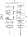
- Fig. 1 is a block diagram indicating a simplified structure of an ordinary image encoding/decoding system described in the above article.
- the reference numeral 1 denotes an A/D converter; 2 a format converter; 3 a source encoder; 4 a video multiplex encoder; 5 a transmitting controller; 6 a transmission line; 7 a receiving controller; 8 a video multiplex decoder; 9 a source decoder; 10 a format inverse-converter; and 11 a D/A converter.
- an image signal input from a TV camera, etc. is digitized by A/D converter 1, rearranged in format converter 2 into a format suitable for source encoding to form an input block.
- Source encoder 3 generates a prediction signal stream (hereinafter referred to as a prediction block) for each input block, applies an encoding algorithm to a differential signal stream (hereinafter referred to as a prediction error block) between the input block and the prediction block and thereby reduces a quantity of information.
- VLC Variable Length Codes
- Receiving controller 7 receives the multiplexed VLC data from transmission line 6 and the received data are demultiplexed and decoded in video multiplex decoder 8.
- Source decoder 9 decodes the demultiplexed data and reproduce the input block by reverse procedure of the source encoder 3.
- the decoded input block is converted to the original signal stream in format inverse-converter 10 and is then converted to an analog signal in D/A converter 11.
- An encoding algorithm except a prediction is applied to a prediction error block which acts as a differential between an input block and a prediction block to develop a prediction error block to be encoded into such encoding data as a mean value, a deviation component and a quantization-encoded value.
- These encoding data are encoded into VLC and multiplexed together with an identifier of the prediction block.
- the prediction error blocks which are confirmed "insignificant" based on the following evaluation standard are not subjected to such processing.
- Th 1 and Th 2 are significant/insignificant threshold values of the mean value and the deviation component of the prediction error block to be encoded and the quality of image to be encoded (for example, image quality and the number of transmitting frames) is controlled in accordance with these threshold values.
- the accuracy of prediction for an input block is one of the factors which give large influence on the quality of encoded image.
- a quality of encoded image is largely influenced by an amount of code information generated per frame, depending on a prediction accuracy in an input block and threshold values Th 1 and Th 2 .
- the larger an amount of code information generated the greater the quality enhancement of each frame, thus the number of transmittable frames are getting less.
- Threshold values Th 1 and Th 2 control the quantity of code information to be generated per frame as uniformly as possible so as to unify the quality of an encoded image. Therefore, if a prediction accuracy in an input block is low, the amount of code information generated in the area having a low prediction accuracy remarkably increases and threshold values Th 1 and Th 2 become large in order to control the amount of generated code information which is locally increased. Accordingly, the quality of each frame is deteriorated and the number of transmitted frames is reduced. Reduction in the number of transmitted frames results in a reduction in correlation between successive frames.
- the amount of information is reduced by utilizing a correlation between successive frames. Namely, the quality of an image to be encoded can be improved by applying motion compensated (MC) prediction between frames to prediction of an input block.
- MC motion compensated
- Fig. 2 is a diagram illustrating the concept of MC prediction.
- MC prediction a group of reference blocks consisting of a plurality of MC prediction blocks or pattern prediction blocks is prepared and the block which is the most similar to the input block is selected as a prediction block.
- the most similar prediction block is selected, for example, from the reference block group on the basis of tournament system by utilizing arithmetic distortion operation (a distortion in differential absolute value, etc.) as an evaluation function.
- tournament systems such as the total search system and multistage matching system have been proposed.
- the reference range of an MC prediction block is narrower than the total area of one frame and is often fixed in the vicinity of the same position as that of an input block. For instance, the reference range of an MC prediction block found in CCITT Recommendation H.261 is limited to within ⁇ 15 pixels for the same position of input blocks.
- Fig. 3 is a functional block diagram of format converter 2 and source encoder 3 in the conventional motion compensated (MC) predicting apparatus shown in Fig. 1.
- format converter 2 includes a block former 210 and source encoder 3 comprises an MC predicting unit 310, a high efficiency encoder 320, a local decoder 330, a frame memory 340 and a reference block generator 350.
- a digital video signal is formed into an input block by block former 210 and is then transmitted to source encoder 3.
- MC predicting unit 310 executes MC prediction for the input block.
- Reference block generator 350 accesses frame memory 340 to read a signal stream within a preset reference range as a reference block from a locally decoded signal of a preceding frame.
- a prediction error block which has been MC predicted is developed to various encoded data in high efficiency encoder 320 and are transferred to video multiplex encoder 4 and local decoder 330.
- local decoder 330 various encoded data are locally decoded in the sequence reverse to the processing performed in high efficiency encoder 320 and are stored in frame memory 340 for MC prediction of the next frame.
- An MC predicting apparatus comprises: a first means for outputting an input block by forming a block from a digital image signal stream within a frame; a second means for outputting a prediction error block by obtaining a difference between the input block and a prediction block selected from a reference block group including a plurality of prediction blocks located in the same position as or in the vicinity of the position of the input block; a third means for transforming the prediction error block to encoded data; a fourth means for adding a sequence number to each frame; and a fifth means for causing the second means to adaptively control a reference range of the reference block group in accordance with interframe correlation corresponding to a difference in sequence number of the current and preceding frames.
- the fifth means causes the second means to adaptively change the size of the reference range of the reference block group in accordance with interframe correlation.
- the number of arithmetic operations of an evaluation function for MC prediction can be reduced when the motion vectors are expected to be small and prediction accuracy can be improved when the motion vectors are expected to be big, by discriminating a sequence number of a frame to decide a correlation between the current and preceding frames on the basis of a difference in sequence number between these frames and change the size of the reference range of a prediction block depending on interframe correlation.
- the fifth means modifies a motion vector of the preceding frame in the same position as that of the input block in accordance with a difference in sequence number between the current and preceding frames, causes the second means to correct the position of the input block using such a modification as an initial displacement, thereby correcting the position of the input block as the standard position of the plurality of prediction blocks.
- redundancy of the reference range of the prediction block can be reduced by correcting the standard position of a reference range of a prediction block by a motion vector in the preceding frame and a parameter determined by a degree of correlation between the preceding and current frames.
- the fifth means causes the second means to adaptively control the standard position and the reference range of prediction block group in accordance with a difference between the sequence numbers of the current and preceding frames.
- the number of arithmetic operations of an evaluation function can be reduced and prediction accuracy against input block can be improved by adaptively controlling the standard position and the reference range of a prediction block group in accordance with a difference in sequence number of the current and preceding frames.
- Fig. 4 is an example of the structure of a source encoder in an MC predicting apparatus according to the present invention.
- reference numeral 2 denotes a format converter; 3 a source encoder; 21 a sequence number adder; 22 a block former; 31 an interframe correlation discriminator; 32 a delay; 33 an MC predicting unit; 34 a high efficiency encoder; 35 a local decoder; 36 a frame memory; 37 a reference block generator.
- a digital video signal is inputted to block former 22 and is formed therein into an input block which is in turn given a sequence number TR in sequence number adder 21 for every frame and then sent to source encoder 3.
- MC prediction is executed for the input block in MC prediction unit 33.
- Reference block generator 37 accesses frame memory 36 to cause a signal stream in a reference range to be selected from locally decoded signals of the preceding frame as a reference block.
- the reference range can be varied by adaptive control in accordance with correlation between the current and preceding frames. Correlation between the current and preceding frames can be decided by interframe correlation discriminator 31 which receives the sequence numbers of the current and preceding frames.
- the sequence number TR of the preceding frame is delayed by one frame in delay circuit 32.
- a prediction error block which has been MC predicted is transformed to various encoded data in high efficiency encoder 34 and these data are transferred to video multiplex encoder 4 and local decoder 35.
- local decoder 35 the encoded data are locally decoded in a sequence reverse to the sequence performed in high efficiency encoder 34 and are stored in frame memory 35 for MC prediction of the next frame.
- each frame is given sequence number TR corresponding to a frame rate, and a difference A between the sequence numbers of the current and preceding frames indicates a distance in time between those frames.
- an encoding process of a moving image of a moving object is taken into consideration.
- correlation self-correlation
- a distance in time between two frames gives influence on self-correlation.
- a spatial displacement of an object is approximated by a function proportional to a distance in time between frames (difference A in sequence number between frames).
- the spatial displacement of an object may be approximated by a function other than the function which is proportional to difference A in sequence number between frames.
- difference A in sequence number between the current and preceding frames is proportional to a spatial displacement of an object
- a reference range of an MC prediction block group around the same position of input blocks is enlarged or narrowed corresponding to difference A in sequence number.
- the reference range of an MC prediction block group can be enlarged or narrowed by preparing for a plurality of different reference ranges, comparing difference A in sequence number with a threshold value Ta and selecting an optimum reference range in accordance with the result of the comparison.
- Fig. 5 shows how to adaptively change two reference ranges in accordance with the present invention in comparison with a conventional reference range. This figure shows that, according to the present invention, a reference range is changed depending on whether difference A in sequence number is larger or smaller than threshold value Ta.
- the origin O of the coordinates corresponds to a standard position of the reference range of an MC prediction block group and a displacement from the standard position is made in the unit of one pixel.
- Threshold value Ta is not always a fixed parameter.
- the number of arithmetic operations using an MC prediction evaluation function can be advantageously reduced when the motion vectors are expected to be small and prediction accuracy can be improved when the motion vectors are expected to be big.
- the present example is intended to reduce a reference range in the periphery of the standard position by adequately controlling the standard position of the reference range.
- the standard position of a reference range can be obtained by compensating the same position as that of an input block by a spatial displacement component (hereinafter, referred to as an initial displacement) corresponding to difference A in sequence number.
- An initial displacement for compensation of the same position as that of an input block can be calculated from a change in time of a motion vector at the above same position and difference A between sequence numbers of the current and preceding frames.
- the motion vector to be referred to is a motion vector other than a pattern index in previous frames.
- Fig. 6 shows a concept of this control example in comparison with a conventional reference range.
- the origin O of the coordinates corresponds to the same position as that of an input block and a displacement from the standard position is made in the unit of one pixel.
- a vector from the origin O to the origin O' corresponds to an initial displacement.
- Compensation of an object which moves at uniform speed is possible by referring to the frame which is one frame preceding the current frame, and compensation taking acceleration of an object into consideration is also possible by referring to the frame which is two or more frames preceding the current frame.
- a number of the previous frames to be referred to is not required to be considered.
Landscapes
- Engineering & Computer Science (AREA)
- Multimedia (AREA)
- Signal Processing (AREA)
- Compression Or Coding Systems Of Tv Signals (AREA)
- Compression, Expansion, Code Conversion, And Decoders (AREA)
Applications Claiming Priority (3)
| Application Number | Priority Date | Filing Date | Title |
|---|---|---|---|
| JP167774/91 | 1991-06-12 | ||
| JP16777491 | 1991-06-12 | ||
| JP16777491A JP2866222B2 (ja) | 1991-06-12 | 1991-06-12 | 動き補償予測方式 |
Publications (3)
| Publication Number | Publication Date |
|---|---|
| EP0518314A2 true EP0518314A2 (de) | 1992-12-16 |
| EP0518314A3 EP0518314A3 (en) | 1993-08-11 |
| EP0518314B1 EP0518314B1 (de) | 2001-02-07 |
Family
ID=15855863
Family Applications (1)
| Application Number | Title | Priority Date | Filing Date |
|---|---|---|---|
| EP19920109813 Expired - Lifetime EP0518314B1 (de) | 1991-06-12 | 1992-06-11 | Bewegungskompensierte Prädiktionseinrichtung |
Country Status (6)
| Country | Link |
|---|---|
| US (1) | US5251030A (de) |
| EP (1) | EP0518314B1 (de) |
| JP (1) | JP2866222B2 (de) |
| AU (1) | AU658889B2 (de) |
| CA (1) | CA2070757C (de) |
| DE (1) | DE69231678T2 (de) |
Cited By (8)
| Publication number | Priority date | Publication date | Assignee | Title |
|---|---|---|---|---|
| EP0592128A2 (de) * | 1992-10-07 | 1994-04-13 | Canon Kabushiki Kaisha | Bewegungsvektordetektion und -prädiktion |
| EP0634874A2 (de) * | 1993-07-16 | 1995-01-18 | Daewoo Electronics Co., Ltd | Vorrichtung und Verfahren zur Detektion von Bewegungsvektoren in einem Bildkodierer mit Bilddezimation |
| WO1995004432A1 (en) * | 1993-07-30 | 1995-02-09 | British Telecommunications Plc | Coding image data |
| WO1995004433A1 (en) * | 1993-07-30 | 1995-02-09 | British Telecommunications Public Limited Company | Processing image data |
| EP0652678A2 (de) * | 1993-11-04 | 1995-05-10 | AT&T Corp. | Verfahren und Vorrichtung zur Verbesserung von Bewegungskompensation bei digitaler Bildkodierung |
| WO1995020863A1 (en) * | 1994-01-26 | 1995-08-03 | British Technology Group Usa Inc. | Method and apparatus for video data compression using temporally adaptive motion interpolation |
| EP0720383A1 (de) * | 1994-12-30 | 1996-07-03 | Daewoo Electronics Co., Ltd | Verfahren und Vorrichtung zur Bewegungsvektorendetektion in einem Bildkodierer mit Bilddezimation |
| AU696445B2 (en) * | 1993-07-30 | 1998-09-10 | British Telecommunications Public Limited Company | Coding image data |
Families Citing this family (18)
| Publication number | Priority date | Publication date | Assignee | Title |
|---|---|---|---|---|
| US5475446A (en) * | 1992-03-09 | 1995-12-12 | Matsushita Electric Industrial Co., Ltd. | Picture signal motion detector employing partial decimation of pixel blocks |
| EP0614317A3 (de) * | 1993-03-05 | 1995-01-25 | Sony Corp | Dekodierung von Videosignalen. |
| KR100292475B1 (ko) * | 1993-12-08 | 2001-06-01 | 구자홍 | 디지탈 영상 흔들림 보상 장치 |
| US5995670A (en) * | 1995-10-05 | 1999-11-30 | Microsoft Corporation | Simplified chain encoding |
| US5799113A (en) * | 1996-01-19 | 1998-08-25 | Microsoft Corporation | Method for expanding contracted video images |
| US5787203A (en) * | 1996-01-19 | 1998-07-28 | Microsoft Corporation | Method and system for filtering compressed video images |
| US5692063A (en) * | 1996-01-19 | 1997-11-25 | Microsoft Corporation | Method and system for unrestricted motion estimation for video |
| US5778098A (en) * | 1996-03-22 | 1998-07-07 | Microsoft Corporation | Sprite coding |
| US5764814A (en) * | 1996-03-22 | 1998-06-09 | Microsoft Corporation | Representation and encoding of general arbitrary shapes |
| US6075875A (en) * | 1996-09-30 | 2000-06-13 | Microsoft Corporation | Segmentation of image features using hierarchical analysis of multi-valued image data and weighted averaging of segmentation results |
| US5748789A (en) * | 1996-10-31 | 1998-05-05 | Microsoft Corporation | Transparent block skipping in object-based video coding systems |
| US6400831B2 (en) | 1998-04-02 | 2002-06-04 | Microsoft Corporation | Semantic video object segmentation and tracking |
| US20030023910A1 (en) * | 2001-07-25 | 2003-01-30 | Myler Harley R. | Method for monitoring and automatically correcting digital video quality by reverse frame prediction |
| EP1602240A2 (de) * | 2003-03-03 | 2005-12-07 | Mobilygen Corporation | Speicherwort-anordnung und zusammenstellung von video prädiktionsdaten zum wirksameren speicherzugriff |
| JP2006311366A (ja) * | 2005-04-28 | 2006-11-09 | Matsushita Electric Ind Co Ltd | 画像記録装置及び画像記録装置の駆動方法 |
| US7965773B1 (en) * | 2005-06-30 | 2011-06-21 | Advanced Micro Devices, Inc. | Macroblock cache |
| US8447256B2 (en) * | 2011-08-11 | 2013-05-21 | Fujitsu Semiconductor Limited | Digital voltage-controlled attenuator |
| US10085016B1 (en) | 2013-01-18 | 2018-09-25 | Ovics | Video prediction cache indexing systems and methods |
Citations (3)
| Publication number | Priority date | Publication date | Assignee | Title |
|---|---|---|---|---|
| EP0159506A2 (de) * | 1984-03-09 | 1985-10-30 | Fujitsu Limited | Gerät zur Verarbeitung eines Bildsignals mit Bandkompression |
| EP0397206A2 (de) * | 1989-05-12 | 1990-11-14 | Nec Corporation | Video-Übertragungssystem mit einer adaptiven Bild-zu-Bild-Prädiktionscodierung |
| EP0424026A2 (de) * | 1989-10-14 | 1991-04-24 | Sony Corporation | Anordnung zum Übertragen eines Videosignals |
Family Cites Families (8)
| Publication number | Priority date | Publication date | Assignee | Title |
|---|---|---|---|---|
| GB2050752B (en) * | 1979-06-07 | 1984-05-31 | Japan Broadcasting Corp | Motion compensated interframe coding system |
| US4670851A (en) * | 1984-01-09 | 1987-06-02 | Mitsubishi Denki Kabushiki Kaisha | Vector quantizer |
| AU579550B2 (en) * | 1985-06-10 | 1988-11-24 | Nec Corporation | Movement compensation predictive encoder for a moving picture signal with a reduced amount of information |
| EP0624037B1 (de) * | 1987-04-28 | 2001-10-10 | Mitsubishi Denki Kabushiki Kaisha | System zur Bildcodierung |
| JP2822454B2 (ja) * | 1989-06-02 | 1998-11-11 | 日本電気株式会社 | フレーム間予測符号化方式 |
| JP2520306B2 (ja) * | 1989-05-24 | 1996-07-31 | 三菱電機株式会社 | 変換符号化装置 |
| JPH03229586A (ja) * | 1990-02-02 | 1991-10-11 | Fujitsu Ltd | 処理量適応型の動き補償動画像符号化方式 |
| JPH0411481A (ja) * | 1990-04-28 | 1992-01-16 | Sanyo Electric Co Ltd | 画像符号化装置 |
-
1991
- 1991-06-12 JP JP16777491A patent/JP2866222B2/ja not_active Expired - Fee Related
-
1992
- 1992-06-09 CA CA 2070757 patent/CA2070757C/en not_active Expired - Fee Related
- 1992-06-10 AU AU18132/92A patent/AU658889B2/en not_active Ceased
- 1992-06-10 US US07/896,327 patent/US5251030A/en not_active Expired - Lifetime
- 1992-06-11 DE DE1992631678 patent/DE69231678T2/de not_active Expired - Fee Related
- 1992-06-11 EP EP19920109813 patent/EP0518314B1/de not_active Expired - Lifetime
Patent Citations (3)
| Publication number | Priority date | Publication date | Assignee | Title |
|---|---|---|---|---|
| EP0159506A2 (de) * | 1984-03-09 | 1985-10-30 | Fujitsu Limited | Gerät zur Verarbeitung eines Bildsignals mit Bandkompression |
| EP0397206A2 (de) * | 1989-05-12 | 1990-11-14 | Nec Corporation | Video-Übertragungssystem mit einer adaptiven Bild-zu-Bild-Prädiktionscodierung |
| EP0424026A2 (de) * | 1989-10-14 | 1991-04-24 | Sony Corporation | Anordnung zum Übertragen eines Videosignals |
Non-Patent Citations (2)
| Title |
|---|
| IEEE JOURNAL ON SELECTED AREAS IN COMMUNICATION vol. 4, no. 8, November 1986, NEW YORK US pages 1202 - 1209 H.YAMAGUCHI 'A 64kbit/s Integrated Visual Communication System - New Communication Medium for the ISDN' * |
| IEEE PROCEEDINGS OF THE SOUTHEASTCON '91 vol. 2, 7 April 1991, IEEE, NEW YORK, US; pages 1093 - 1095 Y.Q.ZHANG ET AL. 'Predictive Block-Matching Motion Estimation Schemes for Video Compression - Part II Inter-frame Prediction of Motion Vectors' * |
Cited By (16)
| Publication number | Priority date | Publication date | Assignee | Title |
|---|---|---|---|---|
| EP0592128A3 (de) * | 1992-10-07 | 1994-11-30 | Canon Kk | Bewegungsvektordetektion und -prädiktion. |
| US5787205A (en) * | 1992-10-07 | 1998-07-28 | Canon Kabushiki Kaisha | Motion vector detecting device |
| EP0592128A2 (de) * | 1992-10-07 | 1994-04-13 | Canon Kabushiki Kaisha | Bewegungsvektordetektion und -prädiktion |
| US5453801A (en) * | 1993-07-16 | 1995-09-26 | Daewoo Electronics Co. Ltd. | Method and apparatus for detecting motion vectors in a frame decimating video encoder |
| EP0634874A2 (de) * | 1993-07-16 | 1995-01-18 | Daewoo Electronics Co., Ltd | Vorrichtung und Verfahren zur Detektion von Bewegungsvektoren in einem Bildkodierer mit Bilddezimation |
| EP0634874A3 (de) * | 1993-07-16 | 1995-04-05 | Daewoo Electronics Co Ltd | Vorrichtung und Verfahren zur Detektion von Bewegungsvektoren in einem Bildkodierer mit Bilddezimation. |
| WO1995004433A1 (en) * | 1993-07-30 | 1995-02-09 | British Telecommunications Public Limited Company | Processing image data |
| WO1995004432A1 (en) * | 1993-07-30 | 1995-02-09 | British Telecommunications Plc | Coding image data |
| AU696445B2 (en) * | 1993-07-30 | 1998-09-10 | British Telecommunications Public Limited Company | Coding image data |
| US5982439A (en) * | 1993-07-30 | 1999-11-09 | British Telecommunications Public Limited Company | Coding image data |
| EP0652678A2 (de) * | 1993-11-04 | 1995-05-10 | AT&T Corp. | Verfahren und Vorrichtung zur Verbesserung von Bewegungskompensation bei digitaler Bildkodierung |
| EP0652678A3 (de) * | 1993-11-04 | 1995-09-27 | At & T Corp | Verfahren und Vorrichtung zur Verbesserung von Bewegungskompensation bei digitaler Bildkodierung. |
| WO1995020863A1 (en) * | 1994-01-26 | 1995-08-03 | British Technology Group Usa Inc. | Method and apparatus for video data compression using temporally adaptive motion interpolation |
| US5592226A (en) * | 1994-01-26 | 1997-01-07 | Btg Usa Inc. | Method and apparatus for video data compression using temporally adaptive motion interpolation |
| EP0720383A1 (de) * | 1994-12-30 | 1996-07-03 | Daewoo Electronics Co., Ltd | Verfahren und Vorrichtung zur Bewegungsvektorendetektion in einem Bildkodierer mit Bilddezimation |
| US5619281A (en) * | 1994-12-30 | 1997-04-08 | Daewoo Electronics Co., Ltd | Method and apparatus for detecting motion vectors in a frame decimating video encoder |
Also Published As
| Publication number | Publication date |
|---|---|
| AU658889B2 (en) | 1995-05-04 |
| DE69231678T2 (de) | 2001-07-05 |
| US5251030A (en) | 1993-10-05 |
| CA2070757A1 (en) | 1992-12-13 |
| JP2866222B2 (ja) | 1999-03-08 |
| CA2070757C (en) | 1998-05-26 |
| EP0518314A3 (en) | 1993-08-11 |
| JPH05227038A (ja) | 1993-09-03 |
| EP0518314B1 (de) | 2001-02-07 |
| DE69231678D1 (de) | 2001-03-15 |
| AU1813292A (en) | 1992-12-17 |
Similar Documents
| Publication | Publication Date | Title |
|---|---|---|
| US5251030A (en) | MC predicting apparatus | |
| EP0473384B1 (de) | Kodierungsgerät für digitale Bildsignale | |
| JP4528662B2 (ja) | 適応空間最新ベクトルを用いた動き検出 | |
| EP0526163B1 (de) | Verfahren und Einrichtung zur Bildkodierung | |
| US4816906A (en) | Method for motion-compensated frame-to-frame prediction coding | |
| EP0484140B1 (de) | Verfahren zur Kompression von bewegten Bildsignalen nach dem Zeilensprungverfahren | |
| US5351083A (en) | Picture encoding and/or decoding system | |
| EP0874526B1 (de) | Kodiergerät und Kodierverfahren mit Bewegungskompensation für hocheffiziente Videokodierung durch selektive Auswahl von vergangenen Bewegungsvektoren statt Benutzung von Bewegungsvektoren abgeleitet von Bewegungsschätzung | |
| EP0434427B1 (de) | Signalkodierungsgerät für bewegte Bilder | |
| EP0895425B1 (de) | Bewegungskompensierte Prädiktiv-Kodierung mit adaptiv gesteuerter Genauigkeit der Bewegungskompensation | |
| EP0637894B1 (de) | Vorrichtung und Verfahren zur Detektion von Bewegungsvektoren mit Halbpixelgenauigkeit | |
| US5327232A (en) | Method and apparatus for detecting motion vectors | |
| JP2005318620A (ja) | 適応時間予測を用いた動きベクトル検出 | |
| CA1266912A (en) | Method and apparatus for coding motion image signal | |
| EP0589504B1 (de) | System mit mindestens einem Koder zur Kodierung eines digitalen Signals und mit mindestens einem Dekoder zur Dekodierung eines digitalen Signals | |
| US6205178B1 (en) | Method and synthesizing a predicted image, video coding device and video coding method | |
| US6553068B1 (en) | Video signal coding method and device adapted to control code amounts according to the characteristics of pictures | |
| EP0529587B1 (de) | Einrichtung zur Bildkodierung | |
| US6611559B1 (en) | Apparatus and method of detecting motion vectors by calculating a correlation degree between each candidate block | |
| US6473465B1 (en) | Method and apparatus for video coding at high efficiency | |
| US6480544B1 (en) | Encoding apparatus and encoding method | |
| EP0639924B1 (de) | Kodierungsmodensteuerungsvorrichtung für digitales Bildsignalkodierungssystem | |
| US20020181589A1 (en) | Video signal coding method and coding device | |
| US20040240555A1 (en) | Device for transmitting television pictures and device for receiving said pictures | |
| JP3418799B2 (ja) | 動きベクトル補正制御方式 |
Legal Events
| Date | Code | Title | Description |
|---|---|---|---|
| PUAI | Public reference made under article 153(3) epc to a published international application that has entered the european phase |
Free format text: ORIGINAL CODE: 0009012 |
|
| AK | Designated contracting states |
Kind code of ref document: A2 Designated state(s): DE FR GB IT |
|
| PUAL | Search report despatched |
Free format text: ORIGINAL CODE: 0009013 |
|
| AK | Designated contracting states |
Kind code of ref document: A3 Designated state(s): DE FR GB IT |
|
| 17P | Request for examination filed |
Effective date: 19940204 |
|
| 17Q | First examination report despatched |
Effective date: 19961004 |
|
| GRAG | Despatch of communication of intention to grant |
Free format text: ORIGINAL CODE: EPIDOS AGRA |
|
| RIC1 | Information provided on ipc code assigned before grant |
Free format text: 7H 04N 7/32 A |
|
| GRAG | Despatch of communication of intention to grant |
Free format text: ORIGINAL CODE: EPIDOS AGRA |
|
| GRAH | Despatch of communication of intention to grant a patent |
Free format text: ORIGINAL CODE: EPIDOS IGRA |
|
| ITF | It: translation for a ep patent filed |
Owner name: INTERPATENT ST.TECN. BREV. |
|
| GRAH | Despatch of communication of intention to grant a patent |
Free format text: ORIGINAL CODE: EPIDOS IGRA |
|
| GRAA | (expected) grant |
Free format text: ORIGINAL CODE: 0009210 |
|
| AK | Designated contracting states |
Kind code of ref document: B1 Designated state(s): DE FR GB IT |
|
| REF | Corresponds to: |
Ref document number: 69231678 Country of ref document: DE Date of ref document: 20010315 |
|
| ET | Fr: translation filed | ||
| PLBE | No opposition filed within time limit |
Free format text: ORIGINAL CODE: 0009261 |
|
| STAA | Information on the status of an ep patent application or granted ep patent |
Free format text: STATUS: NO OPPOSITION FILED WITHIN TIME LIMIT |
|
| REG | Reference to a national code |
Ref country code: GB Ref legal event code: IF02 |
|
| 26N | No opposition filed | ||
| PGFP | Annual fee paid to national office [announced via postgrant information from national office to epo] |
Ref country code: DE Payment date: 20060608 Year of fee payment: 15 |
|
| PGFP | Annual fee paid to national office [announced via postgrant information from national office to epo] |
Ref country code: IT Payment date: 20060630 Year of fee payment: 15 |
|
| PG25 | Lapsed in a contracting state [announced via postgrant information from national office to epo] |
Ref country code: DE Free format text: LAPSE BECAUSE OF NON-PAYMENT OF DUE FEES Effective date: 20080101 |
|
| REG | Reference to a national code |
Ref country code: GB Ref legal event code: 746 Effective date: 20090305 |
|
| PG25 | Lapsed in a contracting state [announced via postgrant information from national office to epo] |
Ref country code: IT Free format text: LAPSE BECAUSE OF NON-PAYMENT OF DUE FEES Effective date: 20070611 |
|
| PGFP | Annual fee paid to national office [announced via postgrant information from national office to epo] |
Ref country code: GB Payment date: 20090610 Year of fee payment: 18 |
|
| GBPC | Gb: european patent ceased through non-payment of renewal fee |
Effective date: 20100611 |
|
| REG | Reference to a national code |
Ref country code: FR Ref legal event code: ST Effective date: 20110228 |
|
| PG25 | Lapsed in a contracting state [announced via postgrant information from national office to epo] |
Ref country code: FR Free format text: LAPSE BECAUSE OF NON-PAYMENT OF DUE FEES Effective date: 20100630 |
|
| PG25 | Lapsed in a contracting state [announced via postgrant information from national office to epo] |
Ref country code: GB Free format text: LAPSE BECAUSE OF NON-PAYMENT OF DUE FEES Effective date: 20100611 |
|
| PGFP | Annual fee paid to national office [announced via postgrant information from national office to epo] |
Ref country code: FR Payment date: 20090611 Year of fee payment: 18 |