EP0518227B1 - Pipe fastening clamp - Google Patents
Pipe fastening clamp Download PDFInfo
- Publication number
- EP0518227B1 EP0518227B1 EP92109518A EP92109518A EP0518227B1 EP 0518227 B1 EP0518227 B1 EP 0518227B1 EP 92109518 A EP92109518 A EP 92109518A EP 92109518 A EP92109518 A EP 92109518A EP 0518227 B1 EP0518227 B1 EP 0518227B1
- Authority
- EP
- European Patent Office
- Prior art keywords
- pipe
- semishells
- shells
- shackles
- synthetic material
- Prior art date
- Legal status (The legal status is an assumption and is not a legal conclusion. Google has not performed a legal analysis and makes no representation as to the accuracy of the status listed.)
- Expired - Lifetime
Links
Images
Classifications
-
- F—MECHANICAL ENGINEERING; LIGHTING; HEATING; WEAPONS; BLASTING
- F16—ENGINEERING ELEMENTS AND UNITS; GENERAL MEASURES FOR PRODUCING AND MAINTAINING EFFECTIVE FUNCTIONING OF MACHINES OR INSTALLATIONS; THERMAL INSULATION IN GENERAL
- F16L—PIPES; JOINTS OR FITTINGS FOR PIPES; SUPPORTS FOR PIPES, CABLES OR PROTECTIVE TUBING; MEANS FOR THERMAL INSULATION IN GENERAL
- F16L59/00—Thermal insulation in general
- F16L59/12—Arrangements for supporting insulation from the wall or body insulated, e.g. by means of spacers between pipe and heat-insulating material; Arrangements specially adapted for supporting insulated bodies
- F16L59/135—Hangers or supports specially adapted for insulated pipes
Definitions
- the invention relates to a pipe fastening clamp for cold fluid pipes with two half-shells made of thermally insulating plastic, in which steel brackets are embedded, which form radially projecting fastening tabs at the ends of the half-shells.
- the invention is based on the object of specifying a pipe fastening clamp of the generic type which makes it possible to form a fixed point which can withstand high axial forces exerted by the pipe.
- this object is achieved in that at least two steel brackets connected by axial webs are embedded in each half-shell and in that the half-shells have half-ring grooves on their inside which form a closed annular groove for receiving an annular flange provided on the pipe to be fastened in the assembled state of the half-shells .
- a permanently elastic sealing paste can be provided between the end faces of the half-shells facing each other in the assembled state, which prevents steam passage in the joint area.
- the plastic can be a surface-compressed foam that has a correspondingly high mechanical strength.
- the plastic can have a density of at least about 250 kg / m 3 and a diffusion resistance factor of at least about 2500, so that a high strength of the half-shells is ensured.
- the pipe fastening clamp shown serves for fastening a pipe 1 through which a cold fluid with a temperature of up to approximately -150 ° C. is passed. It has two half-shells 2 and 3 made of thermally insulating polyurethane foam with a density of at least about 250 kg / m 3 and a diffusion resistance factor of at least 2500, preferably more than 10000.
- Two steel brackets 4 and 5 are each embedded in the half-shells, which are connected to one another by axial webs 6, the webs 6 being welded to the steel brackets 4 and 5, respectively.
- the half-shells 2, 3 are provided on their inside with half-ring grooves 7 and 8 which, in the assembled state of the half-shells 2, 3 according to FIG. 1, form a closed annular groove for receiving an annular flange 9 (FIG. 3) provided on the pipe 1 to be fastened .
- the ring flange 9 is welded to the tube 1.
- a permanently elastic sealing paste 10 (FIG. 1) is provided between the end faces of the half-shells 2, 3 that face each other in the assembled state.
- the steel brackets 4, 5 form radially projecting fastening tabs 11 and 12 Holes 13 and 14 for the passage of connecting screws, which are also used for attachment to fixed brackets.
- the half-shells 2 and 3 are surrounded by a jacket made of two further half-shells 15 and 16 made of sheet steel, which overlap somewhat at the ends and protrude axially beyond the edge of the half-shells 2 and 3.
- the half-shells 15 and 16 form a surface protection and a vapor barrier.
- the pipe fastening clamp In the assembled state, the pipe fastening clamp withstands very high forces which endeavor to move the pipe 1 axially relative to the pipe fastening clamp. Cold or thermal bridges in the area of the pipe fastening are avoided by the insulating plastic between the supporting metal bracket arrangement and the pipe.
- the high vapor diffusion resistance eliminates the need for additional vapor barriers.
- the cross bracing of the steel brackets 4, 5 integrated in the insulation material also enables the absorption of very high axial forces.
- the sealing paste 10 prevents steam passage in the joint area.
Description
Die Erfindung bezieht sich auf eine Rohrbefestigungsschelle für kalte Fluide führende Rohre mit zwei Halbschalen aus thermisch isolierendem Kunststoff, in denen Stahlbügel eingebettet sind, die an den Enden der Halbschalen radial vorstehende Befestigungslaschen bilden.The invention relates to a pipe fastening clamp for cold fluid pipes with two half-shells made of thermally insulating plastic, in which steel brackets are embedded, which form radially projecting fastening tabs at the ends of the half-shells.
Bei einer bekannten Schelle dieser Art (DE 28 54 924 A1) kann sich das Rohr leicht in der Schelle verschieben, z.B. aufgrund thermischer Längenänderungen des Rohres, was an sogenannten "Festpunkten" der Rohrbefestigung unerwünscht ist.In a known clamp of this type (DE 28 54 924 A1) the tube can easily move in the clamp, e.g. due to thermal changes in length of the pipe, which is undesirable at so-called "fixed points" of pipe fastening.
Der Erfindung liegt die Aufgabe zugrunde, eine Rohrbefestigungsschelle der gattungsgemäßen Art anzugeben, die es ermöglicht, einen Festpunkt auszubilden, der hohen durch das Rohr ausgeübten Axialkräften standhält.The invention is based on the object of specifying a pipe fastening clamp of the generic type which makes it possible to form a fixed point which can withstand high axial forces exerted by the pipe.
Erfindungsgemäß ist diese Aufgabe dadurch gelöst, daß in jeder Halbschale wenigstens zwei durch axiale Stege verbundene Stahlbügel eingebettet sind und daß die Halbschalen auf ihrer Innenseite Halbringnuten aufweisen, die im zusammengesetzten Zustand der Halbschalen eine geschlossene Ringnut zur Aufnahme eines an dem zu befestigenden Rohr vorgesehenen Ringflansches bilden.According to the invention, this object is achieved in that at least two steel brackets connected by axial webs are embedded in each half-shell and in that the half-shells have half-ring grooves on their inside which form a closed annular groove for receiving an annular flange provided on the pipe to be fastened in the assembled state of the half-shells .
Bei dieser Ausbildung kann ein am Rohr ausgebildeter, z.B. angeschweißter, Ringflansch, der in die innere Ringnut der Schelle eingreift, eine Axialverschiebung des Rohres in der Schelle verhindern, wobei gleichzeitig die Verstrebung der Stahlbügel durch die axialen Stege die Aufnahme sehr hoher Kräfte sicherstellt. Die Aufteilung der Schelle in Halbschalen ermöglicht hierbei das Herumlegen der Halbschalen um das Rohr unter Aufnahme des Ringflansches in der Ringnut.With this design, a trained on the pipe, e.g. welded, ring flange, which engages in the inner ring groove of the clamp, prevent axial displacement of the tube in the clamp, while at the same time the bracing of the steel bracket through the axial webs ensures the absorption of very high forces. The division of the clamp into half-shells enables the half-shells to be placed around the pipe while the ring flange is accommodated in the ring groove.
Zwischen den im zusammengesetzten Zustand einander zugekehrten Stirnflächen der Halbschalen kann eine dauerelastische Dichtungspaste vorgesehen sein, die einen Dampfdurchgang im Fugenbereich vermeidet.A permanently elastic sealing paste can be provided between the end faces of the half-shells facing each other in the assembled state, which prevents steam passage in the joint area.
Bei dem Kunststoff kann es sich um einen oberflächenverdichteten Schaumstoff handeln, der eine entsprechend hohe mechanische Festigkeit aufweist.The plastic can be a surface-compressed foam that has a correspondingly high mechanical strength.
Insbesondere kann der Kunststoff eine Dichte von wenigstens etwa 250 kg/m³ und einen Diffusionswiderstandsfaktor » von wenigstens etwa 2500 aufweisen, so daß eine hohe Festigkeit der Halbschalen sichergestellt ist.In particular, the plastic can have a density of at least about 250 kg / m 3 and a diffusion resistance factor of at least about 2500, so that a high strength of the half-shells is ensured.
Sodann kann dafür gesorgt sein, daß die Halbschalen von einem Mantel aus Stahlblech umgeben sind, der axial über den Rand der Halbschalen vorsteht. Dieser Mantel bildet eine Dampfsperre und einen Oberflächenschutz.Then it can be ensured that the half-shells are surrounded by a jacket made of sheet steel, which projects axially over the edge of the half-shells. This coat forms a vapor barrier and a surface protection.
Die Erfindung und ihre Weiterbildungen werden nachstehend anhand der Zeichnung eines bevorzugten Ausführungsbeispiels näher beschrieben. Es zeigen:
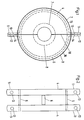
- Fig. 1 eine Seitenansicht einer erfindungsgemäßen Rohrbefestigungsschelle,
- Fig. 2 eine Vorderansicht einer in der Rohrbefestigungsschelle nach Fig. 1 eingebetteten Stahlbügelanordnung und
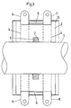
- Fig. 3 eine Hälfte der Rohrbefestigungsschelle nach Fig. 1 im montierten Zustand auf dem zu befestigenden Rohr, teilweise im Schnitt.
- 1 is a side view of a pipe fastening clamp according to the invention,
- Fig. 2 is a front view of a steel bracket assembly embedded in the pipe mounting bracket of Fig. 1 and
- Fig. 3 shows one half of the pipe fastening clamp according to Fig. 1 in the assembled state on the pipe to be fastened, partly in section.
Die dargestellte Rohrbefestigungsschelle dient zum Befestigen eines Rohres 1, durch das ein kaltes Fluid mit einer Temperatur von bis zu etwa -150°C hindurchgeleitet wird. Sie weist zwei Halbschalen 2 und 3 aus thermisch isolierendem Polyurethan-Schaumstoff mit einer Dichte von wenigstens etwa 250 kg/m³ und einen Diffusionswiderstandsfaktor » von wenigstens 2500, vorzugsweise von mehr als 10000, auf. In den Halbschalen sind jeweils zwei Stahlbügel 4 und 5 eingebettet, die durch axiale Stege 6 miteinander verbunden sind, wobei die Stege 6 an den Stahlbügeln 4 bzw. 5 angeschweißt sind. Die Halbschalen 2, 3 sind auf ihrer Innenseite mit Halbringnuten 7 und 8 versehen, die im zusammengesetzten Zustand der Halbschalen 2, 3 gemäß Fig. 1 eine geschlossene Ringnut zur Aufnahme eines an dem zu befestigenden Rohr 1 vorgesehenen Ringflansches 9 (Fig. 3) bilden. Der Ringflansch 9 ist am Rohr 1 angeschweißt.The pipe fastening clamp shown serves for fastening a
Zwischen den im zusammengesetzten Zustand einander zugekehrten Stirnflächen der Halbschalen 2, 3 ist eine dauerelastische Dichtungspaste 10 (Fig. 1) vorgesehen.A permanently elastic sealing paste 10 (FIG. 1) is provided between the end faces of the half-
An den Enden der Halbschalen 2, 3 bilden die Stahlbügel 4, 5 radial vorstehende Befestigungslaschen 11 und 12 mit Löchern 13 und 14 zur Durchführung von Verbindungsschrauben, die gleichzeitig der Befestigung an ortsfesten Haltern dienen.At the ends of the half-
Außen sind die Halbschalen 2 und 3 von einem Mantel aus zwei weiteren, sich an den Enden etwas überlappenden Halbschalen 15 und 16 aus Stahlblech umgeben, die axial über den Rand der Halbschalen 2 und 3 vorstehen. Die Halbschalen 15 und 16 bilden einen Oberflächenschutz und eine Dampfsperre.Outside, the half-
Im montierten Zustand hält die Rohrbefestigungsschelle sehr hohen Kräften stand, die bestrebt sind, das Rohr 1 axial relativ zur Rohrbefestigungsschelle zu verschieben. Kälte- bzw. Wärmebrücken im Bereich der Rohrbefestigung werden durch den isolierenden Kunststoff zwischen der tragenden Metallbügelanordnung und dem Rohr vermieden. Durch den hohen Dampfdiffusionswiderstand entfallen zusätzliche Dampfbremsen. Die Querverstrebung der im Dämmstoff integrierten Stahlbügel 4, 5 ermöglicht ebenfalls die Aufnahme sehr hoher axialer Kräfte. Die Dichtungspaste 10 verhindert einen Dampfdurchgang im Fugenbereich.In the assembled state, the pipe fastening clamp withstands very high forces which endeavor to move the
Claims (5)
- A pipe fastening clamp for pipes (1) conducting cold fluids, comprising two semishells (2, 3) of thermically isolating synthetic material, in which semishells (2, 3) steel shackles (4, 5) are embedded, the shackles providing fastening ears (11, 12) projecting radially at the ends of the semishells, characterised in that at least two steel shackles (4, 5) connected by axial bridges (6) are embedded in each semishell (2, 3), and that the semishells (2, 3) are provided at their inner sides with semi-annular grooves (7, 8) providing in the closed state of the semishells (2, 3) a closed annular groove for receiving an annular flange (9) provided at the pipe (1) to be fastened.
- The pipe of claim 1, characterised in that a permanently elastic sealing paste (10) is provided between the opposing front surfaces of the semishells (2, 3) in the assembled state.
- The pipe of claim 1 or 2, characterised in that the synthetic material is a foam material having a densified surface.
- The pipe of anyone of claims 1 to 3, characterised in that the synthetic material has a density of about 250 kg/m³ and a diffusion resitivity factor » of at least about 2500.
- The pipe of anyone of claims 1 to 4, characterised in that the semishells (2, 3) are surrounded by a sheet steel shell (15, 16) projecting axially beyond the margin of the semishells (2, 3).
Applications Claiming Priority (2)
| Application Number | Priority Date | Filing Date | Title |
|---|---|---|---|
| DE4119178 | 1991-06-11 | ||
| DE4119178A DE4119178C1 (en) | 1991-06-11 | 1991-06-11 |
Publications (2)
| Publication Number | Publication Date |
|---|---|
| EP0518227A1 EP0518227A1 (en) | 1992-12-16 |
| EP0518227B1 true EP0518227B1 (en) | 1994-09-21 |
Family
ID=6433666
Family Applications (1)
| Application Number | Title | Priority Date | Filing Date |
|---|---|---|---|
| EP92109518A Expired - Lifetime EP0518227B1 (en) | 1991-06-11 | 1992-06-05 | Pipe fastening clamp |
Country Status (2)
| Country | Link |
|---|---|
| EP (1) | EP0518227B1 (en) |
| DE (2) | DE4119178C1 (en) |
Cited By (1)
| Publication number | Priority date | Publication date | Assignee | Title |
|---|---|---|---|---|
| US7861983B2 (en) | 2005-03-22 | 2011-01-04 | Lisega Aktiengesellschaft | Cold-insulated fixed-point support |
Families Citing this family (3)
| Publication number | Priority date | Publication date | Assignee | Title |
|---|---|---|---|---|
| CN103115225A (en) * | 2013-02-11 | 2013-05-22 | 中国能源建设集团山西省电力勘测设计院 | Internal fixing knot of 150 DEG C direct burial heat-supply pipeline for preventing heat bridge transfer |
| CN106226345B (en) * | 2016-06-21 | 2020-04-10 | 中国计量科学研究院 | Quasi-adiabatic minitype gallium phase change fixed point device and measuring method |
| EP3967914A1 (en) * | 2020-09-10 | 2022-03-16 | Armacell Enterprise GmbH & Co. KG | Insulated pipe support |
Family Cites Families (7)
| Publication number | Priority date | Publication date | Assignee | Title |
|---|---|---|---|---|
| DE7837633U1 (en) * | 1978-12-20 | 1979-07-26 | Dipa - Matthias Und Rene Dick Gmbh, 5000 Koeln | PIPE CLAMP FOR PIPES CARRYING COLD MATERIALS |
| US4323088A (en) * | 1979-11-20 | 1982-04-06 | Pipe Shields, Inc. | Insulating pipe support |
| DE8615502U1 (en) * | 1986-06-09 | 1987-10-15 | Siemens Ag, 1000 Berlin Und 8000 Muenchen, De | |
| US4852831A (en) * | 1987-09-23 | 1989-08-01 | Sandstrom Wayne R | Pipe support system |
| DE3808140A1 (en) * | 1988-03-11 | 1989-09-21 | Korff & Co | Multi-part pipe clamp |
| DE3827662A1 (en) * | 1988-03-23 | 1990-02-22 | Korff & Co | Multiple-part pipe clamp |
| DE8809710U1 (en) * | 1988-07-29 | 1988-09-15 | Armstrong World Industries Gmbh, 4400 Muenster, De |
-
1991
- 1991-06-11 DE DE4119178A patent/DE4119178C1/de not_active Expired - Fee Related
-
1992
- 1992-06-05 EP EP92109518A patent/EP0518227B1/en not_active Expired - Lifetime
- 1992-06-05 DE DE59200523T patent/DE59200523D1/en not_active Expired - Fee Related
Cited By (1)
| Publication number | Priority date | Publication date | Assignee | Title |
|---|---|---|---|---|
| US7861983B2 (en) | 2005-03-22 | 2011-01-04 | Lisega Aktiengesellschaft | Cold-insulated fixed-point support |
Also Published As
| Publication number | Publication date |
|---|---|
| EP0518227A1 (en) | 1992-12-16 |
| DE4119178C1 (en) | 1993-01-21 |
| DE59200523D1 (en) | 1994-10-27 |
Similar Documents
| Publication | Publication Date | Title |
|---|---|---|
| EP0212331B1 (en) | Connection of two pipes of a hot medium conduit | |
| EP0214395B1 (en) | Elastic pipe joint, especially a flexible pipe coupling | |
| EP2146125A1 (en) | Flexible conduit pipe | |
| EP0403943B1 (en) | Thermal insulation for pipe-line compensators | |
| EP1607668A2 (en) | Refrigerant line for air conditioners | |
| DE2445055C3 (en) | Gastight soft material expansion joint | |
| EP0518227B1 (en) | Pipe fastening clamp | |
| EP3559535A1 (en) | Thermally decoupled pipe bracket with high mechanical loading capacity | |
| EP3270027B1 (en) | Pipe section with two connected jacking pipes | |
| DE19633627A1 (en) | Coupling device for the production of a pipe connection | |
| DE19631291A1 (en) | Gas flue thermal insulation system | |
| DE8606323U1 (en) | Multi-shell fireplace | |
| DE3814176C2 (en) | Double-walled pipeline made of a large number of pipe lengths connected at the ends | |
| EP0670451B1 (en) | Multi-pipe assembly | |
| EP2017523B1 (en) | Holding device for pipes | |
| DE3309930C2 (en) | ||
| EP0519313B1 (en) | Arrangement for guiding fresh air and exhaust gas | |
| DE4132740A1 (en) | Compensator fitting between two adjoining pipe ends - has clamps with closed circumferential seals to provide gastight connection | |
| DE10104046C1 (en) | Insulating hose for a pipe, comprises fleece layers of plastic fibers, where the density of the outer layer is at most equal to half the density of the inner layer | |
| EP0114269B1 (en) | Pipeline for hot fluids, and module for its assembly | |
| EP1522783B1 (en) | Insulation construction and method for the production of an insulation construction and elements therefor | |
| DE4323874A1 (en) | Fastening device for spacers on an inner tube element | |
| EP4235002A1 (en) | Thermally insulated transfer line | |
| DE3600302C2 (en) | ||
| DE3235631A1 (en) | Pipe holder |
Legal Events
| Date | Code | Title | Description |
|---|---|---|---|
| PUAI | Public reference made under article 153(3) epc to a published international application that has entered the european phase |
Free format text: ORIGINAL CODE: 0009012 |
|
| AK | Designated contracting states |
Kind code of ref document: A1 Designated state(s): BE CH DE FR GB IT LI NL SE |
|
| 17P | Request for examination filed |
Effective date: 19921211 |
|
| 17Q | First examination report despatched |
Effective date: 19940308 |
|
| GRAA | (expected) grant |
Free format text: ORIGINAL CODE: 0009210 |
|
| AK | Designated contracting states |
Kind code of ref document: B1 Designated state(s): BE CH DE FR GB IT LI NL SE |
|
| PG25 | Lapsed in a contracting state [announced via postgrant information from national office to epo] |
Ref country code: IT Free format text: LAPSE BECAUSE OF FAILURE TO SUBMIT A TRANSLATION OF THE DESCRIPTION OR TO PAY THE FEE WITHIN THE PRESCRIBED TIME-LIMIT;WARNING: LAPSES OF ITALIAN PATENTS WITH EFFECTIVE DATE BEFORE 2007 MAY HAVE OCCURRED AT ANY TIME BEFORE 2007. THE CORRECT EFFECTIVE DATE MAY BE DIFFERENT FROM THE ONE RECORDED. Effective date: 19940921 Ref country code: FR Effective date: 19940921 Ref country code: GB Effective date: 19940921 |
|
| REF | Corresponds to: |
Ref document number: 59200523 Country of ref document: DE Date of ref document: 19941027 |
|
| PG25 | Lapsed in a contracting state [announced via postgrant information from national office to epo] |
Ref country code: SE Effective date: 19941221 |
|
| EN | Fr: translation not filed | ||
| GBV | Gb: ep patent (uk) treated as always having been void in accordance with gb section 77(7)/1977 [no translation filed] |
Effective date: 19940921 |
|
| PLBE | No opposition filed within time limit |
Free format text: ORIGINAL CODE: 0009261 |
|
| STAA | Information on the status of an ep patent application or granted ep patent |
Free format text: STATUS: NO OPPOSITION FILED WITHIN TIME LIMIT |
|
| 26N | No opposition filed | ||
| PGFP | Annual fee paid to national office [announced via postgrant information from national office to epo] |
Ref country code: BE Payment date: 19970606 Year of fee payment: 6 |
|
| PGFP | Annual fee paid to national office [announced via postgrant information from national office to epo] |
Ref country code: NL Payment date: 19970630 Year of fee payment: 6 |
|
| PG25 | Lapsed in a contracting state [announced via postgrant information from national office to epo] |
Ref country code: BE Free format text: LAPSE BECAUSE OF NON-PAYMENT OF DUE FEES Effective date: 19980630 |
|
| BERE | Be: lapsed |
Owner name: MORITZ RALF Effective date: 19980630 Owner name: KORFF RAINER Effective date: 19980630 |
|
| PG25 | Lapsed in a contracting state [announced via postgrant information from national office to epo] |
Ref country code: NL Free format text: LAPSE BECAUSE OF NON-PAYMENT OF DUE FEES Effective date: 19990101 |
|
| NLV4 | Nl: lapsed or anulled due to non-payment of the annual fee |
Effective date: 19990101 |
|
| PGFP | Annual fee paid to national office [announced via postgrant information from national office to epo] |
Ref country code: CH Payment date: 19990726 Year of fee payment: 8 |
|
| PGFP | Annual fee paid to national office [announced via postgrant information from national office to epo] |
Ref country code: DE Payment date: 19990810 Year of fee payment: 8 |
|
| PG25 | Lapsed in a contracting state [announced via postgrant information from national office to epo] |
Ref country code: LI Free format text: LAPSE BECAUSE OF NON-PAYMENT OF DUE FEES Effective date: 20000630 Ref country code: CH Free format text: LAPSE BECAUSE OF NON-PAYMENT OF DUE FEES Effective date: 20000630 |
|
| REG | Reference to a national code |
Ref country code: CH Ref legal event code: PL |
|
| PG25 | Lapsed in a contracting state [announced via postgrant information from national office to epo] |
Ref country code: DE Free format text: LAPSE BECAUSE OF NON-PAYMENT OF DUE FEES Effective date: 20010403 |