EP0518210B1 - An apparatus in the cultivation of plants - Google Patents
An apparatus in the cultivation of plants Download PDFInfo
- Publication number
- EP0518210B1 EP0518210B1 EP92109439A EP92109439A EP0518210B1 EP 0518210 B1 EP0518210 B1 EP 0518210B1 EP 92109439 A EP92109439 A EP 92109439A EP 92109439 A EP92109439 A EP 92109439A EP 0518210 B1 EP0518210 B1 EP 0518210B1
- Authority
- EP
- European Patent Office
- Prior art keywords
- trough
- side wall
- side walls
- plants
- troughs
- Prior art date
- Legal status (The legal status is an assumption and is not a legal conclusion. Google has not performed a legal analysis and makes no representation as to the accuracy of the status listed.)
- Expired - Lifetime
Links
- 239000000463 material Substances 0.000 claims abstract description 24
- XLYOFNOQVPJJNP-UHFFFAOYSA-N water Substances O XLYOFNOQVPJJNP-UHFFFAOYSA-N 0.000 claims abstract description 23
- 230000015572 biosynthetic process Effects 0.000 claims abstract description 5
- 235000015097 nutrients Nutrition 0.000 claims description 7
- 239000000945 filler Substances 0.000 claims description 5
- 235000019738 Limestone Nutrition 0.000 claims description 2
- 229920001577 copolymer Polymers 0.000 claims description 2
- 239000006028 limestone Substances 0.000 claims description 2
- 239000011248 coating agent Substances 0.000 claims 2
- 238000000576 coating method Methods 0.000 claims 2
- 239000002650 laminated plastic Substances 0.000 claims 1
- 229920001384 propylene homopolymer Polymers 0.000 claims 1
- 230000000050 nutritive effect Effects 0.000 abstract description 3
- 230000001737 promoting effect Effects 0.000 abstract 1
- 241000196324 Embryophyta Species 0.000 description 36
- 239000004033 plastic Substances 0.000 description 9
- 229920003023 plastic Polymers 0.000 description 9
- 239000007788 liquid Substances 0.000 description 6
- -1 polypropylene Polymers 0.000 description 6
- 239000010410 layer Substances 0.000 description 5
- 239000004743 Polypropylene Substances 0.000 description 4
- 229920001155 polypropylene Polymers 0.000 description 4
- 238000003860 storage Methods 0.000 description 3
- 230000002349 favourable effect Effects 0.000 description 2
- 238000009434 installation Methods 0.000 description 2
- 229910052751 metal Inorganic materials 0.000 description 2
- 239000002184 metal Substances 0.000 description 2
- 238000004080 punching Methods 0.000 description 2
- 230000005855 radiation Effects 0.000 description 2
- 238000007789 sealing Methods 0.000 description 2
- 239000000126 substance Substances 0.000 description 2
- 239000000758 substrate Substances 0.000 description 2
- 240000008067 Cucumis sativus Species 0.000 description 1
- 235000010799 Cucumis sativus var sativus Nutrition 0.000 description 1
- VGGSQFUCUMXWEO-UHFFFAOYSA-N Ethene Chemical compound C=C VGGSQFUCUMXWEO-UHFFFAOYSA-N 0.000 description 1
- 239000005977 Ethylene Substances 0.000 description 1
- 235000007688 Lycopersicon esculentum Nutrition 0.000 description 1
- 239000004698 Polyethylene Substances 0.000 description 1
- 240000003768 Solanum lycopersicum Species 0.000 description 1
- 244000061458 Solanum melongena Species 0.000 description 1
- 235000002597 Solanum melongena Nutrition 0.000 description 1
- GWEVSGVZZGPLCZ-UHFFFAOYSA-N Titan oxide Chemical compound O=[Ti]=O GWEVSGVZZGPLCZ-UHFFFAOYSA-N 0.000 description 1
- 238000010521 absorption reaction Methods 0.000 description 1
- 238000009825 accumulation Methods 0.000 description 1
- 230000004075 alteration Effects 0.000 description 1
- 230000000844 anti-bacterial effect Effects 0.000 description 1
- QVGXLLKOCUKJST-UHFFFAOYSA-N atomic oxygen Chemical compound [O] QVGXLLKOCUKJST-UHFFFAOYSA-N 0.000 description 1
- 230000004888 barrier function Effects 0.000 description 1
- 230000008901 benefit Effects 0.000 description 1
- 238000009395 breeding Methods 0.000 description 1
- 230000001488 breeding effect Effects 0.000 description 1
- 239000006229 carbon black Substances 0.000 description 1
- 230000008859 change Effects 0.000 description 1
- 230000003750 conditioning effect Effects 0.000 description 1
- 238000010276 construction Methods 0.000 description 1
- 238000000151 deposition Methods 0.000 description 1
- 230000008021 deposition Effects 0.000 description 1
- 239000010459 dolomite Substances 0.000 description 1
- 229910000514 dolomite Inorganic materials 0.000 description 1
- 230000003670 easy-to-clean Effects 0.000 description 1
- 229920001519 homopolymer Polymers 0.000 description 1
- 239000011256 inorganic filler Substances 0.000 description 1
- 229910003475 inorganic filler Inorganic materials 0.000 description 1
- 239000002648 laminated material Substances 0.000 description 1
- 239000011490 mineral wool Substances 0.000 description 1
- 238000012986 modification Methods 0.000 description 1
- 230000004048 modification Effects 0.000 description 1
- 235000021049 nutrient content Nutrition 0.000 description 1
- 239000012766 organic filler Substances 0.000 description 1
- 229910052760 oxygen Inorganic materials 0.000 description 1
- 239000001301 oxygen Substances 0.000 description 1
- 229920000573 polyethylene Polymers 0.000 description 1
- QQONPFPTGQHPMA-UHFFFAOYSA-N propylene Natural products CC=C QQONPFPTGQHPMA-UHFFFAOYSA-N 0.000 description 1
- 238000000746 purification Methods 0.000 description 1
- 230000001105 regulatory effect Effects 0.000 description 1
- 239000002344 surface layer Substances 0.000 description 1
- 239000000454 talc Substances 0.000 description 1
- 229910052623 talc Inorganic materials 0.000 description 1
- 235000012222 talc Nutrition 0.000 description 1
- 229920001169 thermoplastic Polymers 0.000 description 1
- 239000004416 thermosoftening plastic Substances 0.000 description 1
- OGIDPMRJRNCKJF-UHFFFAOYSA-N titanium oxide Inorganic materials [Ti]=O OGIDPMRJRNCKJF-UHFFFAOYSA-N 0.000 description 1
- 235000013311 vegetables Nutrition 0.000 description 1
Images

Classifications
-
- A—HUMAN NECESSITIES
- A01—AGRICULTURE; FORESTRY; ANIMAL HUSBANDRY; HUNTING; TRAPPING; FISHING
- A01G—HORTICULTURE; CULTIVATION OF VEGETABLES, FLOWERS, RICE, FRUIT, VINES, HOPS OR SEAWEED; FORESTRY; WATERING
- A01G31/00—Soilless cultivation, e.g. hydroponics
- A01G31/02—Special apparatus therefor
-
- Y—GENERAL TAGGING OF NEW TECHNOLOGICAL DEVELOPMENTS; GENERAL TAGGING OF CROSS-SECTIONAL TECHNOLOGIES SPANNING OVER SEVERAL SECTIONS OF THE IPC; TECHNICAL SUBJECTS COVERED BY FORMER USPC CROSS-REFERENCE ART COLLECTIONS [XRACs] AND DIGESTS
- Y02—TECHNOLOGIES OR APPLICATIONS FOR MITIGATION OR ADAPTATION AGAINST CLIMATE CHANGE
- Y02P—CLIMATE CHANGE MITIGATION TECHNOLOGIES IN THE PRODUCTION OR PROCESSING OF GOODS
- Y02P60/00—Technologies relating to agriculture, livestock or agroalimentary industries
- Y02P60/20—Reduction of greenhouse gas [GHG] emissions in agriculture, e.g. CO2
- Y02P60/21—Dinitrogen oxide [N2O], e.g. using aquaponics, hydroponics or efficiency measures
Definitions
- the present invention relates to an apparatus in the cultivation of plants and a web-shaped blank foldable to form the apparatus according to the preamble of Claims 1 and 10, the apparatus displaying a trough with bottom, side walls and ends which together define an elongate cavity for cultivation of plants placed at the bottom of the trough.
- Cultivation troughs of this type also enjoy the advantage that damaged trough units or sections may easily be replaced by new ones which, by folding and joining, are formed from a planar blank.
- WO-A-89/04733 discloses a trough of this general type formed of metal blanks. The blanks are not continuous and kept on storage reels.
- EP-A-0300578 discloses a similar trough formed of blanks of plastic material.
- the object of the present invention is to obtain a trough of the above general type made of foldable plastic material and capable of sustaining the forces in use.
- Another object of the invention is to make it possible to adopt the size of the trough to the available space by unrolling a suitable length of a plastic web from a magazine reel.
- the blank, shown in Figs. 1 and 2, for producing a cultivation trough according to the present invention preferably consists of a foldable plastic material which is watertight and ideally displays no liquid-absorbing edges. A material particulary suited for this purpose will be discussed and described hereinbelow.
- the web 1 paid out from a storage or magazine reel 9 has three longitudinal crease lines 5 which faciltate folding and which, for example, may consist of a mechanical incision into the material, of a local attenuation of the material or some other form of processing which entails that the material readily permits folding along the crease lines 5 without rupturing in the line of fold.
- the web 1 further displays a longitudinal bottom panel 10 and a first and second side wall panel 2 and 3, respectively.
- the first side wall panel 2 is contiguous with a fixation panel 4.
- a recess 7 is provided in the second side wall panel 3, and the side wall panel 3 also displays a small hole or recess 6 which is disposed in register with a hole 6 provided in the fixation panel 4.
- Fig. 2 shows how the end portion of the web 1 may be provided with a crease line pattern 13 with whose aid an end wall can be formed in the raised trough.
- the end wall-forming panels consist of a rectangular side panel 11 and triangular panels 12 contiguous with the panel 11 and mutually connected to one another and with the remainder of the blank through crease lines 13.
- the crease lines 13 can be punched into the web 1 by means of a simple, portable punching machine in which the web end is inserted, whereafter the pattern engraved on a pressure plate is forced into the web end so that this will have the appearance as shown in Fig. 2.
- the web 1 By folding together the blank 1 along the longitudinal crease lines 5, the web 1 can be formed into a trough 18 of triangular cross-section, as shown in Fig. 3.
- the trough 18 illustrated in Fig. 3 is formed in that the side wall panels 2 and 3 are folded along the crease lines 5 and collapsed towards one another so far that their edge zones coincide.
- the fixation panel 4 which is continuous with the first side wall panel 2 is collapsed over the second side wall panel 3 in order to overlap its edge zone.
- the holes 6 provided in the side wall panel 3 and the fixation panel 4 register with one another through which holes for example an anchorage element may be passed and secured in the inserted position.
- Such an anchorage element may, for instance, consist of a plastic screw with large pitch or anchorage elements of the type which may be inserted through an oblong hole and then be locked by twisting.
- anchorage elements There is a plurality of applicable anchorage elements to choose from in order to secure the fixation panel 4 to the second side wall panel 3 and whichever is employed is of minor importance to the function of the present invention.
- trough 18 of triangular cross-section has been formed and secured in its formed state.
- the end wall panels illustrated in Fig. 2 can be raised up towards the end of the trough 18 and, by folding together of the triangular panels 12, an end wall can be formed of the type which is shown in Fig. 3. In order to retain the end wall 11 in its folded position, this may also be secured by means of an anchorage element 6 as shown in Fig. 3.
- the recesses 7 shown in Figs. 1 and 2 form, in the trough 18, window-like apertures 7' in a manner illustrated in Fig. 3. Through the apertures 7', the interior of the trough 18 is accessible from outside and plants 15 inserted in the trough 18 can grow through the apertures 7'.
- Fig.3 also shows how the trough 18 is provided with an inflow or outflow 14.
- This inflow or outflow consists of a pipe or a hose which is inserted through a hole 28 in the bottom of the trough 18, or which is inserted in the trough 18 in any other manner, e.g. through the recess 7.
- a part of this inflow or outflow 14 is shown in Fig.
- reference numeral 10 designates the bottom of the trough and a hole made in the bottom 10 of the trough is designated 28.
- a pipe 14 is passed through the hole 28 and, by providing both internal and external sealing elements 24 which, for example, may be of the type in which a rubber ring or washer disposed between a nut and a seat is compressed, the hole diameter of the rubber washer will be reduced and in such instance clamp about the pipe 14 passed through the rubber washer.
- the liquid level in the trough 18 can be regulated to the desired level.
- the inflow aperture be provided by means of a hole 28 made in the bottom 10 of the trough 18, it being sufficient to provide a hole in the end wall 11 of the trough, through which hole a hose or pipe may be inserted for the supply of water enriched with nutrients - and, as has been mentioned above, the hose may even be inserted through one of the windows 7. If this hole in the end wall of the trough is located above the liquid level in the trough 18, no sealing is required between the wall of the trough 18 and the supply pipe or hose.
- Fig. 4 shows a cross-section through the trough 18 illustrating how a plant 15 which is planted in a carrier body 16 and disposed on a plant support 17 is placed in the trough in such a manner that the roots of the plant are in contact with the water 19 running through the trough 18 for absorbing nutrients, and how the plant 15 grows out through the window 7' in the side of the triangular trough 18.
- the trough 18 displays a bottom portion 10 and two side walls 2 and 3 which slope towards one another such that the trough 18 is closed and the roots of the plant 15 are protected from external light radiation.
- the window openings 7' are only provided in the side wall panel 3, but, in certain cases, it may be advantageous alternatingly to provide the window apertures 7' in both of the side wall panels 2 and 3 so that they form a zig-zag pattern about the top edge of the trough 18. It is also possible, in a simple manner, to lock the side wall panels 2 and 3 to one another in the raised position by designing the upper portion of the window apertures of one row with a reversibly folding flap which can be folded inwardly and in such an instance lock the opposing side walls.
- Plants of this type such as cucumber, tomato, egg-plants, etc. are often sprouted in a carrier body 16 which may consist of a mineral wool cube with a side length of between 5 and 8 cm.
- This carrier body 16 with its sprouted plant is placed in the trough 18 on a plant support 17 and inserted through the window 7' in the manner illustrated in Fig. 4.
- the carrier body 16 With the aid of the plant support 17, the carrier body 16 is raised so that it does not rest on the bottom portion 10 of the trough 18 and thereby obstruct the liquid flow through the trough 18. Since the trough 18 is, in the manner illustrated, substantially enclosed, a protected environment is created for the root system of the plant 15 at the same time as the root system is protected against harmful light radiation.
- this material consists of a carrier portion 21 of a thermoplastic, preferably polypropylene, propene-homopolymer or ethylene/propene copolymer.
- This carrier layer has an admixture of an organic or inorganic filler of between 50 and 80 weight per cent.
- filler use may ideally be made of dolomitic limestone which gives no harmful depositions in the water if this were to come into contact with the carrier layer 21. Fillers such as chalk, talcum or similar materials can also be employed.
- the carrier layer 21 is further coated, preferably on both sides, with homogeneous layers 22, 23 of, for example, polypropylene plastic, and that side of the material facing towards the interior of the trough 18 may be coloured black, for example by the admixture of carbon black in the plastic layer 23, while the surface layer 22 which forms the outside of trough 18 may have an admixture of, for instance, titanium oxide which gives a white and light reflective surface in order to prevent excessively great thermal absorption in the trough 18. As a result of the black or dark-coloured inside, the root system of the plants is not heated. In the manner mentioned above, the trough 18 is fixed in position with the two mutually folded side walls 2 and 3, with the aid of the overlapping fixation panel 4 and suitable anchorage devices 20.
- the plant support 17 illustrated in Fig. 4 may preferably be manufactured from the same material as the trough 18.
- Fig. 7 shows a planar blank for such a plant support 17, and this blank (which is H-shaped) consists of four outer panels 25 which terminated in a tip 31. The panels 25 are united with a transverse panel 26. Crease lines 30 are provided in the panel 26.
- Fig. 8 is a schematic perspective view showing how the outer parts of the blank are raised to mutually parallel positions by folding along the crease lines 30, and how the carrier body 16 which carries the plant 15 is placed on the upstanding parts 25 whose tipped ends 31 are caused to penetrate into the carrier body 16. Once the carrier body 16 is placed on the plant support 17, the plant can be inserted in the trough 18 through the window 7' and be placed on the bottom 10 of the trough 18 in the manner illustrated in Fig. 4.
- a plurality of troughs 18 can be disposed in parallel with one another, the rear edges of the troughs 18 with the spillway overflow 14 being disposed adjacent a common pool or run-off channel (not shown) which may collect the water run-off from all of the troughs 18. From this pool or accumulation basin, the water can be filtered in a known manner and, after automatic analysis, enriched with nutrients to a concentration and composition suitable precisely for those plants being cultivated.
- the treated water can be pumped to conduits with the aid of which the treated water is led to the inflow apertures of the troughs 18, whereafter the water 19 may be caused to flow through the troughs 18 and, in such instance, be brought into contact with the root system of the plants 15 in order to promote the growth of the plants 15.
- the troughs 18 are made of a flexible material, they can be placed on an uneven surface, for example an earth floor, and if the substrate were to prove excessively uneven, such that large variations of the water level in the troughs 18 occur, it is a simple operation - either by adjusting the height of the troughs with substrate material or by inserting sluice gates (not shown) into the troughs - to achieve an as good as uniformly even water level.
- the above-mentioned sluice gates should be approximately of the same cross-sectional area and configuration as the trough, and the height of the sluice gates should be adapted to the desired liquid level.
- each of the troughs is provided with a bellows-folded zone (not shown) along which the troughs can, to some degree, be divided in both the vertical and lateral directions.
- bellows folds also entail that the side wall panels 2 and 3 of the troughs 18 are rigidified so that bulging of the side walls as a result of the pressure which the water in the troughs exercises on the side wall panels will be avoided or reduced.
- Inflow and outflow conduits 14 are mounted in place and the trough 18 is supported in such a manner that the liquid level in the trough will be relatively even throughout the entire length of the trough.
- water is pumped through the trough 18. Should it prove that the level differences are unacceptably great along the length of the trough, the above-mentioned sluice gates or barrier plates can be inserted in those places where the liquid level is too low.
- the prepared plants 15 (whose carrier bodies 16 have been disposed on the plant support 17) are inserted through the window apertures 7' and, by adjustment of the spillway overflow 14 of the troughs 18, a suitable water level can be adjusted such that the root systems of the inserted plants 15 will come into contact with the nutrient-enriched water.
- the troughs 18 can be opened out by removing the anchorage devices 20, 6 and laying out the troughs flat. In the flattened state, it is easy to clean the troughs 18, whereafter the flattened troughs can be nested together and stored away pending the next cultivation period.
- the apparatus according to the present invention is extremely rational and efficient and, in addition, economical.
- the system is furthermore extremely flexible, since the troughs require no permanent installations in greenhouses, it being possible instead to make the best use of that greenhouse space available, and the length of the troughs can readily be adapted to existing spaces in respect of both size and shape of the space available.
- Cultivation results achieved using the apparatus according to the present invention have proved to be extremely good, not least because the troughs 18 provide an efficient shading and a suitable environment for the root system of the plants.
- the troughs 18 be manufactured from the preferred material of polypropylene with a filler of dolomite chalk as proposed in the description, but it has proved that this material is of suitable weight and appropriate flexibility, which makes for simple handling of the troughs.
- a homogeneous plastic material of, for example, polyethylene or polypropylene has proved to be far too light in weight and far too deformable, since these materials do not possess the same degree of rigidity as a filled material.
- troughs 18 are manufactured from an unfilled plastic material, they will become more difficult to place out, they are easily dislodged from their position and easily become deformed on the application of outer stresses, in which event the passageway for the water may become obstructed.
- the plant supports 17 may also be designed in a manner different from that described above and shown on the Drawings, without, to that end, departing from the spirit and scope of the inventive concept as herein disclosed.
Landscapes
- Life Sciences & Earth Sciences (AREA)
- Environmental Sciences (AREA)
- Hydroponics (AREA)
- Cultivation Receptacles Or Flower-Pots, Or Pots For Seedlings (AREA)
- Greenhouses (AREA)
- Crystals, And After-Treatments Of Crystals (AREA)
Abstract
Description
- The present invention relates to an apparatus in the cultivation of plants and a web-shaped blank foldable to form the apparatus according to the preamble of
Claims - In rational and economical plant cultivation or breeding, it is necessary that the preconditions for the growth of the plants be stimulated in the best possible way, which is effected by a suitable supply of water, oxygen, nutrient substances, light etc., and by other external conditions such as temperature, air change etc. being as favourable as possible in order to create the correct conditions for growth.
- It is previously known, in the cultivation of vegetables, to employ troughs or channels through which water enriched with nutritive substances flows in controlled proportions. Plants which are placed out in a suitable manner in such a cultivation trough and which may be supported in pots or by other suitable means and are in contact via their root system with the flowing nutritive-enriched water will enjoy extremely favourable growth conditions, since the nutrient content in the water is always optimated and can be controlled by means of a regulator which is in turn governed by an automatic analysis instrument. It is also previously known to interconnect a plurality of cultivation troughs in series and cause the water progressively to flow through the troughs in which the plants intended for cultivation are placed.
- Prior art cultivation troughs of the type described in the foregoing have normally been made of concrete, sheet metal or similar durable materials, and an installation consisting of such troughs (or "flumes") has often constituted a permanent construction which it has not been possible to modify or adapt to suit the choice of plant varieties etc., without major alterations.
- However, it has proved desirable to be able to utilize a more flexible cultivation system, with cheap, readily joinable troughs which, when necessary, can be extended in an optional manner and in optional configurations. Cultivation troughs of this type also enjoy the advantage that damaged trough units or sections may easily be replaced by new ones which, by folding and joining, are formed from a planar blank.
- WO-A-89/04733 discloses a trough of this general type formed of metal blanks. The blanks are not continuous and kept on storage reels.
- EP-A-0300578 discloses a similar trough formed of blanks of plastic material.
- The object of the present invention is to obtain a trough of the above general type made of foldable plastic material and capable of sustaining the forces in use.
- Another object of the invention is to make it possible to adopt the size of the trough to the available space by unrolling a suitable length of a plastic web from a magazine reel.
- The above objects are attained by giving the invention the characterizing features stated in the appending claims.
- The present invention will now be described in greater detail hereinbelow, with particular reference to the accompanying schematic Drawings in which:
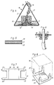
- Fig. 1 shows a web-shaped portion of the blank which is paid out from a storage or magazine reel and from which the cultivation trough is produced;
- Fig. 2 is a top plan view of the same blank which has been provided with an end embossment at the end zone of the blank;
- Fig. 3 is a perspective view of a raised and joined cultivation trough according to the present invention;
- Fig. 4 is a cross-section through the cultivation trough, with a plant inserted in place;
- Fig. 5. is a greatly magnified cross-section through the material from which the cultivation trough is produced;
- Fig. 6 shows how the passage on inflow to and outflow from the cultivation trough can be arranged;
- Fig. 7 shows a planar blank of a plant support intended to be used together with the cultivation trough; and
- Fig. 8 shows the plant support of Fig. 7 after folding formation into the active state.
- The blank, shown in Figs. 1 and 2, for producing a cultivation trough according to the present invention preferably consists of a foldable plastic material which is watertight and ideally displays no liquid-absorbing edges. A material particulary suited for this purpose will be discussed and described hereinbelow.
- Referring to Fig. 1, the
web 1 paid out from a storage or magazine reel 9 has threelongitudinal crease lines 5 which faciltate folding and which, for example, may consist of a mechanical incision into the material, of a local attenuation of the material or some other form of processing which entails that the material readily permits folding along thecrease lines 5 without rupturing in the line of fold. Theweb 1 further displays alongitudinal bottom panel 10 and a first and secondside wall panel crease lines 5, the firstside wall panel 2 is contiguous with a fixation panel 4. Arecess 7 is provided in the secondside wall panel 3, and theside wall panel 3 also displays a small hole orrecess 6 which is disposed in register with ahole 6 provided in the fixation panel 4. - Fig. 2 shows how the end portion of the
web 1 may be provided with acrease line pattern 13 with whose aid an end wall can be formed in the raised trough. The end wall-forming panels consist of arectangular side panel 11 andtriangular panels 12 contiguous with thepanel 11 and mutually connected to one another and with the remainder of the blank throughcrease lines 13. Thecrease lines 13 can be punched into theweb 1 by means of a simple, portable punching machine in which the web end is inserted, whereafter the pattern engraved on a pressure plate is forced into the web end so that this will have the appearance as shown in Fig. 2. - By folding together the blank 1 along the
longitudinal crease lines 5, theweb 1 can be formed into atrough 18 of triangular cross-section, as shown in Fig. 3. Thetrough 18 illustrated in Fig. 3 is formed in that theside wall panels crease lines 5 and collapsed towards one another so far that their edge zones coincide. In order to retain thetrough 18 in the raised configuration, the fixation panel 4 which is continuous with the firstside wall panel 2 is collapsed over the secondside wall panel 3 in order to overlap its edge zone. In this position, theholes 6 provided in theside wall panel 3 and the fixation panel 4 register with one another through which holes for example an anchorage element may be passed and secured in the inserted position. Such an anchorage element may, for instance, consist of a plastic screw with large pitch or anchorage elements of the type which may be inserted through an oblong hole and then be locked by twisting. There is a plurality of applicable anchorage elements to choose from in order to secure the fixation panel 4 to the secondside wall panel 3 and whichever is employed is of minor importance to the function of the present invention. - Once the
trough 18 of triangular cross-section has been formed and secured in its formed state. The end wall panels illustrated in Fig. 2 can be raised up towards the end of thetrough 18 and, by folding together of thetriangular panels 12, an end wall can be formed of the type which is shown in Fig. 3. In order to retain theend wall 11 in its folded position, this may also be secured by means of ananchorage element 6 as shown in Fig. 3. - The
recesses 7 shown in Figs. 1 and 2 form, in thetrough 18, window-like apertures 7' in a manner illustrated in Fig. 3. Through the apertures 7', the interior of thetrough 18 is accessible from outside andplants 15 inserted in thetrough 18 can grow through the apertures 7'. Fig.3 also shows how thetrough 18 is provided with an inflow oroutflow 14. This inflow or outflow consists of a pipe or a hose which is inserted through ahole 28 in the bottom of thetrough 18, or which is inserted in thetrough 18 in any other manner, e.g. through therecess 7. A part of this inflow oroutflow 14 is shown in Fig. 6, in whichreference numeral 10 designates the bottom of the trough and a hole made in thebottom 10 of the trough is designated 28. Apipe 14 is passed through thehole 28 and, by providing both internal andexternal sealing elements 24 which, for example, may be of the type in which a rubber ring or washer disposed between a nut and a seat is compressed, the hole diameter of the rubber washer will be reduced and in such instance clamp about thepipe 14 passed through the rubber washer. By raising or lowering thepipe 14 serving as spillway overflow, the liquid level in thetrough 18 can be regulated to the desired level. While it is practical to design both inflow and outflow aperture to the trough in the same way, it is not, however, necessary that the inflow aperture be provided by means of ahole 28 made in thebottom 10 of thetrough 18, it being sufficient to provide a hole in theend wall 11 of the trough, through which hole a hose or pipe may be inserted for the supply of water enriched with nutrients - and, as has been mentioned above, the hose may even be inserted through one of thewindows 7. If this hole in the end wall of the trough is located above the liquid level in thetrough 18, no sealing is required between the wall of thetrough 18 and the supply pipe or hose. - Fig. 4 shows a cross-section through the
trough 18 illustrating how aplant 15 which is planted in acarrier body 16 and disposed on aplant support 17 is placed in the trough in such a manner that the roots of the plant are in contact with thewater 19 running through thetrough 18 for absorbing nutrients, and how theplant 15 grows out through the window 7' in the side of thetriangular trough 18. In the fashion as described earlier, thetrough 18 displays abottom portion 10 and twoside walls trough 18 is closed and the roots of theplant 15 are protected from external light radiation. In the embodiment illustrated here, the window openings 7' are only provided in theside wall panel 3, but, in certain cases, it may be advantageous alternatingly to provide the window apertures 7' in both of theside wall panels trough 18. It is also possible, in a simple manner, to lock theside wall panels - Plants of this type, such as cucumber, tomato, egg-plants, etc. are often sprouted in a
carrier body 16 which may consist of a mineral wool cube with a side length of between 5 and 8 cm. Thiscarrier body 16 with its sprouted plant is placed in thetrough 18 on aplant support 17 and inserted through the window 7' in the manner illustrated in Fig. 4. With the aid of theplant support 17, thecarrier body 16 is raised so that it does not rest on thebottom portion 10 of thetrough 18 and thereby obstruct the liquid flow through thetrough 18. Since thetrough 18 is, in the manner illustrated, substantially enclosed, a protected environment is created for the root system of theplant 15 at the same time as the root system is protected against harmful light radiation. Fig. 5 shows a cross-section through the laminate material which may advantageously be employed in theweb 1 for producing thetrough 18. Basically, this material consists of acarrier portion 21 of a thermoplastic, preferably polypropylene, propene-homopolymer or ethylene/propene copolymer. This carrier layer has an admixture of an organic or inorganic filler of between 50 and 80 weight per cent. As filler, use may ideally be made of dolomitic limestone which gives no harmful depositions in the water if this were to come into contact with thecarrier layer 21. Fillers such as chalk, talcum or similar materials can also be employed. Thecarrier layer 21 is further coated, preferably on both sides, withhomogeneous layers trough 18 may be coloured black, for example by the admixture of carbon black in theplastic layer 23, while thesurface layer 22 which forms the outside oftrough 18 may have an admixture of, for instance, titanium oxide which gives a white and light reflective surface in order to prevent excessively great thermal absorption in thetrough 18. As a result of the black or dark-coloured inside, the root system of the plants is not heated. In the manner mentioned above, thetrough 18 is fixed in position with the two mutually foldedside walls suitable anchorage devices 20. - The
plant support 17 illustrated in Fig. 4 may preferably be manufactured from the same material as thetrough 18. Fig. 7 shows a planar blank for such aplant support 17, and this blank (which is H-shaped) consists of fourouter panels 25 which terminated in atip 31. Thepanels 25 are united with atransverse panel 26.Crease lines 30 are provided in thepanel 26. Fig. 8 is a schematic perspective view showing how the outer parts of the blank are raised to mutually parallel positions by folding along the crease lines 30, and how thecarrier body 16 which carries theplant 15 is placed on theupstanding parts 25 whose tipped ends 31 are caused to penetrate into thecarrier body 16. Once thecarrier body 16 is placed on theplant support 17, the plant can be inserted in thetrough 18 through the window 7' and be placed on the bottom 10 of thetrough 18 in the manner illustrated in Fig. 4. - A plurality of
troughs 18 can be disposed in parallel with one another, the rear edges of thetroughs 18 with thespillway overflow 14 being disposed adjacent a common pool or run-off channel (not shown) which may collect the water run-off from all of thetroughs 18. From this pool or accumulation basin, the water can be filtered in a known manner and, after automatic analysis, enriched with nutrients to a concentration and composition suitable precisely for those plants being cultivated. After possible temperature conditioning, bactericidal treatment and adjustment of pH level, the treated water can be pumped to conduits with the aid of which the treated water is led to the inflow apertures of thetroughs 18, whereafter thewater 19 may be caused to flow through thetroughs 18 and, in such instance, be brought into contact with the root system of theplants 15 in order to promote the growth of theplants 15. - Since the
troughs 18 are made of a flexible material, they can be placed on an uneven surface, for example an earth floor, and if the substrate were to prove excessively uneven, such that large variations of the water level in thetroughs 18 occur, it is a simple operation - either by adjusting the height of the troughs with substrate material or by inserting sluice gates (not shown) into the troughs - to achieve an as good as uniformly even water level. The above-mentioned sluice gates should be approximately of the same cross-sectional area and configuration as the trough, and the height of the sluice gates should be adapted to the desired liquid level. In order that the position of thetroughs 18 may easily be adjustable in the lateral or vertical positions, each of the troughs is provided with a bellows-folded zone (not shown) along which the troughs can, to some degree, be divided in both the vertical and lateral directions. These bellows folds also entail that theside wall panels troughs 18 are rigidified so that bulging of the side walls as a result of the pressure which the water in the troughs exercises on the side wall panels will be avoided or reduced. - When the
troughs 18 are to be placed out in greenhouses or on the site where cultivation is to take place, a suitable length ofweb 1 is paid out from the magazine reel 9, whereafter the web length is cut off. Using the previously mentioned portable punching machine, it is easy to punch in the end wall pattern as illustrated in Fig. 2 and, thus, in connection with the fold-formation of thetrough 18, also to form theend portions trough 18.Holes 28 for inflow and outflow are easily made using a suitable "punch pipe" and, after formation of the severedweb section 1 into atrough 18 of triangular cross-section, thetrough 18 is fixed in its position usingappropriate anchorage devices outflow conduits 14 are mounted in place and thetrough 18 is supported in such a manner that the liquid level in the trough will be relatively even throughout the entire length of the trough. After connection of inflow conduit and outflow conduit to existing systems, with purification apparatus etc., water is pumped through thetrough 18. Should it prove that the level differences are unacceptably great along the length of the trough, the above-mentioned sluice gates or barrier plates can be inserted in those places where the liquid level is too low. Finally, the prepared plants 15 (whosecarrier bodies 16 have been disposed on the plant support 17) are inserted through the window apertures 7' and, by adjustment of thespillway overflow 14 of thetroughs 18, a suitable water level can be adjusted such that the root systems of the insertedplants 15 will come into contact with the nutrient-enriched water. - When cultivation has ceased and the
plants 15 have been removed, thetroughs 18 can be opened out by removing theanchorage devices troughs 18, whereafter the flattened troughs can be nested together and stored away pending the next cultivation period. - It has proved that the apparatus according to the present invention is extremely rational and efficient and, in addition, economical. The system is furthermore extremely flexible, since the troughs require no permanent installations in greenhouses, it being possible instead to make the best use of that greenhouse space available, and the length of the troughs can readily be adapted to existing spaces in respect of both size and shape of the space available.
- Cultivation results achieved using the apparatus according to the present invention have proved to be extremely good, not least because the
troughs 18 provide an efficient shading and a suitable environment for the root system of the plants. Of course, it is not necessary that thetroughs 18 be manufactured from the preferred material of polypropylene with a filler of dolomite chalk as proposed in the description, but it has proved that this material is of suitable weight and appropriate flexibility, which makes for simple handling of the troughs. A homogeneous plastic material of, for example, polyethylene or polypropylene has proved to be far too light in weight and far too deformable, since these materials do not possess the same degree of rigidity as a filled material. If thetroughs 18 are manufactured from an unfilled plastic material, they will become more difficult to place out, they are easily dislodged from their position and easily become deformed on the application of outer stresses, in which event the passageway for the water may become obstructed. The plant supports 17 may also be designed in a manner different from that described above and shown on the Drawings, without, to that end, departing from the spirit and scope of the inventive concept as herein disclosed. - The present invention should not be considered as restricted to that described above and shown on the Drawings, many modifications being conceivable without departing from the scope of the appended Claims.
Claims (12)
- An apparatus in the cultivation of plants, comprising a trough (18) with a bottom (10), side walls (2, 3) and ends (11) which together define an elongate cavity for cultivation of plants (15) placed out on the bottom (10) of the trough (18), said bottom (10), side walls (2, 3) and ends (11, 12) being formed from a continuous planar blank (1) of a watertight material which is provided with crease lines (5, 13) facilitating folding, and the apparatus displaying, at or in the proximity of its ends (11), inflow and outflow channels (14) through which water enriched with plant nutrients may be supplied and removed, respectively, while the trough (18) is subject to throughflow by said nutrient-enriched water, the end walls display planar end walls panels (11, 12) which are contiguous with the bottom (10) and side walls (2, 3) and which, by so-called bellows folding, or other fold formation along crease lines (13), are folded together towards one another, characterized in that said side walls (2, 3) are felled to one another and, along their upper edge, interconnected with one another throughout the entire length of the trough, for the formation of a trough having triangular cross section being a roof covering the bottom portion (10).
- The apparatus as claimed in Claim 1, characterized in that the one side wall (2) displays a longitudinal fixation panel (4) which is folded down to planar abutment against the second side wall (3) and overlappingly united therewith.
- The apparatus as claimed in Claim 2, characterized in that the side walls (2, 3) are interconnected with one another by means of releasable anchorage devices (6, 20) which are operative to secure the fixation panel (4) of said one side wall (2) to the upper edge zone of said second side wall (3).
- The apparatus as claimed in Claim 1, characterized in that the roof formed by the side walls (2, 3) displays through holes or windows (7') through which the space within the trough (18) and its bottom portion (10) are accessible.
- The apparatus as claimed in Claim 4, characterized in that said holes or windows (7') are disposed in both of the side wall panels (2, 3) and are localized in such a manner that they are alternatingly disposed in the one or the other panel (2 or 3).
- The apparatus as claimed in Claim 1, characterized in that the troughs (18) are, throughout their length, provided with one or more bellows fold zones extending at right angles to the longitudinal axis of the troughs (18) and in which zones the troughs (18) can be slightly pivoted for adjusting the slope or lateral position of the trough (18).
- The apparatus as claimed in any one of the preceding Claims, characterized in that there are provided, locally along the bottom portion (10) of the trough (18), walls or barrages partially closing the cross-sectional flow area of the trough.
- The apparatus as claimed in Claim 1, characterized in that the inside of the trough (18) displays an opaque, preferably black coating, while its outside displays a reflective, preferably white coating.
- The apparatus as claimed in Claim 1, characterized in that the inlet and/or outlet of the trough (18) consists of pipes (14) at the bottom (10) of the trough (18), inserted through liquid-tight devices, said pipes being displaceable in the vertical direction.
- A web-shaped blank (1) for forming an apparatus as claimed in Claim 1, the blank (1) containing first and second side wall panels (2, 3) defined by means of crease lines (5) for forming the side walls of the trough, bottom panels (10) for forming the bottom of the trough (18) and rectangular end wall panels (11) defined at both ends of the blank (1), which are contiguous with the side wall panels (2, 3) along a plurality of mutually foldable contiguous triangular panels (12) collapsible towards one another characterized in that a fixation panel (4) pivotally united with said first side wall panel (2) and adapted to be connected to the second said wall panel (3) so as to form a trough having triangular cross section.
- The web-shaped blank as claimed in Claim 10, characterized in that it consists of a laminated plastic material comprising a layer (21) serving as carrier and comprising a propylene-homopolymer or ethylene/propylene copolymer containing between 50 and 80 weight per cent of filler.
- The web-shaped blank as claimed in Claim 11, characterized in that the filler consists of dolomitic limestone.
Applications Claiming Priority (2)
| Application Number | Priority Date | Filing Date | Title |
|---|---|---|---|
| SE9101809 | 1991-06-12 | ||
| SE9101809A SE9101809D0 (en) | 1991-06-12 | 1991-06-12 | DEVICE FOR CULTIVATION OF GROWTHS |
Publications (2)
| Publication Number | Publication Date |
|---|---|
| EP0518210A1 EP0518210A1 (en) | 1992-12-16 |
| EP0518210B1 true EP0518210B1 (en) | 1996-08-14 |
Family
ID=20383021
Family Applications (1)
| Application Number | Title | Priority Date | Filing Date |
|---|---|---|---|
| EP92109439A Expired - Lifetime EP0518210B1 (en) | 1991-06-12 | 1992-06-04 | An apparatus in the cultivation of plants |
Country Status (5)
| Country | Link |
|---|---|
| EP (1) | EP0518210B1 (en) |
| AT (1) | ATE141126T1 (en) |
| DE (1) | DE69212718T2 (en) |
| DK (1) | DK0518210T3 (en) |
| SE (1) | SE9101809D0 (en) |
Families Citing this family (4)
| Publication number | Priority date | Publication date | Assignee | Title |
|---|---|---|---|---|
| NO175081C (en) * | 1991-12-03 | 1994-08-31 | Wani Ind As | Device for harvesting utility crops, and use thereof |
| IT1292766B1 (en) * | 1997-06-11 | 1999-02-11 | Consulagri Srl | MODULAR MODULAR STRUCTURE FOR AEROPONIC CULTIVATIONS |
| EP1031276B1 (en) * | 1999-02-27 | 2003-07-30 | BRM GmbH | Device for cultivating chicory |
| TWI890587B (en) * | 2024-09-12 | 2025-07-11 | 永記造漆工業股份有限公司 | Plant positioning cultivation device |
Family Cites Families (4)
| Publication number | Priority date | Publication date | Assignee | Title |
|---|---|---|---|---|
| GB2077082A (en) * | 1980-05-27 | 1981-12-16 | Morris John Malcolm | Method and apparatus for growing crops |
| NL8701694A (en) * | 1987-07-17 | 1989-02-16 | Reko Bv | METHOD FOR MANUFACTURING A BREEDING GROW AND AN AGENT THEREFOR |
| DE3738952A1 (en) * | 1987-11-17 | 1989-05-24 | Caroe Claus J | METHOD FOR PROVIDING A LONG-STRETCHED PLANT GUTTER WITH ENDS, AND DEVICE FOR EXERCISING THE PROCESS |
| DE9004640U1 (en) * | 1990-04-25 | 1990-06-28 | E. Dittrich KG "Schlüssel"-Erzeugnisse, 2800 Bremen | Water-bearing gutter |
-
1991
- 1991-06-12 SE SE9101809A patent/SE9101809D0/en unknown
-
1992
- 1992-06-04 DK DK92109439.7T patent/DK0518210T3/en active
- 1992-06-04 DE DE69212718T patent/DE69212718T2/en not_active Expired - Fee Related
- 1992-06-04 AT AT92109439T patent/ATE141126T1/en not_active IP Right Cessation
- 1992-06-04 EP EP92109439A patent/EP0518210B1/en not_active Expired - Lifetime
Also Published As
| Publication number | Publication date |
|---|---|
| ATE141126T1 (en) | 1996-08-15 |
| DK0518210T3 (en) | 1996-11-25 |
| DE69212718T2 (en) | 1996-12-19 |
| SE9101809D0 (en) | 1991-06-12 |
| DE69212718D1 (en) | 1996-09-19 |
| EP0518210A1 (en) | 1992-12-16 |
Similar Documents
| Publication | Publication Date | Title |
|---|---|---|
| US4858378A (en) | Landscaping system | |
| US4920695A (en) | Container system for growing plants | |
| US3727345A (en) | Method of protecting plants and stimulating their growth | |
| CA2498077C (en) | Irrigation mat and method of use | |
| US20100139161A1 (en) | Self-watering plant container and related methods | |
| US20070243019A1 (en) | Gardening blanket with integral watering system | |
| JP2015522298A (en) | Organic ginseng continuous cultivation system using multi-stage cultivation floor | |
| JP2943132B2 (en) | Irrigation hose | |
| EP0222755A1 (en) | System for the water-culture of plants on a capillary substrate within a light-selective film | |
| EP0518210A1 (en) | An apparatus in the cultivation of plants | |
| US20060032116A1 (en) | Garden weed barrier and watering system | |
| DE3607772A1 (en) | Soil-carrying elements, which can be cultivated with greenery, for architecture | |
| US4463529A (en) | Combined landscaping and foundation wall protective article | |
| JP4928992B2 (en) | Bottom irrigation water supply panel, cultivation pot for the panel, and cultivation system using them | |
| JP2004097062A (en) | Medium cover film | |
| JP3050745U (en) | Elevated cultivation equipment | |
| JP2004201505A (en) | Assembly type vegetable garden room | |
| JP2004166571A (en) | High-ridge isolated bed | |
| AU600474B2 (en) | Horticultural mulch matting | |
| JP3064927B2 (en) | Elevated cultivation method and apparatus used for the method | |
| DE2748934A1 (en) | Irrigation system for plant containers - has profiled irrigation and drainage sections in lower part of vessels interconnected by unions | |
| JP3979655B2 (en) | Border processing structure of plant cultivation area | |
| JPS60184327A (en) | Culture control of plant | |
| JP4344920B2 (en) | Impermeable sheet and construction method of impermeable sheet | |
| JPH067456U (en) | Plant growing bed |
Legal Events
| Date | Code | Title | Description |
|---|---|---|---|
| PUAI | Public reference made under article 153(3) epc to a published international application that has entered the european phase |
Free format text: ORIGINAL CODE: 0009012 |
|
| AK | Designated contracting states |
Kind code of ref document: A1 Designated state(s): AT BE CH DE DK ES FR GB GR IT LI NL PT SE |
|
| 17P | Request for examination filed |
Effective date: 19930616 |
|
| 17Q | First examination report despatched |
Effective date: 19950207 |
|
| GRAG | Despatch of communication of intention to grant |
Free format text: ORIGINAL CODE: EPIDOS AGRA |
|
| GRAH | Despatch of communication of intention to grant a patent |
Free format text: ORIGINAL CODE: EPIDOS IGRA |
|
| GRAH | Despatch of communication of intention to grant a patent |
Free format text: ORIGINAL CODE: EPIDOS IGRA |
|
| GRAA | (expected) grant |
Free format text: ORIGINAL CODE: 0009210 |
|
| RAP1 | Party data changed (applicant data changed or rights of an application transferred) |
Owner name: SIMONTORP SAETERI AB |
|
| AK | Designated contracting states |
Kind code of ref document: B1 Designated state(s): AT BE CH DE DK ES FR GB GR IT LI NL PT SE |
|
| PG25 | Lapsed in a contracting state [announced via postgrant information from national office to epo] |
Ref country code: IT Free format text: LAPSE BECAUSE OF FAILURE TO SUBMIT A TRANSLATION OF THE DESCRIPTION OR TO PAY THE FEE WITHIN THE PRE;WARNING: LAPSES OF ITALIAN PATENTS WITH EFFECTIVE DATE BEFORE 2007 MAY HAVE OCCURRED AT ANY TIME BEFORE 2007. THE CORRECT EFFECTIVE DATE MAY BE DIFFERENT FROM THE ONE RECORDED.SCRIBED TIME-LIMIT Effective date: 19960814 Ref country code: FR Effective date: 19960814 Ref country code: GR Free format text: LAPSE BECAUSE OF FAILURE TO SUBMIT A TRANSLATION OF THE DESCRIPTION OR TO PAY THE FEE WITHIN THE PRESCRIBED TIME-LIMIT Effective date: 19960814 Ref country code: AT Effective date: 19960814 Ref country code: ES Free format text: THE PATENT HAS BEEN ANNULLED BY A DECISION OF A NATIONAL AUTHORITY Effective date: 19960814 Ref country code: BE Effective date: 19960814 Ref country code: LI Effective date: 19960814 Ref country code: CH Effective date: 19960814 |
|
| REF | Corresponds to: |
Ref document number: 141126 Country of ref document: AT Date of ref document: 19960815 Kind code of ref document: T |
|
| REF | Corresponds to: |
Ref document number: 69212718 Country of ref document: DE Date of ref document: 19960919 |
|
| PG25 | Lapsed in a contracting state [announced via postgrant information from national office to epo] |
Ref country code: PT Effective date: 19961114 |
|
| REG | Reference to a national code |
Ref country code: DK Ref legal event code: T3 |
|
| EN | Fr: translation not filed | ||
| REG | Reference to a national code |
Ref country code: CH Ref legal event code: PL |
|
| PLBE | No opposition filed within time limit |
Free format text: ORIGINAL CODE: 0009261 |
|
| STAA | Information on the status of an ep patent application or granted ep patent |
Free format text: STATUS: NO OPPOSITION FILED WITHIN TIME LIMIT |
|
| 26N | No opposition filed | ||
| REG | Reference to a national code |
Ref country code: GB Ref legal event code: IF02 |
|
| PGFP | Annual fee paid to national office [announced via postgrant information from national office to epo] |
Ref country code: DK Payment date: 20020521 Year of fee payment: 11 Ref country code: SE Payment date: 20020521 Year of fee payment: 11 |
|
| PGFP | Annual fee paid to national office [announced via postgrant information from national office to epo] |
Ref country code: NL Payment date: 20020522 Year of fee payment: 11 |
|
| PGFP | Annual fee paid to national office [announced via postgrant information from national office to epo] |
Ref country code: GB Payment date: 20020529 Year of fee payment: 11 |
|
| PGFP | Annual fee paid to national office [announced via postgrant information from national office to epo] |
Ref country code: DE Payment date: 20020620 Year of fee payment: 11 |
|
| PG25 | Lapsed in a contracting state [announced via postgrant information from national office to epo] |
Ref country code: GB Free format text: LAPSE BECAUSE OF NON-PAYMENT OF DUE FEES Effective date: 20030604 |
|
| PG25 | Lapsed in a contracting state [announced via postgrant information from national office to epo] |
Ref country code: SE Free format text: LAPSE BECAUSE OF NON-PAYMENT OF DUE FEES Effective date: 20030605 |
|
| PG25 | Lapsed in a contracting state [announced via postgrant information from national office to epo] |
Ref country code: DK Free format text: LAPSE BECAUSE OF NON-PAYMENT OF DUE FEES Effective date: 20030630 |
|
| PG25 | Lapsed in a contracting state [announced via postgrant information from national office to epo] |
Ref country code: DE Free format text: LAPSE BECAUSE OF NON-PAYMENT OF DUE FEES Effective date: 20040101 Ref country code: NL Free format text: LAPSE BECAUSE OF NON-PAYMENT OF DUE FEES Effective date: 20040101 |
|
| GBPC | Gb: european patent ceased through non-payment of renewal fee |
Effective date: 20030604 |
|
| EUG | Se: european patent has lapsed | ||
| REG | Reference to a national code |
Ref country code: DK Ref legal event code: EBP |
|
| NLV4 | Nl: lapsed or anulled due to non-payment of the annual fee |
Effective date: 20040101 |