EP0517249A2 - Fluid transferring apparatus imitating flapping movement of bees - Google Patents
Fluid transferring apparatus imitating flapping movement of bees Download PDFInfo
- Publication number
- EP0517249A2 EP0517249A2 EP92109552A EP92109552A EP0517249A2 EP 0517249 A2 EP0517249 A2 EP 0517249A2 EP 92109552 A EP92109552 A EP 92109552A EP 92109552 A EP92109552 A EP 92109552A EP 0517249 A2 EP0517249 A2 EP 0517249A2
- Authority
- EP
- European Patent Office
- Prior art keywords
- wing
- link
- transferring apparatus
- lever
- set forth
- Prior art date
- Legal status (The legal status is an assumption and is not a legal conclusion. Google has not performed a legal analysis and makes no representation as to the accuracy of the status listed.)
- Withdrawn
Links
Images








Classifications
-
- F—MECHANICAL ENGINEERING; LIGHTING; HEATING; WEAPONS; BLASTING
- F04—POSITIVE - DISPLACEMENT MACHINES FOR LIQUIDS; PUMPS FOR LIQUIDS OR ELASTIC FLUIDS
- F04D—NON-POSITIVE-DISPLACEMENT PUMPS
- F04D33/00—Non-positive-displacement pumps with other than pure rotation, e.g. of oscillating type
Definitions
- the present invention relates to a fluid transferring apparatus which transfers fluid with use of reciprocal motion of wings in a transverse direction in a flow passage, with imitating the flapping movement of bees.
- a cross flow fan has conventionally been used, for example, in many of the air conditioners as a fluid transferring apparatus to realize a two-dimensional flow.
- the cross flow fan is disadvantageous in its low efficiency and restrictions on design. That is, although it is effective to enlarge the diameter of a fan in order to reduce noises, a large space is necessitated therefor and a shape of a scroll part, a stabilizer or the like gives great influences upon the efficiency of the cross flow fan.
- the Weis-Fogh mechanism referred to above is for realizing a new propelling method discovered when the flapping of bees is observed.
- two wings are provided within a flow passage and moved in parallel to each other in a manner to alternately be brought close and separated in a direction orthogonal to the flow passage, while an attack angle of each wing is changed at both ends of its stroke.
- the object of the present invention is therefore to provide a fluid transferring apparatus which, realizing the Weis-Fogh mechanism by a mechanism simple in structure and able to operate at high speeds, achieves a second-dimensional flow with high efficiency and with reduced noises.
- a fluid transferring apparatus which comprises: a casing defining a flow passage of fluid; a wing assembly having at least one wing provided in a transverse direction of the flow passage; and a driving mechanism for moving the wing in a manner similar to when bees are flapping.
- the casing and the flow passage are rectangular in cross section.
- the driving mechanism is provided in the vicinity of the casing and in a peripheral section of the flow passage.
- the driving mechanism is a crank mechanism consisting of a rotating crank, a crank pin, a guide member extending in a transverse direction of the flow passage, a slider guided by the guide member to slide in a transverse direction of the flow passage, and a link having one end thereof rotatably coupled to the crank pin and the other end thereof rotatably coupled by a pin to the slider, and the wing of the wing assembly is mounted to the link of the crank mechanism.
- the link is reciprocated in a direction approximately orthogonal to the flow passage while an inclining angle of the link is continuously changed as the crank is rotated by a motor, for example.
- the wing is reciprocated in a direction transverse to the flow passage from a top dead point to a bottom dead point while an inclining angle of the wing (namely, an attack angle) to the flow in the flow passage is continuously changed as the crank is rotated, whereby the fluid is transferred by the surface of the wing, that is to say, the air is supplied in a blower.
- the wing of the wing assembly is fixed to the link.
- the wing assembly has a plurality of wings which are parallel to each other and are fixed to the link.
- the wing is formed of flexible material, a front end of which is fixed to the link.
- a front end of the wing is rotatably mounted to the link in a manner that a predetermined force is necessary to rotate the wing to the link.
- a front end of the wing is rotatably mounted to the link by a pin, while a rear end of the wing is coupled to the link by a spring, thereby to control an angle of attack of the wing.
- a front end of the wing is rotatably mounted to the link by a pin, while a rear end of the wing is coupled to the link by a leader, thereby to control an angle of attack of the wing.
- a plurality of units each comprised of the crank mechanism and wing assembly are provided at both the upstream and the downstream sides of the flow passage, with rotational phase angles being made different among the cranks of the crank mechanisms in the plurality of units when the cranks are driven.
- a plurality of wing assemblies different in the operating phase are provided in the front of and in the rear of the flow passage, so that pulsation of transferring fluid can be restricted as much as possible, with a higher static pressure ensured, in comparison with the case where a single wing assembly is used. As a result, the fluid is transferred more stably with improved efficiency.
- a plurality of units each comprised of the crank mechanism and wing assembly are provided in a transverse direction of the flow passage.
- the units adjacent to each other are arranged in symmetric relation and driven in reverse rotational phase.
- the driving mechanism is a crank mechanism consisting of a rotating link, a crank pin, a first link rotatably mounted at a fulcrum and a second link having one end thereof rotatably mounted to the crank pin and the other end thereof rotatably mounted to an end of the first link by a pin, and wherein the wing of the wing assembly is mounted to the second link.
- the driving mechanism includes a swinging lever mounted to a shaft extending in a direction to traverse the flow passage, and wherein a front end of the wing of the wing assembly is mounted to the lever.
- the front end of the wing is mounted to the lever in a rotatable manner.
- a rear end of the wing is coupled to the lever with a spring, thereby to control an angle of attack of the wing.
- a rear end of the wing is coupled to the lever by a leader, thereby to control an angle of attack of the wing.
- the wing is formed of flexible material.
- the wing is formed of flexible material and mounted to the lever in a manner unable to rotate, with the wing extending along a center line of the lever in the natural state.
- a central part of the lever is mounted to the shaft in a manner able to swing, with front ends of the wings being mounted to either end of the lever.
- the wings are formed of flexible material and have a front end fixed to either end of the lever, and the wings extend along a center line of the lever, with a rear end directed in a downstream direction of the flow passage in the natural state.
- the lever is a T-shaped figure having a projecting part which projects from a central part of the lever
- the driving mechanism is a crank mechanism consisting of the T-shaped lever, a rotating crank, a crank pin, and a link having one end thereof rotatably mounted to the crank pin and the other end thereof rotatably mounted to an end of the projecting part by a pin.
- the driving mechanism is a crank mechanism consisting of the lever, a crank, a crank pin and a link having one end thereof rotatably mounted to the crank pin and the other end thereof rotatably mounted to the lever by a pin.
- the other end of the link is rotatably mounted to an end of the lever where the wing is mounted.
- a groove is formed in the lever, and the driving mechanism is a crank mechanism consisting of the lever, a rotating crank, and a crank pin sliding in the groove of the lever.
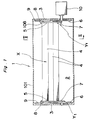
- a fan 1 as a fluid transferring apparatus according to a first embodiment of the present invention.
- the fan 1 realizes a second-dimensional flow of a fluid with high efficiency at low level of noise by simulating a so-called Weis-Fogh mechanism with use of a mechanism simple in structure and able to operate at high speeds.
- the fan 1 is provided with a wing assembly X to be described later which is arranged within a flow passage 2 of a rectangular cross section defined by a casing 101 of a rectangular cross section and, a crank mechanism Y to be described later which reciprocates each wing of the wing assembly X in a transverse direction of the flow passage while an attack angle of the wing is changed.
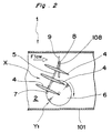
- the wing assembly X has three wings 4, 4, .., each with a predetermined chord length in a streamlined cross section, aligned in parallel in a thicknesswise direction of the wings with a predetermined distance.
- Each wing 4, 4, .. of the wing assembly X is mounted within the flow passage 2 in a direction crossing the flow passage in a widthwise direction while both ends of the wing are supported by the crank mechanism Y1.
- Both surfaces of each wing 4, 4, .. are selectively turned to be a positive pressure face and therefore, each wing is a symmetric wing having a symmetric cross section to the chord of the wing.
- the crank mechanism Y1 referred to above is constituted of a disk-shaped crank 6 supported rotatably in a lower part of a side wall 3 of the flow passage 2, a slider 8 slidably supported to a guide rail 9 which extends in a vertical direction of the fan 1 in an upper part of the side wall 3 to be overlapped with the crank 6 in the vertical direction, and a link 5 of a predetermined length having one end coupled to an outer peripheral edge of the crank 6 via a crank pin 7 and the other end coupled relatively rotatably to the slider 8 by a pin 108.
- the rotational motion of the crank 6 is transmitted to the slider 8 via the link 5 as the reciprocal movement of the slider 8 in the vertical direction of the fan 1.
- the crank mechanism Y1 of the above-described structure is provided respectively at each side wall 3 of the flow passage 2.
- One crank mechanism Y1 is driven directly by a motor 10, while the other crank mechanism Y1 is driven by the one crank mechanism Y1 via the wing assembly X.
- the crank mechanisms Y1, Y1 are synchronously driven by respective motors 10, 10 so as to lessen the force impressed to each wing 4, 4, ...
- each wing 4, 4, .. of the wing assembly X are fixed to the links 5, 5 of the crank mechanisms Y, Y1 at the right and left side walls 3, 3 of the flow passage 2.
- each wing is mounted approximately with 90° to the link 5 in order that the attack angle of the wing 4 to the fluid in the flow passage 2 (i.e., transferring efficiency of the wing 4) becomes equal to each other between when the crank pin 7 is moved from a top dead point to a bottom dead point and when the crank pin 7 is moved from a bottom dead point to a top dead point.
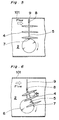
- Fig. 3 which illustrates a first driving step
- the crank pin 7 is at the bottom dead point
- each wing 4 of the wing assembly X is held in parallel to the flow of the fluid in the lower part of the flow passage 2. Therefore, the resistance to the flow by the wings 4, 4, .. is reduced as much as possible.
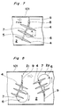
- Fig. 7 shows a modified embodiment of the fan 1 of Fig. 1. More specifically, as compared with the first embodiment wherein the crank pin 7 is provided at one end of the link 5, the crank pin 7 is set in the middle of the link 5 in this modified embodiment. In the structure of Fig. 7, if the oscillating angle of the link 5 is the same as in Fig. 1, the crank 6 becomes smaller in diameter, so that the fan 1 can be made compact in size.
- Fig. 8 is a cross sectional view of a fan 1 according to a second embodiment of the present invention.
- a fan unit one unit of the wing assembly X and crank mechanism Y1 coupled to the wing assembly X (referred to as a fan unit hereinafter) is provided in the first embodiment, there are provided two fan units Z1, Z2 at both the upstream and the downstream sides of the flow passage 2 in the second embodiment. These fan units Z1, Z2 are mounted reverse to each other in the vertical direction and rotated in the reverse phase.
- Fig. 9 is a modified example of Fig. 8, wherein two fan units Z1, Z2 are arranged in the same vertical direction (i.e., two or more pairs of the fan unit of the first embodiment are arranged with a predetermined distance).
- the rotational direction is made the same, but the rotational phase difference is suitably set. Accordingly, the pulsation in the air flow is restrained and the static pressure is kept large.
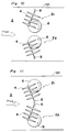
- a fan of a third embodiment of the present invention is, as indicated in Fig. 10, so constituted that two fan units Z1, Z2 are provided up and down to traverse the flow passage 2.
- the fan units Z1, Z2 are symmetric to a direction of the air flow.
- the cranks 6, 6 adjacent to each other are driven in the reverse direction, that is, in the reverse phase, thereby to transfer the air. Accordingly, the transferring amount of the air is increased.
- Fig. 11 is a modification of the fan of Fig. 10, which is different from Fig. 10 in that the sliders 8, 8 are provided adjacent to each other.
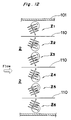
- FIG. 12 there are six fan units Z1, Z2, Z3, .. Z6 provided in a transverse direction of the flow passage 2.
- the adjacent two fan units are symmetric to each other to the flow of the flow passage 2, and driven in the reverse phase.
- a numeral 110 designates a flow rectifier plate.
- a fan according to a fourth embodiment of the present invention is shown in Fig. 13.
- a crank mechanism Y2 of Fig. 13 is constituted of a crank 6, a crank pin 7, a first link 116 mounted rotatably to a fulcrum 115 and a second link 5 having one end thereof rotatably mounted to the crank pin 7 and the other end thereof rotatably provided to an end of the first link 116 by a pin 117.
- the crank mechanism Y2 operates as a quadric crank chain.
- a driving mechanism Y3 is comprised of a shaft 201 extending in a direction intersecting the flow passage 2 and a lever 202.
- the lever 202 is swayed at its center around the shaft 201 by a swing motor (not shown), although it is possible to swing the lever 202 by a crank mechanism, as described later.
- a front end part of each wing 4 is mounted to each end of the lever 202 by a pin 203, so that the wing 4 is rotated when receiving a predetermined force which is set, for instance, by adjusting the friction force between the pin 203 and wing 4.
- the swinging motion of the lever 202 causes the wings 4, 4 to move similarly to the flapping bees.
- the horizontal wing 4 receives a repulsive force from the fluid thereby to rotate upwards, and vice versa.
- Fig. 17 is a modified example of Fig. 14, in which a rear end of the wing 4 is coupled to the lever 202 by a coil spring 205 so that the attack angle of the wing 4 is held within 30°.
- the attack angle may be within 45°.
- a frond end or a center part of the wing 4 may be coupled to the lever 202 by a coil spring, although it is not in figures.
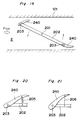
- a wing 240 is formed of flexible material, and this is a sole difference from Fig. 14.
- the lever 202 is rotated in a direction of an arrow, the wing 240 is bent as shown in Fig. 19 since it is formed of flexible material.18
- wing 4 of Figs. 17 and 18 is replaced with a flexible wing 240, respectively.
- each wing 240 is formed of flexible material, a front end part of which is rigidly fixed to an end of the lever 202 by a fixing pin 213 in a manner not to be rotatable. In the natural state, the wings 240 extend along the center line of the lever 202 and moreover, rear end parts of the wings 240 are directed in the same downstream direction.
- the wings 240 are moved in a manner similar to when the bees are flapping. That is, referring to Figs. 23 and 24, when the horizontal wing 240 is moved downward, it receives a repulsive force from the fluid and is accordingly rotated upward as indicated in Fig. 24. The same goes true if the wing 240 is moved in the opposite direction.
- Fig. 25 is a modification of Fig. 22, wherein a rear end of the wing 240 and the lever 202 are coupled with each other by a coil spring 205, so that the attack angle of the wing 240 is kept within 30°. However, the attack angle of the wing 240 may be held within 45°.
- a front end or a center part of the wing 260 may be coupled to the lever 202 by either a coil spring or a leader.
- Fig. 27 represents an eighth embodiment of the present invention.
- the eighth embodiment is different from the first embodiment of Figs. 1 and 2 only in that a front end part of the wing 240 made of flexible material is fixed to the link 5.
- a T-shaped lever 222 of a fan has a projecting part 222a which projects in a direction perpendicular to the central part of the lever 222.
- a crank mechanism Y3 consists of the T-shaped lever 222, a rotary crank 60, a crank pin 7 and a link 5.
- One end of the link 5 is rotatably mounted to the crank pin 7, while the other end of the link 5 is rotatably mounted to a front end of the projecting part 222a of the lever 222 by a pin 108.
- the crank mechanism Y3 operates in the same manner as in the fifth embodiment shown in Figs. 14-16.
- a coil spring 205 is utilized so as to control the attack angle of the wing 4.
- a reference numeral 219 in Fig. 29 denotes a bearing which supports a shaft 201.
- the wing 4 is allowed to flap like bees by a crank mechanism Y4.
- the crank mechanism Y4 is comprised of a lever 202 supported at a fulcrum 201 in a swinging fashion, a crank 60, a crank pin 7 and a link 301 with one end rotatably mounted to the crank pin 7 and the other end rotatably mounted at the intermediate point between a front end and the center of the lever 202 by a pin 299.
- the operation of the crank mechanism Y4 is the same as the crank mechanism Y3 in the fifth embodiment shown in Figs. 14-16.
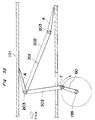
- Fig. 32 is a modification of Fig. 31.
- An end of a link 302 is coupled to an end of the lever 202 by a pin 203 so as to prevent the end of the lever 202 from oscillating.
- the crank 60 is disposed outside the casing 101 so as to reduce resistance against a flow.
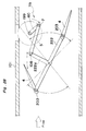
- a crank mechanism Y5 of a fan is comprised of a lever 302 having a groove 302a and swinging at a fulcrum 201, a rotating crank 60, and a crank pin 7 sliding in the groove 302a of the lever 302.
- the wings 4 are moved in such a manner as if bees were flapping.
- the wing assembly X is constituted of two or three sheets of wings 4, 4, .. in any of the foregoing embodiments, the present invention is not restricted to this number of wings, and the number of wings may be set suitably corresponding to the desired transferring amount of air or static pressure, etc. It is needless to say that the wing assembly X may be formed of four or more wings, or a single sheet of wing may be provided at either of the upstream and downstream sides of the lever. Moreover, the chord length of the wing may be set suitably.
- the fluid transferring apparatus of the present invention is embodied in fan in the description hereinabove.
- the present invention is applicable, for example, to a pump or the like.
Landscapes
- Engineering & Computer Science (AREA)
- Mechanical Engineering (AREA)
- General Engineering & Computer Science (AREA)
- Structures Of Non-Positive Displacement Pumps (AREA)
Abstract
The present invention provides a fluid transferring apparatus which achieves a second-dimensional flow of fluid with high efficiency and at low noise by imitating a Weis-Fogh mechanism with use of a simple mechanism. In the fluid transferring apparatus, a wing assembly X comprising a predetermined number of plate-like wings 4 is provided in a transverse direction of a flow passage 2. The wing assembly X is supported by a link 5 of a crank mechanism Y1 which consists of a crank 6 rotated by a motor, a slider 8 slidable in a direction orthogonal to a direction of a flow in a flow passage 2 , the link 5 coupling the crank 6 with the slider 8, so that rotational motion of the crank 6 is transmitted to the slider 8 as a reciprocal movement. While an angle of attack of each wing 4 is changed by the oscillating action of the link 5, each wing 4 is moved in a transverse direction of the flow passage 2 as the link 5 is reciprocated, thereby achieving transfer of fluid.
Description
- The present invention relates to a fluid transferring apparatus which transfers fluid with use of reciprocal motion of wings in a transverse direction in a flow passage, with imitating the flapping movement of bees.
- A cross flow fan has conventionally been used, for example, in many of the air conditioners as a fluid transferring apparatus to realize a two-dimensional flow. In comparison with a propeller fan, a sirocco fan, etc. which achieves a three-dimensional flow, however, the cross flow fan is disadvantageous in its low efficiency and restrictions on design. That is, although it is effective to enlarge the diameter of a fan in order to reduce noises, a large space is necessitated therefor and a shape of a scroll part, a stabilizer or the like gives great influences upon the efficiency of the cross flow fan.
- Therefore, a fluid transferring apparatus of a perfectly new type has been desired and a proposal for utilization of a so-called Weis-Fogh mechanism, e.g., as disclosed in Japanese Patent Laid-open Publication 64-107000 has been made to realize a second-dimensional flow with high efficiency and reduced noises.
- In the meantime, the Weis-Fogh mechanism referred to above is for realizing a new propelling method discovered when the flapping of bees is observed. As indicated in the above-mentioned prior art as well, according to the Weis-Fogh mechanism, two wings are provided within a flow passage and moved in parallel to each other in a manner to alternately be brought close and separated in a direction orthogonal to the flow passage, while an attack angle of each wing is changed at both ends of its stroke.
- However, a driving mechanism would be considerably complicate and hard to operate at high speeds if the wings were driven by mechanical means strictly in compliance with the Weis-Fogh mechanism. Therefore, no suitable example of actual application of the Weis-Fogh mechanism has been embodied so far, and the above prior art also does not clearly disclose a concrete driving mechanism, thus calling for a technique enabling realization of the Weis-Fogh mechanism in a simple manner.
- The object of the present invention is therefore to provide a fluid transferring apparatus which, realizing the Weis-Fogh mechanism by a mechanism simple in structure and able to operate at high speeds, achieves a second-dimensional flow with high efficiency and with reduced noises.
- In order to accomplish the above-described object, there is provided a fluid transferring apparatus which comprises:
a casing defining a flow passage of fluid;
a wing assembly having at least one wing provided in a transverse direction of the flow passage; and
a driving mechanism for moving the wing in a manner similar to when bees are flapping. - It is preferable that the casing and the flow passage are rectangular in cross section.
- Further, it is preferable that the driving mechanism is provided in the vicinity of the casing and in a peripheral section of the flow passage.
- Furthermore, it is preferable that the driving mechanism is a crank mechanism consisting of a rotating crank, a crank pin, a guide member extending in a transverse direction of the flow passage, a slider guided by the guide member to slide in a transverse direction of the flow passage, and a link having one end thereof rotatably coupled to the crank pin and the other end thereof rotatably coupled by a pin to the slider, and the wing of the wing assembly is mounted to the link of the crank mechanism.
- With the above structure, the link is reciprocated in a direction approximately orthogonal to the flow passage while an inclining angle of the link is continuously changed as the crank is rotated by a motor, for example. Accordingly, the wing is reciprocated in a direction transverse to the flow passage from a top dead point to a bottom dead point while an inclining angle of the wing (namely, an attack angle) to the flow in the flow passage is continuously changed as the crank is rotated, whereby the fluid is transferred by the surface of the wing, that is to say, the air is supplied in a blower.
- Thus, a pseudo Weis-Fogh mechanism is presented in the fluid transferring apparatus of the present invention, and therefore a second-dimensional flow can be positively and easily obtained with high efficiency and low noise. At the same time, since the crank mechanism itself is simple in structure and able to work at high speeds, it is easily applied to an actual transferring apparatus. Moreover, the transferring direction of a fluid can be changed with ease by controlling the rotational phase of the crank mechanism. Therefore, it is highly effective particularly when the fluid transferring apparatus of the present invention is applied to an air conditioner fan.
- Further, it is preferable that the wing of the wing assembly is fixed to the link.
- Further, it is preferable that the wing assembly has a plurality of wings which are parallel to each other and are fixed to the link.
- Furthermore, it is preferable that the wing is formed of flexible material, a front end of which is fixed to the link.
- Further, it is preferable that a front end of the wing is rotatably mounted to the link in a manner that a predetermined force is necessary to rotate the wing to the link.
- Further, it is preferable that a front end of the wing is rotatably mounted to the link by a pin, while a rear end of the wing is coupled to the link by a spring, thereby to control an angle of attack of the wing.
- Moreover, it is preferable that a front end of the wing is rotatably mounted to the link by a pin, while a rear end of the wing is coupled to the link by a leader, thereby to control an angle of attack of the wing.
- Further, it is preferable that a plurality of units each comprised of the crank mechanism and wing assembly are provided at both the upstream and the downstream sides of the flow passage, with rotational phase angles being made different among the cranks of the crank mechanisms in the plurality of units when the cranks are driven.
- With the above structure, a plurality of wing assemblies different in the operating phase are provided in the front of and in the rear of the flow passage, so that pulsation of transferring fluid can be restricted as much as possible, with a higher static pressure ensured, in comparison with the case where a single wing assembly is used. As a result, the fluid is transferred more stably with improved efficiency.
- Further, it is preferable that a plurality of units each comprised of the crank mechanism and wing assembly are provided in a transverse direction of the flow passage.
- Further, it is preferable that the units adjacent to each other are arranged in symmetric relation and driven in reverse rotational phase.
- Further, it is preferable that the driving mechanism is a crank mechanism consisting of a rotating link, a crank pin, a first link rotatably mounted at a fulcrum and a second link having one end thereof rotatably mounted to the crank pin and the other end thereof rotatably mounted to an end of the first link by a pin, and wherein the wing of the wing assembly is mounted to the second link.
- Moreover, it is preferable that the driving mechanism includes a swinging lever mounted to a shaft extending in a direction to traverse the flow passage, and wherein a front end of the wing of the wing assembly is mounted to the lever.
- Further, it is preferable that the front end of the wing is mounted to the lever in a rotatable manner.
- Further, it is preferable that a rear end of the wing is coupled to the lever with a spring, thereby to control an angle of attack of the wing.
- Further, it is preferable that a rear end of the wing is coupled to the lever by a leader, thereby to control an angle of attack of the wing.
- Furthermore, it is preferable that the wing is formed of flexible material.
- Further, it is preferable that the wing is formed of flexible material and mounted to the lever in a manner unable to rotate, with the wing extending along a center line of the lever in the natural state.
- Further, it is preferable that a central part of the lever is mounted to the shaft in a manner able to swing, with front ends of the wings being mounted to either end of the lever.
- Further, it is preferable that the wings are formed of flexible material and have a front end fixed to either end of the lever, and the wings extend along a center line of the lever, with a rear end directed in a downstream direction of the flow passage in the natural state.
- Further, it is preferable that the lever is a T-shaped figure having a projecting part which projects from a central part of the lever, and wherein the driving mechanism is a crank mechanism consisting of the T-shaped lever, a rotating crank, a crank pin, and a link having one end thereof rotatably mounted to the crank pin and the other end thereof rotatably mounted to an end of the projecting part by a pin.
- Furthermore, it is preferable that the driving mechanism is a crank mechanism consisting of the lever, a crank, a crank pin and a link having one end thereof rotatably mounted to the crank pin and the other end thereof rotatably mounted to the lever by a pin.
- Further, it is preferable that the other end of the link is rotatably mounted to an end of the lever where the wing is mounted.
- Further, it is preferable that a groove is formed in the lever, and the driving mechanism is a crank mechanism consisting of the lever, a rotating crank, and a crank pin sliding in the groove of the lever.
- These and other objects and features of the present invention will become clear from the following description taken in conjunction with the preferred embodiments thereof with reference to the accompanying drawings throughout which like parts are designated by like reference numerals, and in which:
- Fig. 1 is a front view of a fan according to a first embodiment of the present invention;
- Fig. 2 is a cross sectional view taken on line II-II of Fig. 1;
- Figs. 3-6 are explanatory diagrams of the operation of the fan of Fig. 1;
- Fig. 7 is a cross sectional view of a modified example of the fan of Fig. 1;
- Fig. 8 is a cross sectional view of a fan according to a second embodiment of the present invention;
- Fig. 9 is a cross sectional view of a modification of the fan of Fig. 8;
- Fig. 10 is a cross sectional view of a fan according to a third embodiment of the present invention;
- Figs. 11 and 12 are cross sectional views of modifications of the fan of Fig. 10;
- Fig. 13 is a cross sectional view of a fan according to a fourth embodiment of the present invention;
- Fig. 14 is a cross sectional view of a fan according to a fifth embodiment of the present invention;
- Figs. 15 and 16 are explanatory diagrams of the fan of Fig. 14;
- Figs. 17 and 18 are diagrams of modifications of the fan of Fig. 14;
- Fig. 19 is a cross sectional view of a fan according to a sixth embodiment of the present invention;
- Figs. 20 and 21 are explanatory diagrams of modifications of the fan of Fig. 19;
- Fig. 22 is a cross sectional view of a fan according to a seventh embodiment of the present invention;
- Figs. 23 and 24 are explanatory diagrams of the fan of Fig. 22;
- Figs. 25 and 26 are diagrams of modifications of the fan of Fig. 22;
- Fig. 27 is a cross sectional view of a fan according to an eighth embodiment of the present invention;
- Fig. 28 is a cross sectional view of a fan according to a ninth embodiment of the present invention;
- Figs. 29 and 30 are a front view and a cross sectional view of a modification of the fan of Fig. 28;
- Fig. 31 is a cross sectional view of a fan according to a tenth embodiment of the present invention;
- Fig. 32 is a cross sectional view of a variation of the fan of Fig. 31; and
- Fig. 33 is a cross sectional view of a fan according to an 11th embodiment of the present invention.
- Now, a fluid transferring apparatus according to preferred embodiments of the present invention will be discussed in detail with reference to the accompanying drawings.
- In Figs. 1 and 2, there is shown a
fan 1 as a fluid transferring apparatus according to a first embodiment of the present invention. Thefan 1 realizes a second-dimensional flow of a fluid with high efficiency at low level of noise by simulating a so-called Weis-Fogh mechanism with use of a mechanism simple in structure and able to operate at high speeds. Thefan 1 is provided with a wing assembly X to be described later which is arranged within aflow passage 2 of a rectangular cross section defined by acasing 101 of a rectangular cross section and, a crank mechanism Y to be described later which reciprocates each wing of the wing assembly X in a transverse direction of the flow passage while an attack angle of the wing is changed. - The wing assembly X has three
wings wing flow passage 2 in a direction crossing the flow passage in a widthwise direction while both ends of the wing are supported by the crank mechanism Y1. Both surfaces of eachwing - The crank mechanism Y1 referred to above is constituted of a disk-shaped
crank 6 supported rotatably in a lower part of aside wall 3 of theflow passage 2, aslider 8 slidably supported to aguide rail 9 which extends in a vertical direction of thefan 1 in an upper part of theside wall 3 to be overlapped with thecrank 6 in the vertical direction, and alink 5 of a predetermined length having one end coupled to an outer peripheral edge of thecrank 6 via acrank pin 7 and the other end coupled relatively rotatably to theslider 8 by apin 108. The rotational motion of thecrank 6 is transmitted to theslider 8 via thelink 5 as the reciprocal movement of theslider 8 in the vertical direction of thefan 1. - According to the first embodiment, the crank mechanism Y1 of the above-described structure is provided respectively at each
side wall 3 of theflow passage 2. One crank mechanism Y1 is driven directly by amotor 10, while the other crank mechanism Y1 is driven by the one crank mechanism Y1 via the wing assembly X. Needless to say, such a modified arrangement is possible, for example, if the wing assembly is relatively long, that the crank mechanisms Y1, Y1 are synchronously driven byrespective motors wing - Right and left ends of each
wing links side walls flow passage 2. In this case, each wing is mounted approximately with 90° to thelink 5 in order that the attack angle of thewing 4 to the fluid in the flow passage 2 (i.e., transferring efficiency of the wing 4) becomes equal to each other between when thecrank pin 7 is moved from a top dead point to a bottom dead point and when thecrank pin 7 is moved from a bottom dead point to a top dead point. - The driving state of the
above fan 1 will be described with reference to Figs. 3-6. Referring first to Fig. 3 which illustrates a first driving step, thecrank pin 7 is at the bottom dead point, and eachwing 4 of the wing assembly X is held in parallel to the flow of the fluid in the lower part of theflow passage 2. Therefore, the resistance to the flow by thewings - When the first step is changed to a second step shown in Fig. 4 as the
crank 6 is rotated in a direction of an arrow by themotor 10, thelink 5 of the crank mechanism Y1 is inclined upward in the forward direction of the flow, with the inclining angle being continuously changed. Accordingly, eachwing 4 of the wing assembly X supported by thislink 5 is moved to the upper part of theflow passage 2 crossing theflow passage 2 while the attack angle at the upper surface of the wing ϑ1 is continuously changed. In consequence, the air is transferred. This feeding action of the air is continued until thecrank pin 7 reaches a top dead point in a third step (referring to Fig. 5). When thecrank pin 7 reaches the top dead point, the feeding action by the wing is stopped. However, each wing is turned in parallel to the flow in theflow passage 2 and therefore gives little resistance to the flow of the air obtained so far. Accordingly, the pulsation in the air flow is prevented as much as possible. - When the
crank 6 is further rotated and thecrank pin 7 is moved from the top dead point to the bottom dead point in a fourth step (referring to Fig. 6), thelink 5 of the crank mechanism Y1 is inclined downward in the forward direction of the flow and the inclining angle of thelink 5 is continuously changed. As a result, eachwing 4 of the wing assembly X is moved downward while the attack angle at the lower surface of the wing ϑ1 is continuously changed, thereby performing a transfer of the air. The air is kept feeding until thecrank pin 7 is returned to the bottom dead point again (referring to Fig. 3). - As the wings of the wing assembly X are reciprocated by the crank mechanisms Y1, Y1 in the vertical direction within the
flow passage 2 while the attack angles of the wings are continuously changed as described hereinabove, the continuous transfer of the air is thus achieved. - Fig. 7 shows a modified embodiment of the
fan 1 of Fig. 1. More specifically, as compared with the first embodiment wherein thecrank pin 7 is provided at one end of thelink 5, thecrank pin 7 is set in the middle of thelink 5 in this modified embodiment. In the structure of Fig. 7, if the oscillating angle of thelink 5 is the same as in Fig. 1, thecrank 6 becomes smaller in diameter, so that thefan 1 can be made compact in size. - Fig. 8 is a cross sectional view of a
fan 1 according to a second embodiment of the present invention. Although one unit of the wing assembly X and crank mechanism Y1 coupled to the wing assembly X (referred to as a fan unit hereinafter) is provided in the first embodiment, there are provided two fan units Z1, Z2 at both the upstream and the downstream sides of theflow passage 2 in the second embodiment. These fan units Z1, Z2 are mounted reverse to each other in the vertical direction and rotated in the reverse phase. - In the above-described structure, since the air is fed by two fan units Z1, Z2, i.e., the air is pressured in two stages, a larger static pressure is obtained, as compared with the case that only one fan unit is used. Moreover, since the two units Z1, Z2 are rotated reverse in phase, the pulsation in the air flow is more restricted, thereby realizing a stable flow of the air.
- Fig. 9 is a modified example of Fig. 8, wherein two fan units Z1, Z2 are arranged in the same vertical direction (i.e., two or more pairs of the fan unit of the first embodiment are arranged with a predetermined distance). The rotational direction is made the same, but the rotational phase difference is suitably set. Accordingly, the pulsation in the air flow is restrained and the static pressure is kept large.
- A fan of a third embodiment of the present invention is, as indicated in Fig. 10, so constituted that two fan units Z1, Z2 are provided up and down to traverse the
flow passage 2. The fan units Z1, Z2 are symmetric to a direction of the air flow. Thecranks - Fig. 11 is a modification of the fan of Fig. 10, which is different from Fig. 10 in that the
sliders - In a further modification shown in Fig. 12, there are six fan units Z1, Z2, Z3, .. Z6 provided in a transverse direction of the
flow passage 2. The adjacent two fan units are symmetric to each other to the flow of theflow passage 2, and driven in the reverse phase. A numeral 110 designates a flow rectifier plate. - A fan according to a fourth embodiment of the present invention is shown in Fig. 13. A crank mechanism Y2 of Fig. 13 is constituted of a
crank 6, acrank pin 7, afirst link 116 mounted rotatably to afulcrum 115 and asecond link 5 having one end thereof rotatably mounted to the crankpin 7 and the other end thereof rotatably provided to an end of thefirst link 116 by apin 117. - The crank mechanism Y2 operates as a quadric crank chain.
- In a fifth embodiment of a fan shown in Fig. 14, a driving mechanism Y3 is comprised of a
shaft 201 extending in a direction intersecting theflow passage 2 and alever 202. Thelever 202 is swayed at its center around theshaft 201 by a swing motor (not shown), although it is possible to swing thelever 202 by a crank mechanism, as described later. A front end part of eachwing 4 is mounted to each end of thelever 202 by apin 203, so that thewing 4 is rotated when receiving a predetermined force which is set, for instance, by adjusting the friction force between thepin 203 andwing 4. - The swinging motion of the
lever 202 causes thewings pin 203 is moved downward, thehorizontal wing 4 receives a repulsive force from the fluid thereby to rotate upwards, and vice versa. - Fig. 17 is a modified example of Fig. 14, in which a rear end of the
wing 4 is coupled to thelever 202 by acoil spring 205 so that the attack angle of thewing 4 is held within 30°. The attack angle may be within 45°. In addition, a frond end or a center part of thewing 4 may be coupled to thelever 202 by a coil spring, although it is not in figures. - In Fig. 18, the
coil spring 205 of Fig. 17 is replaced with aleader 206. - According to a sixth embodiment of a fan of Fig. 19, a
wing 240 is formed of flexible material, and this is a sole difference from Fig. 14. When thelever 202 is rotated in a direction of an arrow, thewing 240 is bent as shown in Fig. 19 since it is formed of flexible material.18 - In Figs. 20 and 21, the
wing 4 of Figs. 17 and 18 is replaced with aflexible wing 240, respectively. - As indicated in Fig. 22, according to a seventh embodiment of the present invention, each
wing 240 is formed of flexible material, a front end part of which is rigidly fixed to an end of thelever 202 by a fixingpin 213 in a manner not to be rotatable. In the natural state, thewings 240 extend along the center line of thelever 202 and moreover, rear end parts of thewings 240 are directed in the same downstream direction. - As the
lever 202 is swinged, thewings 240 are moved in a manner similar to when the bees are flapping. That is, referring to Figs. 23 and 24, when thehorizontal wing 240 is moved downward, it receives a repulsive force from the fluid and is accordingly rotated upward as indicated in Fig. 24. The same goes true if thewing 240 is moved in the opposite direction. - Fig. 25 is a modification of Fig. 22, wherein a rear end of the
wing 240 and thelever 202 are coupled with each other by acoil spring 205, so that the attack angle of thewing 240 is kept within 30°. However, the attack angle of thewing 240 may be held within 45°. - Further in Fig. 26, the
coil spring 205 of Fig. 25 is replaced with aleader 206. - Further, alternatively, a front end or a center part of the wing 260 may be coupled to the
lever 202 by either a coil spring or a leader. - Fig. 27 represents an eighth embodiment of the present invention. The eighth embodiment is different from the first embodiment of Figs. 1 and 2 only in that a front end part of the
wing 240 made of flexible material is fixed to thelink 5. - Referring to Fig. 28, a T-shaped
lever 222 of a fan according to a ninth embodiment of the present invention has a projecting part 222a which projects in a direction perpendicular to the central part of thelever 222. A crank mechanism Y3 consists of the T-shapedlever 222, a rotary crank 60, acrank pin 7 and alink 5. One end of thelink 5 is rotatably mounted to the crankpin 7, while the other end of thelink 5 is rotatably mounted to a front end of the projecting part 222a of thelever 222 by apin 108. The crank mechanism Y3 operates in the same manner as in the fifth embodiment shown in Figs. 14-16. - In a modified embodiment of Figs. 29 and 30, a
coil spring 205 is utilized so as to control the attack angle of thewing 4. Areference numeral 219 in Fig. 29 denotes a bearing which supports ashaft 201. - According to a tenth embodiment shown in Fig. 31, the
wing 4 is allowed to flap like bees by a crank mechanism Y4. The crank mechanism Y4 is comprised of alever 202 supported at afulcrum 201 in a swinging fashion, acrank 60, acrank pin 7 and alink 301 with one end rotatably mounted to the crankpin 7 and the other end rotatably mounted at the intermediate point between a front end and the center of thelever 202 by apin 299. The operation of the crank mechanism Y4 is the same as the crank mechanism Y3 in the fifth embodiment shown in Figs. 14-16. - Fig. 32 is a modification of Fig. 31. An end of a
link 302 is coupled to an end of thelever 202 by apin 203 so as to prevent the end of thelever 202 from oscillating. Also, thecrank 60 is disposed outside thecasing 101 so as to reduce resistance against a flow. - As shown in Fig. 33, a crank mechanism Y5 of a fan according to an 11th embodiment of the present invention is comprised of a
lever 302 having agroove 302a and swinging at afulcrum 201, a rotating crank 60, and a crankpin 7 sliding in thegroove 302a of thelever 302. Thewings 4 are moved in such a manner as if bees were flapping. - Although the wing assembly X is constituted of two or three sheets of
wings - The fluid transferring apparatus of the present invention is embodied in fan in the description hereinabove. However, the present invention is applicable, for example, to a pump or the like.
- Although the present invention has been fully described in connection with the preferred embodiments thereof with reference to the accompanying drawings, it is to be noted that various changes and modifications are apparent to those skilled in the art. Such changes and modifications are to be understood as included within the scope of the present invention as defined by the appended claims unless they depart therefrom.
Claims (26)
- A fluid transferring apparatus which comprises:
a casing defining a flow passage of fluid;
a wing assembly having at least one wing provided in a transverse direction of the flow passage; and
a driving mechanism for moving the wing in a manner similar to when bees are flapping. - A fluid transferring apparatus as set forth in claim 1, wherein the casing and the flow passage are rectangular in cross section.
- A fluid transferring apparatus as set forth in claim 1, wherein the driving mechanism is provided in the vicinity of the casing and in a peripheral section of the flow passage.
- A fluid transferring apparatus as set forth in claim 1, wherein the driving mechanism is a crank mechanism consisting of a rotating crank, a crank pin, a guide member extending in a transverse direction of the flow passage, a slider guided by the guide member to slide in a transverse direction of the flow passage, and a link having one end thereof rotatably coupled to the crank pin and the other end thereof rotatably coupled by a pin to the slider, and wherein the wing of the wing assembly is mounted to the link of the crank mechanism.
- A fluid transferring apparatus as set forth in claim 4, wherein the wing of the wing assembly is fixed to the link.
- A fluid transferring apparatus as set forth in claim 4, wherein the wing assembly has a plurality of wings which are parallel to each other and are fixed to the link.
- A fluid transferring apparatus as set forth in claim 5, wherein the wing is formed of flexible material, a front end of which is fixed to the link.
- A fluid transferring apparatus as set forth in claim 4, wherein a front end of the wing is rotatably mounted to the link in a manner that a predetermined force is necessary to rotate the wing to the link.
- A fluid transferring apparatus as set forth in claim 4, wherein a front end of the wing is rotatably mounted to the link by a pin, while the wing is coupled to the link by a spring, thereby to control an angle of attack of the wing.
- A fluid transferring apparatus as set forth in claim 4, wherein a front end of the wing is rotatably mounted to the link by a pin, while the wing is coupled to the link by a leader, thereby to control an angle of attack of the wing.
- A fluid transferring apparatus as set forth in claim 4, wherein a plurality of units each comprised of the crank mechanism and wing assembly are provided at both the upstream and the downstream sides of the flow passage, with rotational phase angles being made different among the cranks of the crank mechanisms in the plurality of units when the cranks are driven.
- A fluid transferring apparatus as set forth in claim 4, wherein a plurality of units each comprised of the crank mechanism and wing assembly are provided in a transverse direction of the flow passage.
- A fluid transferring apparatus as set forth in claim 12, wherein the units adjacent to each other are arranged in symmetric relation and driven in reverse rotational phase.
- A fluid transferring apparatus as set forth in claim 1, wherein the driving mechanism is a crank mechanism consisting of a rotating link, a crank pin, a first link rotatably mounted at a fulcrum and a second link having one end thereof rotatably mounted to the crank pin and the other end thereof rotatably mounted to an end of the first link by a pin, and wherein the wing of the wing assembly is mounted to the second link.
- A fluid transferring apparatus as set forth in claim 1, wherein the driving mechanism includes a swinging lever mounted to a shaft extending in a direction to traverse the flow passage, and wherein a front end of the wing of the wing assembly is mounted to the lever.
- A fluid transferring apparatus as set forth in claim 15, wherein the front end of the wing is mounted to the lever in a rotatable manner.
- A fluid transferring apparatus as set forth in claim 16, wherein the wing is coupled to the lever with a spring, thereby to control an angle of attack of the wing.
- A fluid transferring apparatus as set forth in claim 16, wherein the wing is coupled to the lever by a leader, thereby to control an angle of attack of the wing.
- A fluid transferring apparatus as set forth in one of the claims 16 to 18, wherein the wing is formed of flexible material.
- A fluid transferring apparatus as set forth in claim 15, wherein the wing is formed of flexible material and mounted to the lever in a manner unable to rotate, with the wing extending along a center line of the lever in the natural state.
- A fluid transferring apparatus as set forth in claim 15, wherein a central part of the lever is mounted to the shaft in a manner able to swing, with front ends of the wings being mounted to either end of the lever.
- A fluid transferring apparatus as set forth in claim 21, wherein the wings are formed of flexible material and have a front end fixed to either end of the lever, and wherein the wings extend along a center line of the lever, with a rear end directed in a downstream direction of the flow passage in the natural state.
- A fluid transferring apparatus as set forth in claim 22, wherein the lever is a T-shaped figure having a projecting part which projects from a central part of the lever, and wherein the driving mechanism is a crank mechanism consisting of the T-shaped lever, a rotating crank, a crank pin, and a link having one end thereof rotatably mounted to the crank pin and the other end thereof rotatably mounted to an end of the projecting part by a pin.
- A fluid transferring apparatus as set forth in claim 15, wherein the driving mechanism is a crank mechanism consisting of the lever, a crank, a crank pin and a link having one end thereof rotatably mounted to the crank pin and the other end thereof rotatably mounted to the lever by a pin.
- A fluid transferring apparatus as set forth in claim 24, wherein the other end of the link is rotatably mounted to an end of the lever where the wing is mounted.
- A fluid transferring apparatus as set forth in claim 15, wherein a groove is formed in the lever, and the driving mechanism is a crank mechanism consisting of the lever, a rotating crank, and a crank pin sliding in the groove of the lever.
Applications Claiming Priority (2)
| Application Number | Priority Date | Filing Date | Title |
|---|---|---|---|
| JP136704/91 | 1991-06-07 | ||
| JP13670491 | 1991-06-07 |
Publications (2)
| Publication Number | Publication Date |
|---|---|
| EP0517249A2 true EP0517249A2 (en) | 1992-12-09 |
| EP0517249A3 EP0517249A3 (en) | 1993-03-10 |
Family
ID=15181534
Family Applications (1)
| Application Number | Title | Priority Date | Filing Date |
|---|---|---|---|
| EP19920109552 Withdrawn EP0517249A3 (en) | 1991-06-07 | 1992-06-05 | Fluid transferring apparatus imitating flapping movement of bees |
Country Status (3)
| Country | Link |
|---|---|
| US (1) | US5302092A (en) |
| EP (1) | EP0517249A3 (en) |
| CA (1) | CA2070574A1 (en) |
Cited By (7)
| Publication number | Priority date | Publication date | Assignee | Title |
|---|---|---|---|---|
| DE4405544A1 (en) * | 1994-02-22 | 1996-03-07 | Friedrich Berner | Pulse jet drive for use in liquid or gaseous environments |
| WO2000053935A1 (en) | 1999-03-11 | 2000-09-14 | Robert Spillner | Method and devices for producing a fluid current |
| EP1258637A1 (en) * | 2001-05-14 | 2002-11-20 | Ludwig Resch | 'Bird wing' pump |
| GB2376720A (en) * | 2001-06-20 | 2002-12-24 | 1 Ltd | Fluid-propelling device |
| WO2007045447A1 (en) * | 2005-10-19 | 2007-04-26 | Erfinde Gmbh | Fluid mechanical converter |
| US7431244B2 (en) | 2002-08-14 | 2008-10-07 | Siemens Aktiengesellschaft | Device for the generation of eddies and method for operating of said device |
| CN105416533A (en) * | 2015-12-24 | 2016-03-23 | 佛山市神风航空科技有限公司 | Annular plate blade ship propelling device provided with linear motor |
Families Citing this family (5)
| Publication number | Priority date | Publication date | Assignee | Title |
|---|---|---|---|---|
| FR2808916B1 (en) * | 2000-05-11 | 2003-08-15 | Jean Laurent Peube | ELECTROAEROACOUSTIC SOURCE AND SYSTEM FOR ACTIVE NOISE CONTROL |
| US20100196181A1 (en) * | 2009-02-02 | 2010-08-05 | Alizarov Zhobbar | Pump Device |
| US10054105B2 (en) * | 2012-04-30 | 2018-08-21 | Just the 4 of Us, LLC | Dolphin-blade, fluid flow, reciprocal motor |
| US20140193258A1 (en) * | 2013-01-09 | 2014-07-10 | Asia Vital Components Co., Ltd. | Swing fan structure |
| CN112823862A (en) * | 2019-11-20 | 2021-05-21 | 中国商用飞机有限责任公司 | Manual glue mixing device |
Family Cites Families (19)
| Publication number | Priority date | Publication date | Assignee | Title |
|---|---|---|---|---|
| US12190A (en) * | 1855-01-09 | Improved propeller | ||
| DE153810C (en) * | ||||
| GB191309600A (en) * | 1912-10-18 | 1914-01-15 | Franz Blicharski | Improvements in Means for Propelling and Steering Ships. |
| GB157381A (en) * | 1919-02-15 | 1922-05-10 | Heinrich Schieferstein | Improvements in or relating to the propulsion of fluids by means of oscillating fan like elements |
| US1601246A (en) * | 1924-07-03 | 1926-09-28 | Frost Christian | Water and air fan |
| FR844617A (en) * | 1938-10-12 | 1939-07-28 | Propulsion device for boats, boats, swimmers | |
| GB588953A (en) * | 1945-03-12 | 1947-06-06 | Donald Vivian Hotchkiss | Improvements relating to the propulsion of watercraft |
| CH289372A (en) * | 1948-03-20 | 1953-03-15 | Mueller Hans | Device for moving a liquid by means of a vibrating organ. |
| US2728298A (en) * | 1952-07-11 | 1955-12-27 | Homer J Shafer | Vessel and fluid propelling device |
| US3048141A (en) * | 1960-12-23 | 1962-08-07 | Fisk John Edwin | Propulsion device for craft in fluids |
| FR1418806A (en) * | 1964-03-09 | 1965-11-26 | Device for propelling or pumping a fluid and application of this device to the propulsion of ships | |
| FR1472317A (en) * | 1966-03-08 | 1967-03-10 | Device for propelling or pumping liquids or gases | |
| CH493363A (en) * | 1968-05-11 | 1970-07-15 | Hirmann Georg | Method and device for propelling a watercraft |
| DE1728084A1 (en) * | 1968-08-22 | 1972-03-09 | Flygt Pumpen Gmbh | Lifting and conveying device for sewage or the like. |
| DE2446964A1 (en) * | 1974-10-02 | 1976-04-08 | Jean Joubert | Pump for liquids has housing and flat paddle - driven to oscillate and swivel inside housing |
| GB1577582A (en) * | 1977-12-02 | 1980-10-29 | Hey M C V | Oscillatory pump |
| EP0043877A1 (en) * | 1980-07-14 | 1982-01-20 | Russell Richard Ferrers Wakelin | Method and apparatus for displacing fluids by means of an oscillating blade |
| JPH01107000A (en) * | 1987-10-19 | 1989-04-24 | Michihisa Tsutahara | Pump applied flapping mechanism of bee |
| JPH03160200A (en) * | 1989-11-15 | 1991-07-10 | Kenji Oe | Air blower |
-
1992
- 1992-06-04 US US07/894,271 patent/US5302092A/en not_active Expired - Fee Related
- 1992-06-05 CA CA002070574A patent/CA2070574A1/en not_active Abandoned
- 1992-06-05 EP EP19920109552 patent/EP0517249A3/en not_active Withdrawn
Cited By (10)
| Publication number | Priority date | Publication date | Assignee | Title |
|---|---|---|---|---|
| DE4405544A1 (en) * | 1994-02-22 | 1996-03-07 | Friedrich Berner | Pulse jet drive for use in liquid or gaseous environments |
| WO2000053935A1 (en) | 1999-03-11 | 2000-09-14 | Robert Spillner | Method and devices for producing a fluid current |
| DE19910731A1 (en) * | 1999-03-11 | 2000-09-14 | Robert Spillner | Method and device for a turbomachine with reciprocating parts |
| EP1258637A1 (en) * | 2001-05-14 | 2002-11-20 | Ludwig Resch | 'Bird wing' pump |
| GB2376720A (en) * | 2001-06-20 | 2002-12-24 | 1 Ltd | Fluid-propelling device |
| GB2376720B (en) * | 2001-06-20 | 2005-08-31 | 1 Ltd | Fluid-propelling device |
| US7431244B2 (en) | 2002-08-14 | 2008-10-07 | Siemens Aktiengesellschaft | Device for the generation of eddies and method for operating of said device |
| WO2007045447A1 (en) * | 2005-10-19 | 2007-04-26 | Erfinde Gmbh | Fluid mechanical converter |
| US7914258B2 (en) | 2005-10-19 | 2011-03-29 | Bionic Motion Gmbh | Fluid mechanical converter |
| CN105416533A (en) * | 2015-12-24 | 2016-03-23 | 佛山市神风航空科技有限公司 | Annular plate blade ship propelling device provided with linear motor |
Also Published As
| Publication number | Publication date |
|---|---|
| CA2070574A1 (en) | 1992-12-08 |
| US5302092A (en) | 1994-04-12 |
| EP0517249A3 (en) | 1993-03-10 |
Similar Documents
| Publication | Publication Date | Title |
|---|---|---|
| US5302092A (en) | Fluid transferring apparatus imitating flapping movement of bees | |
| US4260328A (en) | Windmill | |
| JPS62294779A (en) | Valveless positive-motion displacement weighing pump | |
| EP0953765A3 (en) | Variable displacement type swash plate compressor and displacement control valve | |
| CN114889407B (en) | Air outlet blade adjustment mechanism, electric air outlet assembly and vehicle | |
| CN107014052A (en) | One kind pendulum wind mechanism and air conditioner | |
| CN109110106B (en) | Actuator assembly for deploying an aircraft leading edge flap and seal for an aircraft leading edge flap | |
| CN112172121A (en) | A linear double station alternately in and out laminating platform for laminating equipment | |
| CN112128141B (en) | Snail tongue structure, wall mounted unit and air conditioner | |
| CN2757218Y (en) | Computer ssytem air guide device | |
| US11781631B2 (en) | Magnetic drive motor assembly and associated method of use | |
| CN205098477U (en) | Differential change width of cloth flapping wing actuating mechanism | |
| CN101229069A (en) | Even pace fan-shaped scan running device of type-B ultrasonic | |
| CN204254841U (en) | Air-conditioning and exhaust apparatus thereof | |
| CN118701262A (en) | A variable-rigidity flapping-wing underwater robotic fish and its working method | |
| JPH05180199A (en) | Fluid feeding device | |
| CN118323429B (en) | Control rudder face angle linkage device and method thereof | |
| JP3008347B1 (en) | Servo mounting structure for aileron of helicopter toy | |
| CN220689324U (en) | Electric air valve and ventilation system | |
| JP2016536508A (en) | Apparatus and method for propelling gases, fluids, and objects using a tail cycle | |
| CN223013183U (en) | Parallel type movement mechanism | |
| JPH0347167Y2 (en) | ||
| CN206771859U (en) | Air-supply arrangement for wind cooling refrigerator | |
| CN222993039U (en) | Wall-mounted air conditioner indoor unit and air conditioner | |
| CN217357496U (en) | Swing blade structure and air conditioner indoor unit |
Legal Events
| Date | Code | Title | Description |
|---|---|---|---|
| PUAI | Public reference made under article 153(3) epc to a published international application that has entered the european phase |
Free format text: ORIGINAL CODE: 0009012 |
|
| AK | Designated contracting states |
Kind code of ref document: A2 Designated state(s): DE FR GB |
|
| PUAL | Search report despatched |
Free format text: ORIGINAL CODE: 0009013 |
|
| AK | Designated contracting states |
Kind code of ref document: A3 Designated state(s): DE FR GB |
|
| STAA | Information on the status of an ep patent application or granted ep patent |
Free format text: STATUS: THE APPLICATION HAS BEEN WITHDRAWN |
|
| 18W | Application withdrawn |
Withdrawal date: 19930429 |