EP0517180B1 - Connecteurs électriques - Google Patents
Connecteurs électriques Download PDFInfo
- Publication number
- EP0517180B1 EP0517180B1 EP92109370A EP92109370A EP0517180B1 EP 0517180 B1 EP0517180 B1 EP 0517180B1 EP 92109370 A EP92109370 A EP 92109370A EP 92109370 A EP92109370 A EP 92109370A EP 0517180 B1 EP0517180 B1 EP 0517180B1
- Authority
- EP
- European Patent Office
- Prior art keywords
- electrical connector
- housing
- ground member
- terminals
- ground
- Prior art date
- Legal status (The legal status is an assumption and is not a legal conclusion. Google has not performed a legal analysis and makes no representation as to the accuracy of the status listed.)
- Expired - Lifetime
Links
- 230000013011 mating Effects 0.000 claims description 9
- 230000037431 insertion Effects 0.000 claims 2
- 238000003780 insertion Methods 0.000 claims 2
- 230000002093 peripheral effect Effects 0.000 claims 1
- 239000012212 insulator Substances 0.000 description 20
- 230000005540 biological transmission Effects 0.000 description 12
- 239000004020 conductor Substances 0.000 description 12
- 229910000679 solder Inorganic materials 0.000 description 9
- 230000008054 signal transmission Effects 0.000 description 5
- 230000000295 complement effect Effects 0.000 description 4
- 239000003989 dielectric material Substances 0.000 description 2
- 230000005855 radiation Effects 0.000 description 2
- 239000007769 metal material Substances 0.000 description 1
Images

Classifications
-
- H—ELECTRICITY
- H01—ELECTRIC ELEMENTS
- H01R—ELECTRICALLY-CONDUCTIVE CONNECTIONS; STRUCTURAL ASSOCIATIONS OF A PLURALITY OF MUTUALLY-INSULATED ELECTRICAL CONNECTING ELEMENTS; COUPLING DEVICES; CURRENT COLLECTORS
- H01R13/00—Details of coupling devices of the kinds covered by groups H01R12/70 or H01R24/00 - H01R33/00
- H01R13/648—Protective earth or shield arrangements on coupling devices, e.g. anti-static shielding
-
- H—ELECTRICITY
- H01—ELECTRIC ELEMENTS
- H01R—ELECTRICALLY-CONDUCTIVE CONNECTIONS; STRUCTURAL ASSOCIATIONS OF A PLURALITY OF MUTUALLY-INSULATED ELECTRICAL CONNECTING ELEMENTS; COUPLING DEVICES; CURRENT COLLECTORS
- H01R13/00—Details of coupling devices of the kinds covered by groups H01R12/70 or H01R24/00 - H01R33/00
- H01R13/646—Details of coupling devices of the kinds covered by groups H01R12/70 or H01R24/00 - H01R33/00 specially adapted for high-frequency, e.g. structures providing an impedance match or phase match
- H01R13/6461—Means for preventing cross-talk
- H01R13/6471—Means for preventing cross-talk by special arrangement of ground and signal conductors, e.g. GSGS [Ground-Signal-Ground-Signal]
-
- H—ELECTRICITY
- H01—ELECTRIC ELEMENTS
- H01R—ELECTRICALLY-CONDUCTIVE CONNECTIONS; STRUCTURAL ASSOCIATIONS OF A PLURALITY OF MUTUALLY-INSULATED ELECTRICAL CONNECTING ELEMENTS; COUPLING DEVICES; CURRENT COLLECTORS
- H01R13/00—Details of coupling devices of the kinds covered by groups H01R12/70 or H01R24/00 - H01R33/00
- H01R13/646—Details of coupling devices of the kinds covered by groups H01R12/70 or H01R24/00 - H01R33/00 specially adapted for high-frequency, e.g. structures providing an impedance match or phase match
- H01R13/6473—Impedance matching
- H01R13/6474—Impedance matching by variation of conductive properties, e.g. by dimension variations
- H01R13/6476—Impedance matching by variation of conductive properties, e.g. by dimension variations by making an aperture, e.g. a hole
-
- H—ELECTRICITY
- H01—ELECTRIC ELEMENTS
- H01R—ELECTRICALLY-CONDUCTIVE CONNECTIONS; STRUCTURAL ASSOCIATIONS OF A PLURALITY OF MUTUALLY-INSULATED ELECTRICAL CONNECTING ELEMENTS; COUPLING DEVICES; CURRENT COLLECTORS
- H01R13/00—Details of coupling devices of the kinds covered by groups H01R12/70 or H01R24/00 - H01R33/00
- H01R13/648—Protective earth or shield arrangements on coupling devices, e.g. anti-static shielding
- H01R13/658—High frequency shielding arrangements, e.g. against EMI [Electro-Magnetic Interference] or EMP [Electro-Magnetic Pulse]
- H01R13/6581—Shield structure
- H01R13/6585—Shielding material individually surrounding or interposed between mutually spaced contacts
- H01R13/6589—Shielding material individually surrounding or interposed between mutually spaced contacts with wires separated by conductive housing parts
-
- H—ELECTRICITY
- H01—ELECTRIC ELEMENTS
- H01R—ELECTRICALLY-CONDUCTIVE CONNECTIONS; STRUCTURAL ASSOCIATIONS OF A PLURALITY OF MUTUALLY-INSULATED ELECTRICAL CONNECTING ELEMENTS; COUPLING DEVICES; CURRENT COLLECTORS
- H01R13/00—Details of coupling devices of the kinds covered by groups H01R12/70 or H01R24/00 - H01R33/00
- H01R13/648—Protective earth or shield arrangements on coupling devices, e.g. anti-static shielding
- H01R13/658—High frequency shielding arrangements, e.g. against EMI [Electro-Magnetic Interference] or EMP [Electro-Magnetic Pulse]
- H01R13/6591—Specific features or arrangements of connection of shield to conductive members
- H01R13/6594—Specific features or arrangements of connection of shield to conductive members the shield being mounted on a PCB and connected to conductive members
-
- H—ELECTRICITY
- H01—ELECTRIC ELEMENTS
- H01R—ELECTRICALLY-CONDUCTIVE CONNECTIONS; STRUCTURAL ASSOCIATIONS OF A PLURALITY OF MUTUALLY-INSULATED ELECTRICAL CONNECTING ELEMENTS; COUPLING DEVICES; CURRENT COLLECTORS
- H01R13/00—Details of coupling devices of the kinds covered by groups H01R12/70 or H01R24/00 - H01R33/00
- H01R13/46—Bases; Cases
- H01R13/514—Bases; Cases composed as a modular blocks or assembly, i.e. composed of co-operating parts provided with contact members or holding contact members between them
Definitions
- This invention generally relates to the art of electrical connectors and, particularly, to a hybrid electrical connector for accommodating both high frequency transmission as well as lower frequency transmissions.
- Electrical connectors are used to interconnect signal transmission lines to printed circuit boards, other electronic devices or to other complementary connectors.
- the transmission lines transmit signals through a plurality of conductors which, preferably, are physically separated and electromagnetically isolated along their length.
- the predominant system embodies a plurality of plug-in type connectors in mating engagement with receptacle connectors on the computer, its main printed circuit board or other electronic devices.
- the transmission lines typically include coaxial electrical cables, either in round or flat form, and round cables are presently being used predominantly in relatively high frequency applications between various system components.
- Classical coaxial designs derive their characteristic impedance from the geometrical relationship between the inner signal conductors and the outer shield member and the intervening dielectric constant. For a given impedance, signal conductor size and dielectric material, an overall outside dimension is defined. In order to increase signal density and reduce the overall outside dimensions of a transmission line connector system, alternate geometries and/or dielectric materials are required. For data processing purposes, cables usually utilize twisted pairs of conductors to achieve the necessary characteristics, particularly impedance control and cross talk control. Coaxial cables are used in singular conductor configurations in high frequency applications, such as to a high-speed video monitor. Most often, the lower speed data transmission lines are separated from the high speed signal transmission lines. Consequently, different electrical connectors are often used for the lower speed data transmission lines than for the high speed signal lines. This adds to the problem of requiring multiple connectors in ever-increasing miniaturized and high density application.
- This invention is directed to solving such problems by providing an electrical connector which terminates both high speed signal transmission lines and the slower data transmission lines in a unique manner providing a common ground for the signal transmission lines.
- An object, therefore, of the invention is to provide a new and improved system, as well as an electrical connector, for interconnecting signal transmission lines in electronic devices, such as computers or the like.
- the invention is defined in claim 1.
- an electrical connector is provided as an interface between a plurality of high speed transmission lines and an electronic device, particularly a printed circuit board of the device.
- the connector includes a common ground system for all of the high frequency conductors to reduce the number of interconnections predominant in the prior art and to increase signal density while maintaining a desired impedance level.
- the interconnection with the high frequency conductors is combined with terminals for interconnection to a plurality of slower data transmission lines to create a matrix-type hybrid connector.
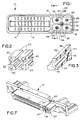
- electrical connector 10 contemplates a hybrid electrical connector that terminates both the conductors for data transmission lines and the conductors of high frequency transmission lines. More particularly, electrical connector 10, includes receptacle portion 12 having contact portions 14 of a plurality of terminals mounted therein exposed for engagement with appropriate contacts of a complementary mating male or plug-in connector.
- the left-hand portion or section of electrical connector 10 shown in Figure 1 forms a standard data connector. However, the right-hand portion or section of connector 10 provides a high frequency connector.
- connector 10 includes a dielectric housing 16 surrounded by a conductive shield 18 which spans substantially the entire length of the connector.
- An alternate embodiment of the housing is shown in Figure 7.
- Each insulator member 22 has a passage 24 for receiving signal contacts or terminals 26.
- Such passage 24 can be positioned within insulator 22 and with respect to ground member 20 in order to provide controlled impedance.
- Ground member 20 has a central circular portion 28 surrounding a passage 30 for receiving a ground contact or terminal 32.
- Ground member 20 is shaped to have spokes or webs 34 dividing the interior of the ground member into the quadrants.
- Figure 2 shows all four insulators 22 in a perspective depiction as they are located within ground member 20.
- Figure 3 shows a section through one of the insulators 22 to illustrate the configuration of passage 24 therethrough. It can be seen that the passage has an entry end 40 for receiving a contact of a complementary connector, a back wall 42, a through passage portion 44 and a shoulder 46.
- a signal contact generally designated 26 is shown positioned in passages 24.
- Each contact 26 includes a contact end 50 and a solder tail end 52.
- the contact end is disposed in passage 24 and the solder tail is provided for interconnection to a circuit trace on a printed circuit board as is known in the art.
- Contact end 50 is fabricated by a plurality of contact spring arms which are "crowned" for high hertzian interfacing with a receptacle-contact of the complementary connector.
- Each contact 26 is securely locked into position within its respective insulator 22 by means of a base portion 54 of the contact engaging back wall 42 of the insulator, and the base portion is provided with a locking barb 56 for snapping behind shoulder 46 of its insulator.
- solder tail portion 52 initially extends parallel to the axis of the contact end 50 so that the contacts can be loaded into insulators 22 in the direction of arrows "A" in Figure 5.
- base portions 54 of the contacts engage back walls 42 of the insulators, locking barbs 56 snap behind shoulders 44 of the insulators.
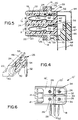
- Solder tails 52 then are bent downwardly as shown in Figures 4 and 5.
- Figure 5 also shows the positioning of shield 18 and how it surrounds housing 16 and common ground member 20.
- Shield 18 includes locking projections 59 which extend through openings in the dielectric housing 16, in the ground member 20 and in the back cover shielding member 64 to be engaged in openings similar to those (60) in Figure 7 in the dielectric housing 16′.
- the back cover shielding member 64 is made from a conductive material. These components are dimensioned so that the shield 18, ground member 20 and back cover 64 are mechanically and electrically secured to complete the ground circuit between them.
- Back cover 64 covers and shields the rear portion of the connector and the tail portions of the terminals.
- solder tail portions 52 are shown extending through passages in tail aligner 66.
- the solder tail portions 52 of the terminals 26, 32 have three different lengths.
- the longest solder tails are connected to the upper terminals 26 and extend through holes 68 in the tail aligner 66 (Fig. 8).
- the shortest solder tails are connected to the lower terminals 26 and extend through holes 70 in the tail aligner 66.
- the solder tail of ground terminal 32 has a length between those of the upper terminals and lower terminals and extend through hole 72 in the tail aligner 66.
- the tail aligner (Figs. 5 and 8) may include stepped portion 67.
- the stepped tail aligner 66 is dimensioned so as to balance the impedance of each line to a desired value.
- Figure 6 shows an alternate form of the invention in regard to the right-hand end or high frequency portion of electrical connector 10 described in relation to and in comparison to Figure 1.
- the connector is designated 10′ and like numerals have been applied to designate like components in comparison to the embodiment of Figure 3. Similar but not identical components are designated with a " ′ ".
- electrical connector 10′ also includes a common ground member, generally designated 20′ for surrounding ground contact 32 and electrically isolating contacts 26.
- ground member 20′ provides a common ground plane to control impedance, emissions of radiation and cross-talk between the contacts.
- the housing 16′ is shown isolated in Figure 7.
- the housing has passages for 24′ for receiving the signal contacts 26.
- the interior of the passages may be similar to the configuration of passages 24 (Fig. 3) in insulators 22.
- common ground member 20′ includes a central circular portion 28 (Fig.
- housing 16′ has internal passage means 76 of a shape corresponding to the cross-section of the spoked portion of common ground member 20′.
- this embodiment has the advantage of using main housing 16′ as the insulating means surrounding the signal contacts 26 which simplifies the assembly of the conductor. It should be understood that in many applications, only three signal contacts 26 would be provided, such as the "red”, “green” and “blue” signals to a video monitor.
- the passage in the fourth quadrant, for such applications, could be provided for other functions, such as a keying receptacle 80 (Fig. 10). Such passage could either be formed in the ground member 20′ or in the dielectric housing 16′.
- a plug (not shown) dimensioned to mate only with the keying receptacle is provided on the connector that mates with connector 10′.
- FIG 11 shows a further embodiment of the invention wherein an electrical connector 10 ⁇ (corresponding to connectors 10 and 10′) has the three high frequency signal contacts arranged in a vertically stacked array. Each contact is surrounded by a cylindrical insulator 82 which, in turn, is surrounded by a common conductive ground member 84 corresponding in function to the ground members 20 and 20′ in the embodiments of Figure 1 and 8, respectively. It can be seen that no separate ground contact (32 in Figs. 1 and 6) is incorporated in this embodiment.
- connectors 10, 10′ and 10 ⁇ will be utilized with similarly configured male connectors which are not described herein.
Landscapes
- Details Of Connecting Devices For Male And Female Coupling (AREA)
- Coupling Device And Connection With Printed Circuit (AREA)
Claims (9)
- Connecteur électrique blindé (10, 10′) globalement rectangulaire, pour accouplement avec un autre connecteur électrique suivant un axe d'accouplement (A), ledit connecteur blindé comprenant un boîtier diélectrique (16, 16′) ayant une face d'accouplement globalement perpendiculaire audit axe d'accouplement et une face opposée à ladite face d'accouplement, un élément de blindage conducteur extérieur (18) entourant globalement une région dudit boîtier (10, 10′) pour accouplement avec ledit autre connecteur électrique, une première partie (12) dudit boîtier portant plusieurs premières bornes (14) en un premier groupement donné pour interconnexion avec plusieurs premières bornes dudit autre connecteur électrique, et une seconde partie dudit boîtier (10, 10′) portant plusieurs secondes bornes (26) en un second groupement donné pour interconnexion avec plusieurs secondes bornes dudit autre connecteur électrique ;
caractérisé :
en ce qu'un élément de mise à la masse conducteur commun (20, 20′) est monté sur ladite seconde partie dudit boîtier (10, 10′) avec des parties (28, 34) de l'élément de mise à la masse (20, 20′) disposées entre les secondes bornes (26) ; et
en ce qu'un moyen d'accès (76) adjacent auxdites secondes parties dudit boîtier (10, 10′) s'étend à travers une surface extérieure dudit boîtier pour permettre l'introduction dudit élément de mise à la masse (20, 20′) dans ledit boîtier. - Connecteur électrique selon la revendication 1, dans lequel ledit élément de mise à la masse commun (20) comprend une partie (28) comportant un moyen formant conduit (30) la traversant pour recevoir et entourer une borne de masse (32).
- Connecteur électrique selon la revendication 2, dans lequel ladite partie de l'élément de mise à la masse commun (20, 20′) pour recevoir la borne de masse (32) est disposée au centre de l'élément de mise à la masse commun (20, 20′).
- Connecteur électrique selon la revendication 3, dans lequel ledit élément de mise à la masse commun (20) comprend plusieurs parties en forme de rayons (34) rayonnant vers l'extérieur de la borne de masse et disposées entre certaines des secondes bornes (26) adjacentes respectives.
- Connecteur électrique selon la revendication 4, dans lequel ledit élément de mise à la masse commun (20) possède des parties périphériques (34) rejoignant les extrémités distales des parties en forme de rayons, ce par quoi l'élément de mise à la masse commun entoure chacune des secondes bornes.
- Connecteur électrique selon la revendication 1, dans lequel ledit boîtier (16) est un élément moulé d'une seule pièce, ledit élément de mise à la masse (20) est un élément d'une seule pièce et ledit moyen d'accès (76) est une fente qui permet l'introduction dudit élément de mise à la masse d'une seule pièce suivant un axe globalement parallèle audit axe d'accouplement, à travers l'une desdites faces et dans ledit boîtier.
- Connecteur électrique selon la revendication 6, dans lequel ledit élément de mise à la masse commun (20) comprend une partie comportant un moyen formant conduit (30) la traversant pour recevoir et entourer une borne de masse (32).
- Connecteur électrique selon la revendication 6, dans lequel ledit élément de blindage conducteur extérieur (18) est relié mécaniquement et électriquement audit élément conducteur de mise à la masse (20).
- Connecteur électrique selon la revendication 8, comprenant en outre un moyen d'agrafage (59) pour fixer mécaniquement et électriquement l'élément conducteur de mise à la masse à l'élément de blindage extérieur (18).
Priority Applications (1)
| Application Number | Priority Date | Filing Date | Title |
|---|---|---|---|
| EP95101101A EP0654867B1 (fr) | 1991-06-06 | 1992-06-03 | Assemblage de connecteur électrique |
Applications Claiming Priority (2)
| Application Number | Priority Date | Filing Date | Title |
|---|---|---|---|
| US07/711,231 US5102353A (en) | 1991-06-06 | 1991-06-06 | Electrical connectors |
| US711231 | 1991-06-06 |
Related Child Applications (1)
| Application Number | Title | Priority Date | Filing Date |
|---|---|---|---|
| EP95101101.4 Division-Into | 1995-01-27 |
Publications (2)
| Publication Number | Publication Date |
|---|---|
| EP0517180A1 EP0517180A1 (fr) | 1992-12-09 |
| EP0517180B1 true EP0517180B1 (fr) | 1995-11-15 |
Family
ID=24857251
Family Applications (2)
| Application Number | Title | Priority Date | Filing Date |
|---|---|---|---|
| EP95101101A Expired - Lifetime EP0654867B1 (fr) | 1991-06-06 | 1992-06-03 | Assemblage de connecteur électrique |
| EP92109370A Expired - Lifetime EP0517180B1 (fr) | 1991-06-06 | 1992-06-03 | Connecteurs électriques |
Family Applications Before (1)
| Application Number | Title | Priority Date | Filing Date |
|---|---|---|---|
| EP95101101A Expired - Lifetime EP0654867B1 (fr) | 1991-06-06 | 1992-06-03 | Assemblage de connecteur électrique |
Country Status (7)
| Country | Link |
|---|---|
| US (2) | US5102353A (fr) |
| EP (2) | EP0654867B1 (fr) |
| JP (1) | JP2538823B2 (fr) |
| KR (1) | KR950007425B1 (fr) |
| DE (2) | DE69206048T2 (fr) |
| SG (1) | SG46347A1 (fr) |
| TW (1) | TW198143B (fr) |
Families Citing this family (43)
| Publication number | Priority date | Publication date | Assignee | Title |
|---|---|---|---|---|
| JP3298920B2 (ja) * | 1992-04-03 | 2002-07-08 | タイコエレクトロニクスアンプ株式会社 | シールド型電気コネクタ |
| EP0590797B1 (fr) * | 1992-09-28 | 1998-12-09 | The Whitaker Corporation | Connecteur électrique monté sur plaquette de circuits |
| US5310364A (en) * | 1992-11-03 | 1994-05-10 | Burndy Corporation | Grounding block |
| DE4309155C2 (de) * | 1993-03-22 | 1995-06-01 | Itt Cannon Gmbh | Steckverbinder, insbesondere für ein Mobiltelefon |
| SG43073A1 (en) * | 1993-05-14 | 1997-10-17 | Molex Inc | Shielded electrical connector assembly |
| NL9300971A (nl) * | 1993-06-04 | 1995-01-02 | Framatome Connectors Belgium | Connectorsamenstel voor printkaarten. |
| US5304069A (en) * | 1993-07-22 | 1994-04-19 | Molex Incorporated | Grounding electrical connectors |
| US5387114A (en) * | 1993-07-22 | 1995-02-07 | Molex Incorporated | Electrical connector with means for altering circuit characteristics |
| US5344327A (en) * | 1993-07-22 | 1994-09-06 | Molex Incorporated | Electrical connectors |
| US5356300A (en) * | 1993-09-16 | 1994-10-18 | The Whitaker Corporation | Blind mating guides with ground contacts |
| US5547385A (en) * | 1994-05-27 | 1996-08-20 | The Whitaker Corporation | Blind mating guides on backwards compatible connector |
| EP0693795B1 (fr) * | 1994-07-22 | 1999-03-17 | Berg Electronics Manufacturing B.V. | Connecteur sélectivement métallisé avec au moins un contact coaxial ou biaxial |
| USD400858S (en) * | 1995-05-09 | 1998-11-10 | Sony Corporation | Connector |
| US5558542A (en) * | 1995-09-08 | 1996-09-24 | Molex Incorporated | Electrical connector with improved terminal-receiving passage means |
| US5658155A (en) * | 1996-01-11 | 1997-08-19 | Molex Incorporated | Electrical connector with terminal tail aligning device |
| US5876248A (en) * | 1997-01-14 | 1999-03-02 | Molex Incorporated | Matable electrical connectors having signal and power terminals |
| FR2758912B1 (fr) * | 1997-01-30 | 1999-04-02 | Framatome Connectors Int | Ensemble de connexion electrique a blindage |
| FR2768862B1 (fr) | 1997-09-22 | 1999-12-24 | Infra Sa | Prise de courant faible a capuchon arriere organisateur |
| US6000955A (en) * | 1997-12-10 | 1999-12-14 | Gabriel Technologies, Inc. | Multiple terminal edge connector |
| US6328601B1 (en) | 1998-01-15 | 2001-12-11 | The Siemon Company | Enhanced performance telecommunications connector |
| US6358091B1 (en) | 1998-01-15 | 2002-03-19 | The Siemon Company | Telecommunications connector having multi-pair modularity |
| US6780054B2 (en) | 1998-01-15 | 2004-08-24 | The Siemon Company | Shielded outlet having contact tails shield |
| SG94711A1 (en) | 1998-09-15 | 2003-03-18 | Molex Inc | Electrical connector for mounting on a printed circuit board and including a terminal tail aligner |
| SG101926A1 (en) * | 1999-11-12 | 2004-02-27 | Molex Inc | Power connector |
| JP2002280121A (ja) * | 2001-03-19 | 2002-09-27 | Jst Mfg Co Ltd | 電気コネクタ、および伝送路 |
| GB0116696D0 (en) * | 2001-07-09 | 2001-08-29 | Patchen Ltd | Device cover patent |
| TW556981U (en) * | 2002-09-25 | 2003-10-01 | Hon Hai Prec Ind Co Ltd | Electrical connector |
| EP1422791A1 (fr) * | 2002-11-21 | 2004-05-26 | Tyco Electronics AMP GmbH | Agencement de connecteurs |
| TW572456U (en) * | 2003-05-07 | 2004-01-11 | Hon Hai Prec Ind Co Ltd | Electrical connector |
| DE102009019626B3 (de) * | 2009-04-30 | 2011-03-03 | Tyco Electronics Amp Gmbh | Elektrischer Verbinder mit Impedanzkorrekturelement und Verfahren zu seiner Herstellung |
| US7824229B1 (en) * | 2009-07-10 | 2010-11-02 | Cheng Uei Precision Industry Co., Ltd. | Audio plug connector |
| DE102011005301B4 (de) * | 2011-03-09 | 2018-01-11 | Te Connectivity Germany Gmbh | Elektrischer Steckverbinder |
| US9070998B2 (en) * | 2012-07-27 | 2015-06-30 | Amphenol Corporation | High speed electrical contact assembly |
| US10078612B2 (en) * | 2014-07-28 | 2018-09-18 | Intel Corporation | Mode selective balanced encoded interconnect |
| JP6281481B2 (ja) * | 2014-12-17 | 2018-02-21 | 株式会社オートネットワーク技術研究所 | コネクタ及び電線ユニット |
| CN105846219A (zh) * | 2016-04-25 | 2016-08-10 | 安费诺电子装配(厦门)有限公司 | 高速数据传输连接器模组 |
| CN207925721U (zh) * | 2018-01-30 | 2018-09-28 | 富誉电子科技(淮安)有限公司 | 电源连接器 |
| WO2020085398A1 (fr) | 2018-10-26 | 2020-04-30 | 第一精工株式会社 | Dispositif de connecteur coaxial |
| JP7187975B2 (ja) | 2018-10-26 | 2022-12-13 | I-Pex株式会社 | 同軸コネクタ装置 |
| JP7273525B2 (ja) * | 2019-01-29 | 2023-05-15 | モレックス エルエルシー | コネクタ及びコネクタ組立体 |
| KR20230038587A (ko) * | 2020-08-04 | 2023-03-20 | 몰렉스 엘엘씨 | 커넥터 및 커넥터 쌍 |
| DE102021204799A1 (de) * | 2021-05-11 | 2022-11-17 | Robert Bosch Gesellschaft mit beschränkter Haftung | Elektronische Baugruppe |
| JP2023035715A (ja) * | 2021-09-01 | 2023-03-13 | 日本航空電子工業株式会社 | コネクタ |
Family Cites Families (17)
| Publication number | Priority date | Publication date | Assignee | Title |
|---|---|---|---|---|
| FR542481A (fr) * | 1921-10-11 | 1922-08-12 | Raccord pour courant électrique à trois conducteurs | |
| BE530035A (fr) * | 1953-07-03 | |||
| US4340265A (en) * | 1980-05-02 | 1982-07-20 | Automatic Connector, Inc. | Multi-coaxial/power pin connector assembly having integral ground |
| US4571014A (en) * | 1984-05-02 | 1986-02-18 | At&T Bell Laboratories | High frequency modular connector |
| DE3511344A1 (de) * | 1985-03-28 | 1986-10-02 | Siemens AG, 1000 Berlin und 8000 München | Steckverbinder fuer rueckwandverdrahtungen |
| US4702707A (en) * | 1986-08-15 | 1987-10-27 | Amp Incorporated | Power contact having removable mating components |
| JPH02501870A (ja) * | 1986-10-03 | 1990-06-21 | ミネソタ マイニング アンド マニユフアクチユアリング カンパニー | 同軸ケーブル用のシールドされ且つ接地されたコネクタシステム |
| US4846727A (en) * | 1988-04-11 | 1989-07-11 | Amp Incorporated | Reference conductor for improving signal integrity in electrical connectors |
| JPH01296576A (ja) * | 1988-05-25 | 1989-11-29 | Nippon Ee M P Kk | 電気コネクター |
| US4846711A (en) * | 1988-08-09 | 1989-07-11 | Amp Incorporated | Coaxial connector in a housing block |
| US4941833A (en) * | 1988-10-06 | 1990-07-17 | Burndy Corporation | Controlled impedance plug and receptacle |
| US5018985A (en) * | 1989-08-21 | 1991-05-28 | Itt Corporation | Connector with modular terminal devices |
| US5060373A (en) * | 1989-08-22 | 1991-10-29 | The Phoenix Company Of Chicago, Inc. | Methods for making coaxial connectors |
| US5006236A (en) * | 1989-09-25 | 1991-04-09 | Hallco Fabricators, Inc. | Contaminant entrained flow separating apparatus |
| GB8928777D0 (en) * | 1989-12-20 | 1990-02-28 | Amp Holland | Sheilded backplane connector |
| US5046952A (en) * | 1990-06-08 | 1991-09-10 | Amp Incorporated | Right angle connector for mounting to printed circuit board |
| JP2739608B2 (ja) * | 1990-11-15 | 1998-04-15 | 日本エー・エム・ピー株式会社 | 信号伝送用マルチコンタクト型コネクタ |
-
1991
- 1991-06-06 US US07/711,231 patent/US5102353A/en not_active Ceased
-
1992
- 1992-04-06 TW TW081102609A patent/TW198143B/zh active
- 1992-06-03 DE DE69206048T patent/DE69206048T2/de not_active Expired - Fee Related
- 1992-06-03 DE DE69227597T patent/DE69227597T2/de not_active Expired - Fee Related
- 1992-06-03 JP JP4168518A patent/JP2538823B2/ja not_active Expired - Fee Related
- 1992-06-03 EP EP95101101A patent/EP0654867B1/fr not_active Expired - Lifetime
- 1992-06-03 EP EP92109370A patent/EP0517180B1/fr not_active Expired - Lifetime
- 1992-06-03 SG SG1996003263A patent/SG46347A1/en unknown
- 1992-06-05 KR KR1019920009789A patent/KR950007425B1/ko not_active IP Right Cessation
-
1993
- 1993-10-28 US US08/144,863 patent/USRE35159E/en not_active Expired - Lifetime
Also Published As
| Publication number | Publication date |
|---|---|
| DE69206048T2 (de) | 1996-04-25 |
| EP0517180A1 (fr) | 1992-12-09 |
| JPH0652936A (ja) | 1994-02-25 |
| SG46347A1 (en) | 1998-02-20 |
| DE69206048D1 (de) | 1995-12-21 |
| TW198143B (fr) | 1993-01-11 |
| JP2538823B2 (ja) | 1996-10-02 |
| EP0654867B1 (fr) | 1998-11-11 |
| EP0654867A1 (fr) | 1995-05-24 |
| USRE35159E (en) | 1996-02-20 |
| US5102353A (en) | 1992-04-07 |
| DE69227597T2 (de) | 1999-07-15 |
| DE69227597D1 (de) | 1998-12-17 |
| KR930001521A (ko) | 1993-01-16 |
| KR950007425B1 (ko) | 1995-07-10 |
Similar Documents
| Publication | Publication Date | Title |
|---|---|---|
| EP0517180B1 (fr) | Connecteurs électriques | |
| KR0129984Y1 (ko) | 전기 커넥터 | |
| EP0635905B1 (fr) | Connecteur électrique de mise à la terre | |
| EP0523491B1 (fr) | Connecteur électrique modulaire | |
| EP0405454B1 (fr) | Elément coaxial de contact | |
| US6790089B2 (en) | Cable assembly | |
| US6835092B2 (en) | Stacked electrical connector assembly with enhanced grounding arrangement | |
| US6582244B2 (en) | Connector interface and retention system for high-density connector | |
| US6848950B2 (en) | Multi-interface power contact and electrical connector including same | |
| US6368121B1 (en) | Plug connector, jack connector and connector assembly | |
| US7004793B2 (en) | Low inductance shielded connector | |
| US7083468B2 (en) | Stacked electrical connector assembly | |
| EP0836249A1 (fr) | Enveloppe électrique de mise à la terre | |
| US6638079B1 (en) | Customizable electrical connector | |
| CA2144704A1 (fr) | Connecteur combine | |
| KR20020020783A (ko) | 임피던스가 조정되는 커넥터 | |
| JPS6391977A (ja) | プラグ/リセプタクル式のコネクタ | |
| US7052329B2 (en) | Electrical connector with an internal modem | |
| US6503101B1 (en) | Electrical connector having grounding path | |
| EP0624928B1 (fr) | Ensemble connecteur électrique blindé | |
| US6783398B2 (en) | Shielded modular jack assembly for ethernet applications | |
| WO1987007441A1 (fr) | Connecteur electrique blinde | |
| US6736680B2 (en) | Modular jack assembly for ethernet applications | |
| US6106334A (en) | Shielded cable connector | |
| US4553800A (en) | Low profile modular plug |
Legal Events
| Date | Code | Title | Description |
|---|---|---|---|
| PUAI | Public reference made under article 153(3) epc to a published international application that has entered the european phase |
Free format text: ORIGINAL CODE: 0009012 |
|
| AK | Designated contracting states |
Kind code of ref document: A1 Designated state(s): DE FR GB IT |
|
| 17P | Request for examination filed |
Effective date: 19930602 |
|
| 17Q | First examination report despatched |
Effective date: 19940525 |
|
| ITF | It: translation for a ep patent filed | ||
| GRAA | (expected) grant |
Free format text: ORIGINAL CODE: 0009210 |
|
| AK | Designated contracting states |
Kind code of ref document: B1 Designated state(s): DE FR GB IT |
|
| XX | Miscellaneous (additional remarks) |
Free format text: TEILANMELDUNG 95101101.4 EINGEREICHT AM 27/01/95. |
|
| REF | Corresponds to: |
Ref document number: 69206048 Country of ref document: DE Date of ref document: 19951221 |
|
| ET | Fr: translation filed | ||
| PLBE | No opposition filed within time limit |
Free format text: ORIGINAL CODE: 0009261 |
|
| STAA | Information on the status of an ep patent application or granted ep patent |
Free format text: STATUS: NO OPPOSITION FILED WITHIN TIME LIMIT |
|
| 26N | No opposition filed | ||
| REG | Reference to a national code |
Ref country code: GB Ref legal event code: IF02 |
|
| PGFP | Annual fee paid to national office [announced via postgrant information from national office to epo] |
Ref country code: GB Payment date: 20050506 Year of fee payment: 14 |
|
| PGFP | Annual fee paid to national office [announced via postgrant information from national office to epo] |
Ref country code: FR Payment date: 20050602 Year of fee payment: 14 |
|
| PGFP | Annual fee paid to national office [announced via postgrant information from national office to epo] |
Ref country code: DE Payment date: 20050630 Year of fee payment: 14 |
|
| PG25 | Lapsed in a contracting state [announced via postgrant information from national office to epo] |
Ref country code: GB Free format text: LAPSE BECAUSE OF NON-PAYMENT OF DUE FEES Effective date: 20060603 |
|
| PGFP | Annual fee paid to national office [announced via postgrant information from national office to epo] |
Ref country code: IT Payment date: 20060630 Year of fee payment: 15 |
|
| PG25 | Lapsed in a contracting state [announced via postgrant information from national office to epo] |
Ref country code: DE Free format text: LAPSE BECAUSE OF NON-PAYMENT OF DUE FEES Effective date: 20070103 |
|
| GBPC | Gb: european patent ceased through non-payment of renewal fee |
Effective date: 20060603 |
|
| REG | Reference to a national code |
Ref country code: FR Ref legal event code: ST Effective date: 20070228 |
|
| PG25 | Lapsed in a contracting state [announced via postgrant information from national office to epo] |
Ref country code: FR Free format text: LAPSE BECAUSE OF NON-PAYMENT OF DUE FEES Effective date: 20060630 |
|
| PG25 | Lapsed in a contracting state [announced via postgrant information from national office to epo] |
Ref country code: IT Free format text: LAPSE BECAUSE OF NON-PAYMENT OF DUE FEES Effective date: 20070603 |