EP0517130B1 - Toe guard for an elevator - Google Patents
Toe guard for an elevator Download PDFInfo
- Publication number
- EP0517130B1 EP0517130B1 EP92109180A EP92109180A EP0517130B1 EP 0517130 B1 EP0517130 B1 EP 0517130B1 EP 92109180 A EP92109180 A EP 92109180A EP 92109180 A EP92109180 A EP 92109180A EP 0517130 B1 EP0517130 B1 EP 0517130B1
- Authority
- EP
- European Patent Office
- Prior art keywords
- toe guard
- air
- elevator
- car
- toe
- Prior art date
- Legal status (The legal status is an assumption and is not a legal conclusion. Google has not performed a legal analysis and makes no representation as to the accuracy of the status listed.)
- Expired - Lifetime
Links
Images

Classifications
-
- B—PERFORMING OPERATIONS; TRANSPORTING
- B66—HOISTING; LIFTING; HAULING
- B66B—ELEVATORS; ESCALATORS OR MOVING WALKWAYS
- B66B13/00—Doors, gates, or other apparatus controlling access to, or exit from, cages or lift well landings
- B66B13/24—Safety devices in passenger lifts, not otherwise provided for, for preventing trapping of passengers
- B66B13/28—Safety devices in passenger lifts, not otherwise provided for, for preventing trapping of passengers between car or cage and wells
- B66B13/285—Toe guards or apron devices
-
- B—PERFORMING OPERATIONS; TRANSPORTING
- B66—HOISTING; LIFTING; HAULING
- B66B—ELEVATORS; ESCALATORS OR MOVING WALKWAYS
- B66B11/00—Main component parts of lifts in, or associated with, buildings or other structures
- B66B11/02—Cages, i.e. cars
- B66B11/0226—Constructional features, e.g. walls assembly, decorative panels, comfort equipment, thermal or sound insulation
Landscapes
- Engineering & Computer Science (AREA)
- Civil Engineering (AREA)
- Mechanical Engineering (AREA)
- Structural Engineering (AREA)
- Cage And Drive Apparatuses For Elevators (AREA)
Description
- The present invention concerns a toe guard for an elevator, known per se from either of US-A-5018602, GB-A-1481619 and EP-A-418511.
- An elevator car is provided with a toe guard, which is a downward extension of the front wall, i.e. the wall containing the door. The toe guard consists of a plate-like element whose lower part diverges slightly inwards into the elevator shaft from the direction of the front wall, and a supporting structure designed to increase the rigidity of the toe guard. The function of the toe guard is to ensure safe exit of passengers from the elevator car in case it stops between floors e.g. due to a power failure.
- A problem with the conventional toe guard is that, especially in the case of fast elevators, when the elevator car is travelling downwards, the toe guard with its inclined shape acts as a booster which strengthens the air current in the space between the front wall of the elevator car and the shaft wall. The velocity of this air current increases faster than that of the elevator car and generates a disturbing noise that penetrates into the passenger space of the elevator car. A low noise level in the passenger space is considered to be one of the most important aspects of passenger comfort. To reduce the noise level, fast elevators are often provided with sound insulations, but it is relatively difficult to damp the noise generated by the air current between the shaft wall and the front wall of the car. This is due to the structure of the car doors, e.g. because the doors are not completely air-tight.
- The object of the present invention is to achieve a new type of toe guard designed to solve the problem described above. The toe guard of the invention is characterized by what is presented in
claim 1. The features characteristic of other embodiments of the invention are presented in the other claims. - As compared to previously known techniques, the invention provides the following advantages:
- The air current directed by the toe guard into the gap between the elevator car front wall and the shaft wall is reduced, thereby reducing the noise generated by the current.
- The pressure difference across the toe guard is reduced, reducing its tendency to vibrate.
- Since less air is forced into the gap between the car and the shaft wall opposite to the car door, the pressure in the gap is lower and therefore the force applied to the elevator car by this pressure is reduced, thus also reducing the offset-type load on the guides.
- Although the primary function of the invention is to reduce the pressure of the air dammed in below the toe guard during descent which increases the air current between the car front wall and the shaft wall, the invention also reduces the air current during ascent because the suction at the trailing edge is reduced.
- The invention is described in more detail by referring to the attached drawings, in which
- Fig. 1 presents a previously known toe guard
- Fig. 2 presents the toe guard of the invention in lateral view,
- Fig. 3 presents the same toe guard as seen from the shaft, and
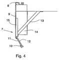
- Fig. 4 presents a more detailed view of the toe guard of the invention.
- The
conventional toe guard 1 shown in Fig. 1 is implemented as a downward extension of the front wall of the elevator car and forms between itslower part 2 and the shaft wall 3 a cavity which opens in the downward direction. During down-travel of the elevator car, this cavity compresses the air from width A into width B. The packing of the air current is represented by arrows. Since the air flows from a larger cross-sectional area into a narrower area, the velocity of the flow in the narrower cross-sectional area must be higher in order to maintain the same volume flow. The high flow rate generates a disturbing noise which reaches the passenger space of the elevator. The amplitude of the noise increases clearly faster than the flow rate, so the velocity of the air current is a critical factor affecting the travelling comfort provided by an elevator car. When the elevator is moving upwards, the cavity formed by the toe guard creates a suction increasing the air flow between theshaft wall 3 and the front wall of the elevator car. The increase in the flow is smaller than during descent. - Fig. 2 is a simplified illustration of the
toe guard 4 of the invention. Thelower part 5 of the toe guard is of a construction penetrable to air. In this case, part of the air entering the cavity A flows through thelower part 5, thus reducing the volume flow through width B. To prevent the air from being packed below the car, the toe guard is provided with a V-shaped air guide which quickly directs the air to the sides of the car. The air flow is represented by arrows. Correspondingly, when the elevator is moving upwards, the air flows in the opposite direction. Fig. 3 presents the same toe guard as seen from the shaft. The flow of the air passing through thelower part 5 of toe guard to theair guide 6 and further to the sides of the car is represented by arrows. - An advantageous toe gard shown in Fig. 4 consists of a separate plate parts and supporting elements suitably connected. Fig. 4 shows a possible implementation in lateral view. The
toe guard 7 consists of aplate part 9 extending downwards from thethreshold 8 of the elevator car, and aframe 10 provided in its lower part. In this case theplate part 9 and theframe 10 are made of one piece. Theframe 10 has been produced by bending the edges of the common blank of the parts and making cut-outs in it as appropriate. Theframe 10 accommodates anetwork 11, which is held in place by means of amounting element 12 provided with cut-outs corresponding to the frame. The toe guard is fixed to the lower part of the elevator car by means of abracing structure 13 designed to receive any horizontal forces that may be applied to the toe guard. On that side of the toe guard which faces the elevator shaft there is a plough-type flow guide 14 which, being of a more streamlined shape than the bottom of the elevator car, directs the air flow to the sides of the car, thus reducing the pressure of the air congested under the car. Providing the toe guard plate withreinforcements 15 allows a relatively thin plate to be used. The parts can be joined together in any suitable manner, which is not described here. In addition to its lower part, the toe guard may be provided with further cut-outs to distribute the air pressure between the opposite sides of the plate. - It is obvious to a person skilled in the art that different embodiments of the invention are not restricted to the examples described above, but that they may instead be varied within the scope of the following claims. For example, instead of a network it is possible to use a grating, or the toe guard plate can be provided with perforations, in which case no separate part penetrable to air will be needed. Similarly, the air flow can be directed to the sides of the car e.g. by means of vanes instead of a plough-type structure, or by appropriately shaping the lower part of the car. The elements directing the air flow to the sides, whether plough-type or some other type of elements, can be integrated with the reinforcements or bracing elements of the toe guard.
Claims (6)
- Toe guard for an elevator, which is a downward extension of the front wall of the elevator car, characterized in that at least a part of the toe guard (4,7) consists of a structure (5,11) penetrable to air flow.
- Toe guard according to claim 1, characterized in that the toe guard (4,7) comprises at least one element (6,14) designed to guide the air flow.
- Toe guard according to any one of the previous claims, characterized in that the part (5,11) penetrable to air is the lower part of the toe guard (4,7).
- Toe guard according to any one of the previous claims, characterized in that the part penetrable to air is a network (11) or a grating.
- Toe guard according to any one of the previous claims, characterized in that the toe guard (4,7) comprises a front plate (9) having in its lower part a frame (10) accommodating the part (11) penetrable to air, and that the toe guard is held steady by means of a bracing structure (13) securing it to the bottom part of the elevator car and that the toe guard is provided with a plough-type air flow guide (14).
- Toe guard according to any one of the previous claims, characterized in that the air flow guide (14) also acts as a reinforcement and bracing structure of the toe guard (4,7).
Applications Claiming Priority (2)
| Application Number | Priority Date | Filing Date | Title |
|---|---|---|---|
| FI912719A FI87642C (en) | 1991-06-06 | 1991-06-06 | Toe protection by a lift |
| FI912719 | 1991-06-06 |
Publications (2)
| Publication Number | Publication Date |
|---|---|
| EP0517130A1 EP0517130A1 (en) | 1992-12-09 |
| EP0517130B1 true EP0517130B1 (en) | 1995-08-23 |
Family
ID=8532651
Family Applications (1)
| Application Number | Title | Priority Date | Filing Date |
|---|---|---|---|
| EP92109180A Expired - Lifetime EP0517130B1 (en) | 1991-06-06 | 1992-06-01 | Toe guard for an elevator |
Country Status (7)
| Country | Link |
|---|---|
| US (1) | US5251726A (en) |
| EP (1) | EP0517130B1 (en) |
| JP (1) | JP3014863B2 (en) |
| AU (1) | AU650742B2 (en) |
| CA (1) | CA2069581C (en) |
| DE (1) | DE69204216T2 (en) |
| FI (1) | FI87642C (en) |
Families Citing this family (11)
| Publication number | Priority date | Publication date | Assignee | Title |
|---|---|---|---|---|
| US6095288A (en) * | 1999-04-22 | 2000-08-01 | Otis Elevator Company | Pit-less elevator |
| DE50212434D1 (en) * | 2002-02-27 | 2008-08-14 | Thyssenkrupp Aufzugswerke Gmbh | Prevent the opening of an elevator door |
| JP2009113886A (en) * | 2007-11-02 | 2009-05-28 | Toshiba Elevator Co Ltd | Protective plate device of elevator |
| JP5653231B2 (en) * | 2011-01-19 | 2015-01-14 | 東芝エレベータ株式会社 | Elevator equipment |
| EP2762435B1 (en) * | 2013-02-04 | 2015-07-15 | Kone Corporation | Elevator |
| EP3031766A1 (en) * | 2014-12-11 | 2016-06-15 | KONE Corporation | Elevator car |
| EP3031767B1 (en) | 2014-12-12 | 2021-08-25 | Kone Corporation | Elevator door sill |
| ES2911757T3 (en) * | 2014-12-23 | 2022-05-20 | Otis Elevator Co | Elevator system with ventilation system |
| US10246300B2 (en) * | 2015-06-30 | 2019-04-02 | Otis Elevator Company | Elevator virtual aerodynamic shroud |
| CN107032210B (en) * | 2015-07-13 | 2020-12-01 | 奥的斯电梯公司 | Elevator system muffler assembly and method |
| CN117203148A (en) * | 2021-04-30 | 2023-12-08 | 三菱电机株式会社 | Elevator with a motor |
Family Cites Families (7)
| Publication number | Priority date | Publication date | Assignee | Title |
|---|---|---|---|---|
| JPS5088754A (en) * | 1973-12-14 | 1975-07-16 | ||
| US3945468A (en) * | 1974-12-11 | 1976-03-23 | Hitachi, Ltd. | Sound preventive device for use in elevator |
| JPS5220545A (en) * | 1975-08-08 | 1977-02-16 | Hitachi Ltd | Elevator cage |
| JPH02231386A (en) * | 1989-03-01 | 1990-09-13 | Mitsubishi Electric Corp | Cage for high speed elevator |
| ATE94848T1 (en) * | 1989-09-22 | 1993-10-15 | Inventio Ag | DEVICE FOR VENTILATION OF HIGH-SPEED ELEVATOR CARS. |
| JPH03158377A (en) * | 1989-11-13 | 1991-07-08 | Mitsubishi Electric Corp | Speed reducer for elevator |
| US5018602A (en) * | 1990-03-21 | 1991-05-28 | Otis Elevator Company | Reduction of noise and vibration in an elevator car by selectively reducing air turbulence |
-
1991
- 1991-06-06 FI FI912719A patent/FI87642C/en not_active IP Right Cessation
-
1992
- 1992-05-08 AU AU16103/92A patent/AU650742B2/en not_active Ceased
- 1992-05-26 CA CA002069581A patent/CA2069581C/en not_active Expired - Fee Related
- 1992-06-01 DE DE69204216T patent/DE69204216T2/en not_active Expired - Fee Related
- 1992-06-01 EP EP92109180A patent/EP0517130B1/en not_active Expired - Lifetime
- 1992-06-02 US US07/892,314 patent/US5251726A/en not_active Expired - Fee Related
- 1992-06-05 JP JP4169962A patent/JP3014863B2/en not_active Expired - Lifetime
Also Published As
| Publication number | Publication date |
|---|---|
| FI87642B (en) | 1992-10-30 |
| AU650742B2 (en) | 1994-06-30 |
| DE69204216T2 (en) | 1996-04-04 |
| US5251726A (en) | 1993-10-12 |
| JPH05178567A (en) | 1993-07-20 |
| DE69204216D1 (en) | 1995-09-28 |
| CA2069581A1 (en) | 1992-12-07 |
| FI87642C (en) | 1993-02-10 |
| FI912719A0 (en) | 1991-06-06 |
| AU1610392A (en) | 1992-12-10 |
| JP3014863B2 (en) | 2000-02-28 |
| EP0517130A1 (en) | 1992-12-09 |
| CA2069581C (en) | 1996-10-29 |
Similar Documents
| Publication | Publication Date | Title |
|---|---|---|
| EP0517130B1 (en) | Toe guard for an elevator | |
| US5220979A (en) | Elevator | |
| EP0389873B1 (en) | Window regulator apparatus | |
| US5018602A (en) | Reduction of noise and vibration in an elevator car by selectively reducing air turbulence | |
| EP0661229A1 (en) | Floorplate frame for a people moving device | |
| US4731951A (en) | Vehicle door structure | |
| FI98363C (en) | Lift car threshold system | |
| EP1106408A1 (en) | Center channel fixation for a door in vehicle | |
| EP3822214A1 (en) | Sound absorbing panels for elevator | |
| EP0938445A1 (en) | Elevator cab | |
| US4793441A (en) | Elevator car system with three guide rails | |
| JP2898815B2 (en) | Elevator cage air conditioner | |
| JP2896260B2 (en) | Elevator door equipment | |
| US7147087B2 (en) | Elevator with duct for tail cord | |
| JPS6116295Y2 (en) | ||
| JP2001106460A (en) | Elevator car | |
| WO2021220436A1 (en) | Sub-weight for balance weight, and elevator system in which same is used | |
| JPS5837235B2 (en) | elevator | |
| JP2003048676A (en) | Elevator car | |
| JP6268317B2 (en) | Counterweight and elevator equipment | |
| EP0146318A2 (en) | Vehicle door structure | |
| JPH0925078A (en) | Car of elevator | |
| KR0115040Y1 (en) | Noise flow in defector of elevator car | |
| JPH0111657Y2 (en) | ||
| KR20000052033A (en) | Prevention of noise structure in elevator |
Legal Events
| Date | Code | Title | Description |
|---|---|---|---|
| PUAI | Public reference made under article 153(3) epc to a published international application that has entered the european phase |
Free format text: ORIGINAL CODE: 0009012 |
|
| AK | Designated contracting states |
Kind code of ref document: A1 Designated state(s): DE FR GB |
|
| 17P | Request for examination filed |
Effective date: 19930527 |
|
| 17Q | First examination report despatched |
Effective date: 19950126 |
|
| GRAA | (expected) grant |
Free format text: ORIGINAL CODE: 0009210 |
|
| AK | Designated contracting states |
Kind code of ref document: B1 Designated state(s): DE FR GB |
|
| REF | Corresponds to: |
Ref document number: 69204216 Country of ref document: DE Date of ref document: 19950928 |
|
| ET | Fr: translation filed | ||
| PLBE | No opposition filed within time limit |
Free format text: ORIGINAL CODE: 0009261 |
|
| STAA | Information on the status of an ep patent application or granted ep patent |
Free format text: STATUS: NO OPPOSITION FILED WITHIN TIME LIMIT |
|
| 26N | No opposition filed | ||
| REG | Reference to a national code |
Ref country code: GB Ref legal event code: IF02 |
|
| REG | Reference to a national code |
Ref country code: GB Ref legal event code: 732E |
|
| REG | Reference to a national code |
Ref country code: FR Ref legal event code: TP Ref country code: FR Ref legal event code: CA |
|
| PGFP | Annual fee paid to national office [announced via postgrant information from national office to epo] |
Ref country code: FR Payment date: 20040513 Year of fee payment: 13 |
|
| PGFP | Annual fee paid to national office [announced via postgrant information from national office to epo] |
Ref country code: GB Payment date: 20040517 Year of fee payment: 13 |
|
| PGFP | Annual fee paid to national office [announced via postgrant information from national office to epo] |
Ref country code: DE Payment date: 20040520 Year of fee payment: 13 |
|
| PG25 | Lapsed in a contracting state [announced via postgrant information from national office to epo] |
Ref country code: GB Free format text: LAPSE BECAUSE OF NON-PAYMENT OF DUE FEES Effective date: 20050601 |
|
| PG25 | Lapsed in a contracting state [announced via postgrant information from national office to epo] |
Ref country code: DE Free format text: LAPSE BECAUSE OF NON-PAYMENT OF DUE FEES Effective date: 20060103 |
|
| PG25 | Lapsed in a contracting state [announced via postgrant information from national office to epo] |
Ref country code: FR Free format text: LAPSE BECAUSE OF NON-PAYMENT OF DUE FEES Effective date: 20060228 |
|
| GBPC | Gb: european patent ceased through non-payment of renewal fee |
Effective date: 20050601 |
|
| REG | Reference to a national code |
Ref country code: FR Ref legal event code: ST Effective date: 20060228 |