EP0516892A1 - Trappe à pierres pour moissonneuse-batteuse - Google Patents
Trappe à pierres pour moissonneuse-batteuse Download PDFInfo
- Publication number
- EP0516892A1 EP0516892A1 EP91201361A EP91201361A EP0516892A1 EP 0516892 A1 EP0516892 A1 EP 0516892A1 EP 91201361 A EP91201361 A EP 91201361A EP 91201361 A EP91201361 A EP 91201361A EP 0516892 A1 EP0516892 A1 EP 0516892A1
- Authority
- EP
- European Patent Office
- Prior art keywords
- combine harvester
- stone
- threshing
- handle
- stone trap
- Prior art date
- Legal status (The legal status is an assumption and is not a legal conclusion. Google has not performed a legal analysis and makes no representation as to the accuracy of the status listed.)
- Granted
Links
Images


Classifications
-
- A—HUMAN NECESSITIES
- A01—AGRICULTURE; FORESTRY; ANIMAL HUSBANDRY; HUNTING; TRAPPING; FISHING
- A01F—PROCESSING OF HARVESTED PRODUCE; HAY OR STRAW PRESSES; DEVICES FOR STORING AGRICULTURAL OR HORTICULTURAL PRODUCE
- A01F12/00—Parts or details of threshing apparatus
- A01F12/10—Feeders
- A01F12/16—Safety devices
Definitions
- the present invention relates generally to crop harvesting machines, commonly referred to as combines, and, more particularly to so-called stone traps fitted thereon which are arranged to collect stones and other hard foreign objects which might be entrained in the crop material fed to the threshing mechanism and which enable the trapped stones and other objects to be easily removed from the combine.
- combine harvesters When harvesting windrowed crops with a pick-up attachment mounted on a header of a combine harvester, or when cutting the crops close to the ground surface with a direct-cut attachment, stones and other hard foreign objects are frequently picked up and fed to the threshing arrangement, which thereby is exposed to severe damage.
- combine harvesters commonly are equipped with a trough-shaped stone trap disposed inbetween the threshing mechanism and the normal crop elevator, which conveys crop material from the crop gathering attachment to the threshing mechanism. Stones which are fed towards the threshing mechanism are hit by threshing bars thereof and as a result are thrown into the stone trap.
- the crop elevator commonly is in the form of a feeder housing enclosing a chain and slat apron conveyor which entrains crop material and feeds the same rearwardly through a discharge opening of the feeder housing proximate to the threshing mechanism.
- the stone trap thus lies at the transition between said discharge opening and the threshing mechanism but below the plane of that transition. In other words, as seen from the front of the combine, the stone trap is positioned below the rearward end of the feeder housing.
- US-A-3.576.188 To obviate the need for crawling underneath the feeder housing each time the stone trap has to be emptied, it has been proposed in US-A-3.576.188 to provide a stone trap which conveniently can be emptied from the side of the combine harvester.
- the stone trap thereto comprises a V-shaped trough which is pivotable as a unitary structure around a transversely oriented shaft by operating a control means including an elongated handle provided at an accessible location at the side of the feeder housing.
- the arrangement of US-A-3.576.188 however suffers from the disadvantage that the pivoting control means of the stone trap comprises several linkage members and pivots, while also complex locking components are required to secure the stone trap in its operative position.
- a combine harvester comprising :
- the pivot shaft means preferably are formed by a transversely extending pivot shaft which is fixedly secured to the stone trap across the transverse width thereof.
- the handle for controlling the pivotal movement of the stone trap is formed by an elongate extension of said pivot shaft, extending at a right angle relative thereto and having a bent end portion which serves as an abutment and cooperates with a latch member to secure the stone trap in its stone-collecting position.
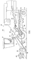
- FIG. 1 a schematic side elevational view, partially in cross section, of a crop harvesting machine 10, commonly referred to as a self-propelled combine harvester, can be seen.
- the combine base unit 11 comprises a wheeled frame or housing 12 mobilely supported on a front pair of traction wheels 13 and a rear pair of steerable wheels 14 for movement over a field to harvest crop material. Pivotally mounted to the front of the base unit 11 is a feeder house 15 on the front of which is mounted a crop harvesting header 16 of conventional design.
- the header 16 includes a forwardly disposed reciprocating cutterbar 18 for severing crop material from the stubble.
- a reel 20 is disposed above and forwardly of the cutterbar 18 to sweep crop material thereover and transport it rearwardly to a consolidating auger 22 where it is converged centrally of the machine and then elevated by an elevator 24 of conventional construction in the feeder house 15 to threshing and separating means indicated generally at 26.
- the threshing and separating means 26 consist of a threshing cylinder 28 and a straw beater 30, provided respectively with cooperating concave means 32 and 34, and a set of longitudinally extending straw walkers 36.
- deflector means 37 comprising an additional rotor 38, are provided of which the function will be described furtheron.
- threshing cylinder 28 and associated concave means 32 Most of the grain is separated from the straw by the threshing cylinder 28 and associated concave means 32. Straw material issuing from the threshing means 28, 32 is subjected to the action of the straw beater 30 and passes therefrom to the straw walkers 36 which effect further separation of grain from the remainder of the crop material. Wanted grain together with chaff material which are separated through the concave means 32 and 34, fall onto a conveyor 40 and are transported towards a cleaning apparatus 42, which comprises sieve means 44 and a cleaning fan 46.
- the sieve means 44 are oscillated generally back-and-forth for moving the grain therealong while permitting the passage of cleaned grain by gravity therethrough.
- the grain on the sieve means 44 is subjected to a cleaning action by the fan 46 which serves to blow air through said sieve means 44 in order to remove the chaff and other impurities, such as dust , from the grain by making this material airborne for discharge from the machine. Clean grain is collected underneath the sieve means 44 from where it subsequently is transferred to a grain tank 48 on top of the combine base unit 11.
- the elevator 24 in the feeder house 15 is in the form of an endless chain and slat apron conveyor comprising transverse slats 50.
- the apron conveyor 24 is driven by a drive shaft 52 positioned at the rearward end 54 of the feeder house 15, the sense of rotation being such that the conveyor 24 operates in an undershot manner, i.e. crop material engaged thereby is conveyed upwardly inbetween the underside of the apron conveyor 24 and a bottom plate 56 of the feeder house 15.
- the orientation of the feeder house 15 relative to the combine base unit 11 and hence the height of the header 16 relative to the ground is controlled by a pair of hydraulic lift cylinders 58 (shown in Figure 1) interconnecting the feeder house 15 and the base unit 11. By extending the cylinders 58 and pivoting the feeder house 15 about the drive shaft 52, the header 16 can be lifted from the ground.
- Crop material transported by the conveyor 24 travels through a crop discharge opening 60 at the rear end 54 of the feeder house 15 towards the rotor 38 already referred to.
- An important function of the rotor 38 is to act as a deflector beater for deflecting the layer of crop material issuing at the discharge opening 60 towards an inlet gap 62 between the threshing cylinder or drum 28 and the concave means 32 and located slightly below the horizontal plane through the centre of the drum 28.
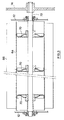
- the deflector beater 38 has a tubular body 64 on which deflector plates 66 are mounted at equiangularly spaced intervals, the plates 66 extending the full length of the body 64 and being secured thereto by bolts 68.
- the tubular body 64 is formed by two half-cylindrical parts, each having a recessed portion at only one longitudinal side thereof for receiving the non-recessed side of the adjacent part and whereby both parts are bolted to flanges 70 provide at the inner side of the body 64.
- weld nuts are secured to the inner side of both said parts receiving the bolts 68, thereby increasing serviceability of the deflector plates 66.
- the deflector beater 38 is drivingly connected to a shaft 72, extending centrally through the flanges 70 and rotatably supported by the side walls of the combine frame 12, at one side of which a pulley 74 is provided for driving the shaft 72 in a direction as indicated by arrow 75.
- the apron conveyor 24 transports crop material upwardly in a dense layer since the transport area is confined by the bottom wall 56 on the one hand and the lower run of said conveyor 24 moving closely above the bottom wall 56 on the other hand. It has been found essential for the efficiency of the deflector beater 38 to present this layer of crop material to the beater 38 still in a dense, confined manner as, under such conditions, the beater 38 has the most effective impact on said layer. If, on the contrary, the layer of crop material would be allowed to expand freely in front of the beater 38, then the operation of the latter would be hampered in that the beater 38 would have to recompress the layer before transporting it further and hence energy would be lost.
- the detaining element 82 further is disposed to extend towards the deflector beater 38, whereby a gap 86 is build of a width preferably equal to the distance measured between the slats 50 of the lower run of the conveyor 24 and the bottom plate 56, so as to preserve a constant thickness of the layer of crop material along its path around the beater 38.
- the curvature of the top portion 84 of the detaining element 82 serves a threefold purpose.
- the front part of the top portion 84 ensures a smooth reception of crop material leaving the feeder house 15, even if the orientation of the latter is varied during operation.
- the rearward part of the top portion 84 defines, in conjunction with the beater 38, the width of the discharge gap 86 and finally, the transitional part between the front and rearward parts helps to fluently divert the layer of crop material from its initial upwardly inclined direction 76 towards its downwardly inclined direction 80.
- Layer expansion in an upward direction in the transitional area between the conveyor 24 and the beater 38 is substantially prevented by providing the beater 38 in the immediate vicinity of the outline generated by the conveyor slats 50, so that said transitional area is kept confined.
- the beater 38 acts as a scraper element to reduce back-feeding of crop material over the conveyor 24.
- the trajectory 80 of the crop towards the inlet gap 62 thus mainly is determined by the cooperating action of the deflector beater 38 on the one hand and the crop detaining element 82 on the other hand; the latter element 82 being fixedly secured to the combine frame 12 and hence having a fixed orientation relative to the deflector beater 38. Consequently, if the working orientation of the feeder house 15 relative to the combine frame 12 is altered e.g. due to providing larger or smaller sized tyres, the crop trajectory behind the deflector beater 38 is hardly influenced.
- each plate 66 may vary therefrom. Preferably however, this number is not reduced below four, in order to ensure a controlled grip of the plates 66 on the layer of crop material.
- the angle ⁇ of each plate 66 to the tangent of the body 64 is approximately 30°. Although this angle has been found suitable, it should be understood that other angles are possible and that also the shape of the deflector plates 66 may be varied substantially.
- the plates 66 may be wound spirally around the tubular body 64; each plate 66 comprising two oppositely wound flights which extend from the middle of the deflector beater 38 towards each respective end thereof. Such an arrangement could be advantageous for spreading the crop more evenly over the inlet 62 of the threshing cylinder 28 when the elevator 24 is unevenly loaded.
- the threshing cylinder 28 Rearwardly of the deflector beater 38, the threshing cylinder 28 is provided, which comprises flanges 88 and raspbars 90 mounted thereon.
- the threshing cylinder 28 is rotated in the direction of arrow 92 around axis 93, extending parallel to but at a lower level relative to as well the shaft 72 of the beater 38 as the drive shaft 52 of the apron conveyor 24.
- the threshing cylinder 28 partially is positioned underneath the deflector beater 38 for, on the one hand, reducing the distance between the discharge end 54 of the feeder house 15 and the threshing inlet 62, and, on the other hand, enlarging the available space inbetween the feeder house 15 and the threshing cylinder 28 in order to create the possibility to mount a deflector beater 38 with a considerable diameter, so as to optimize the impact thereof on the transported layer of crop.
- the concave means 32 extending around the threshing cylinder 28 over an angle of approximately 180°, is composed of two individual concave portions : a leading concave 94 at the inlet of the concave means 32 and a trailing concave 96 at the outlet thereof.
- the leading concave 94 comprises transverse threshing bars 98 mounted edge-on in a frame with arcuate side members 100 and front and rear transverse bars 101.
- curved slats and wires are provided parallel to the side members 100.
- the main function thereof nevertheless consists in threshing the harvested crop material, as can be seen from the aggressive positioning of the threshing bars 98 which extend beyond the curved upper surface of the side members 100.
- the leading concave 94 is adjustable relative to the threshing cylinder 28 for adjusting the clearance therebetween to suit the type of harvested crop and the crop condition; a clearance which may vary from a few millimetres for harvesting small seeds to about 40 mm for harvesting corn.
- the concave 94 is adjustably supported at its forward and rearward end and is adjustable by actuation of a rod and bell crank arrangement generally indicated by the chain line 102, either manually operated from the operators cab 17 or by a remote controlled electric actuator (not shown).
- a transition beam 104 Rigidly attached to the front transverse bar 101 of the concave 94 is a transition beam 104 with an angled upper surface of which one side slants downwardly towards the inlet gap 62 in order to constitute a guiding surface for the crop material which is projected from the deflector beater 38.
- an additional rasp bar 106 on the upper surface of the beam 104 with the rasps thereof facing in the direction of the threshing cylinder 28 in a manner such that the rotating rasp bars 90 of the latter cooperate with the stationary rasp bar 106 to already effect a fierce threshing action before the crop reaches the threshing concave 94.
- the transition beam 104 is shaped to directly receive the additional rasp bar 106 and orient it correctly without the need of any connecting joints.
- the rasps on said rasp bar 106 not necessarily extend parallel to the fore-and-aft axis of the combine harvester, but may diverge from the middle towards the respective sides thereof to, on the one hand, improve the threshing effect and, on the other hand, induce a spreading effect on the layer of crop material.
- the leading concave 94 envelops the threshing cylinder 28 over an arc of approximately 100° which is a commonly used dimension for a threshing concave.
- the threshing cylinder 28 is provided with a further concave 96 which closely adheres to and extends from the leading concave 94 over a further arc of approximately 80°.
- Said concave 96 comprises front and rear transverse bars 108, transverse slats 109 and arcuate side members 110 with curved slats and wires (not shown) inbetween.
- both concaves 94 and 96 look rather similar.
- the transverse slats 109 do not extend beyond the curved, upper surface defined by the arcuate side members 110 and therefore are not aggressive on the layer of crop passing thereover. Furthermore, the circumferential distance measured between adjacent transverse slats 109 on the one hand and the transversely measured distance between adjacent fore-and-aft extending wires on the other hand are twice as large as the corresponding distances measured on the leading concave 94. It thus will be appreciated that, although some threshing activity still is experienced between the cylinder 28 and the concave 96, the latter in essence acts as a separating grid for separating the wanted grain from the straw material.
- the trailing concave 96 has a front portion concentrically positioned relative to the cylinder 28, while a rearward portion at the outlet of said concave 96 flares radially outwardly relative thereto in order to attenuate the transition with the concave 34 underneath the straw beater 30.
- said outlet of the concave 96 is located slightly above the horizontal plane through the axis 93 of the drum 28.
- said leading concave (94) may be adjusted askew relative to the threshing cylinder (28) whereby the clearance inbetween diminishes from the inlet gap (62) towards the outlet of said concave (94).
- the clearance at said outlet preferably is taken identical to the clearance of the trailing concave (96) so as to obtain a soft transition between both concaves (94 and 96).
- the position of the threshing cylinder 28 relative to respectively the deflector beater 38 and the straw beater 30 has been chosen such that the outlines generated by said rotating elements closely approach one another.
- the deflector beater 38 is combed off at its rearward side by the cylinder 28 while the straw beater 30 in turn does the same on the backside of the cylinder 28.
- This configuration aims to avoid backfeeding and wrapping of straw material around the rotary structures.
- rigid scraper plates 114 have been provided above the cylinder 28 to further improve the foregoing action.
- the diameter of the deflector beater 38 is about the two thirds of the diameter of the threshing drum 28, so that the latter is able to comb off a rather substantial area of the former.
- Crop material issuing from the threshing cylinder 28 is guided by the straw beater 30 over the concave 34 towards the straw walkers 36, meanwhile further separating grain from the straw material.
- the straw beater 30 may be constructed partially or even completely identical to the deflector beater 38.
- the rotary elements of the threshing and separating mechanism 26 are all either directly or indirectly driven from a common main drive shaft (not shown) of the combine harvester 10, which rotates at about 1000 RPM under full load of the combine harvester engine. All said rotary elements are coupled in pairs in the following sequence.
- a first drive, extending from the main drive shaft to the straw beater 30, comprises a variator mechanism so that the drive speed of the straw beater 30 may be varied from 480 RPM to 1425 RPM.
- the straw beater 30 in turn drives the threshing cylinder 28 in a range from 420 RPM to 1250 RPM.
- the deflector beater 38 is driven from the threshing cylinder 28 at a speed varying from 140 RPM to 420 RPM.
- an additional speed reducer is operatively interconnected between the main drive shaft and the beater 30 so that the drive speed of all the rotors in front thereof are reduced by half.
- the drive shaft 52 of the straw elevator 24 is directly coupled to the main drive shaft and as such is driven at a fixed speed of 390 RPM.
- deflector beater 38 Since the deflector beater 38 is drivingly dependent from the threshing cylinder 28, any variation of the drive speed of the latter automatically results in a corresponding change in speed of the former, gearing the operation for one another under all conditions.
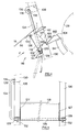
- the stone trap 116 comprises a transversely extending shaped plate having a downwardly inclined front face 118, an almost vertical portion 120 and a rearwardly and upwardly inclined portion 122. In alignment with the portion 122 and extending towards the front, a bridging plate 124 is provided. The front plate 118, together with the plate 124 and the rearward portion 122, define a V-shaped trough in which the foreign objects are collected.
- the bent edges on the front plate 118 and the rearward portion 122 are intended to give greater strength to the structure.
- side walls 127 are provided at the transverse opposite ends thereof.
- the front plate 118 carries a flexible sealing strip 131 which shoulders against the bottom plate 56 of the feeder house 15 in whatever position thereof.
- the stone trap 116 is pivotable as a unitary structure around a transverse pivot axis at the inner side of the bent between the front plate 118 and the portion 120.
- Shaft means 128, either comprising stub shafts (not shown) at each side of the stone trap 116 or a single elongate rod 128, as depicted in Figure 4, are coincident with said pivot axis and are pivotally supported by two U-shaped brackets 129 attached to the front frame members 130. Keys 132 are inserted through aligned apertures in the limbs of the brackets 129 to hold the shaft 128 in place.
- the shaft or rod 128 is welded or otherwise secured at the bottom end of the front plate 118 across the transverse width thereof.
- the stone trap 116 can be moved between a stone-collecting position and a stone-dumping position, respectively shown in full and dashed lines in Figure 4, by means of a handle 134 at the right hand side of the combine harvester 10.
- Said handle 134 may be attached to any part of the stone trap 116, but preferably is formed by an elongate extension of the rod 128, extending at a right angle relative thereto.
- the top portion 135 of the handle 134 is bent inwardly, parallel to the front face of the right hand side frame member 130, in order to form an abutment for the handle 134 when the stone trap 116 is closed.
- a latch member 136 with an open-ended curved slot 138 is pivotally attached at 139 to the frame member 130 for retaining the stone trap 116 in its stone-collecting position.
- the stone trap 116 can easily be emptied by unlatching the latch member 136 and manually pulling the handle 134 forwardly to thereby pivot the stone trap 116 to its stone-dumping position.
- an electric or hydraulic actuator may be connected to the handle 134, enabling the combine operator to pivot the stone trap 116 back and forth between its open and closed positions without leaving the cab. In such an arrangement, the latch member 136 would not be required.
- crop material conveyed towards the threshing cylinder 28 has to cross a transversely extending open space which is formed by the stone trap inlet 140. Accordingly, once the crop material has been impelled and released by the deflector beater 38 through the gap 86 with the detaining element 82, it is freely flowing across said inlet 140 towards the threshing cylinder 28, without being guided by a rigid wall element.
- the conveyor 40 is housed in a self-supporting frame or housing 142 comprising a bottom wall 144, a semicircular front wall 146 and side walls 148 which are interconnected by a pair of transversely extending reinforcement beams 150.
- the conveyor 40 is driven in a clockwise direction as seen in Figure 1, or otherwise said, the conveyor 40 is of the so called "overshot" type which means that the crop is conveyed at the upper side thereof.
- a drag board 164 spanning the total width of the conveyor 40 and covering the shafts 156 and 157 with bent end portions 166, is rigidly attached to the beams 150 in order to form a stationary, upwardly and rearwardly inclined floor over which the crop is urged by the impelling action of the strips 162.
- Said end portions 166 prevent contact between the transported crop material and the shafts 156, 157 in order to keep the latter clean even under adverse harvesting conditions, whereby the grain and chaff material may be mixed with wet and sticky particles of soil and seeds of weed. It has been experienced that under such harvesting conditions, also the drag board 164 is not prone of contamination as the flexible strips 162 sweep the upper surface thereof while transporting the crop.
- the distance between successive strips 162 on the one hand and the height of these strips 162 on the other hand have been chosen in relation to as well the fore-and-aft inclination of the conveyor 40 (which is approximately 45°) as the drive speed thereof for optimizing the transport capacity of the arrangement under various operating conditions.
- the shaft 157 at the lower, receiving end of the conveyor 40 does not rotate during operation and is fixedly supported by brackets 167, slidably attached to the side walls 148 by intermediary of a conventional tensioning mechanism (not shown) for taking up eventual stretch of the chains 152.
- brackets 167 As the shaft 157 is stationary, the corresponding sprockets 154 are rotatably carried thereon. Contrary thereto, the upper shaft 156 at the discharge end of the conveyor 40 imparts rotation to the latter and therefore the corresponding sprockets are fixedly connected thereto.
- Brackets 168, rotatably supporting the shaft 156 are incorporated in the side walls 148 of the conveyor housing 142 and, in turn, are held by further brackets 170 united with opposite side members of the combine frame 12.
- a stub shaft 172 having a conical portion 173 and a threaded end 174, is screwed into a receiving seat provided in the shaft 156 at one side thereof.
- a sprocket 176 which is fitted on the stub shaft 172, is incorporated in a drive train (not shown) of the combine harvester for driving the conveyor 40 at a speed of approximately 1 m/sec.
- both lateral sides of the conveyor 40 are each others mirror image, except for what the drive arrangement 172, 176 is concerned, only the side thereof containing said drive arrangement 172, 176 has been shown in Figure 7.
- brackets 168 supporting the upper shaft 156 are slidably received by the brackets 170 enabling the conveyor 40 to be pivoted as a unitary structure around the coincident axis of the shaft 156 between an operative, material receiving position and an inoperative, retracted position, respectively shown in full and phantom lines in Figure 6.
- a screw jack 178 or any other type of suitable actuator is interconnected between a rigid transverse beam 180 of the combine frame 12, located at the back side of the conveyor 40, and an anchoring point proximate to the lowermost part of the conveyor housing 142; the screw jack 178 being operable to change the relative position of said housing 142 by being retracted or extended from an easy accessible location at the side of the combine harvester 10.
- additional locking means for securing the housing 142 in one of its extreme positions are not really required since the screw jack 178 can be blocked in any desired position, they nevertheless may be provided to further improve safety.
- the combine frame 12 transversely extends beyond the conveyor housing 142 and hence encloses the latter.
- the drive shaft 156 is deprived from its drive arrangement 172, 176, the conveyor 40 can be slid into the combine frame 12 as a unit, whereafter the brackets 170 are partially inserted through apertures in said frame 12 for receiving the brackets 168 and hence supporting the complete conveyor 40.
- the stub shaft 172, carrying the sprocket 176 is screwed into the shaft 156 for drivingly connecting the latter to a drive arrangement of the combine harvester, as already mentioned.
- Flexible strips (not shown) seal off any eventual apertures which may exist between the lateral sides of the conveyor housing 142, when in the grain receiving position, and the inner lateral sides of the combine frame 12, the foregoing to avoid any loss of grain therethrough during harvesting operation.
- the upper transverse end of the housings front wall 146 engages a sealing strip 182 attached to a slanting plate 183 fixed to the traction beam 184 of the harvester 10.
- Inspection cover means in the form of an inspection door 186, are pivotally attached at 187 to the traction beam 184; said door 186, when in a closed position, extending in alignment with the plate 183 towards the lowermost edge of the stone trap 116 and held in that position by latch means which are not shown.
- a reception plate 90 is operable to guide grain and chaff material issuing from said conveyor 40 towards the cleaning apparatus 42, comprising a.o. a conventional corrugated grain pan 192 and conventional sieves 44.
- the complete cleaning apparatus 42 is supported by a generally rectangular sub frame 194 which is pivotally mounted at its forward and rearward ends (only the forward end 195 being indicated) on the frame 12 of the combine harvester 10.
- position control means are operable to automatically pivot the sub frame 194 so as to maintain the cleaning apparatus 42 horizontal, as seen in a transverse direction.
- the overall configuration of the threshing and separating means 26, the cleaning apparatus 42 and the intermediate conveyor 40 displays the following peculiar features.
- the inlet gap 62 of the concave means 32 is located proximate to the horizontal median plane of the threshing cylinder 38, harvested crop material has to be fed in from an upward location.
- the cleaning mechanism 42 as a unitary structure is pivotable around a fore-and-aft extending axis for permitting said structure to be pivoted to a substantially horizontal position, when the combine harvester is transversely inclined relative to the vertical. It readily will be appreciated that during pivotal movement of the cleaning mechanism 42 from a non-pivoted position to an extreme pivoted position, the longitudinally extending sides of said cleaning mechanism 42 travel a considerable distance along the interior of the combine frame 12, demanding ample free space above the cleaning mechanism for allowing unobstructed swivelling thereof.
- the slanting front side of the trough 196 is operable to direct any separated material which falls thereon towards the lowermost material receiving end of the conveyor 40, which transfers this material, together with material directly received from the concaves 94 and 96, upwardly and rearwardly towards the front of the cleaning mechanism 42.
- the interior of the trough 196 and hence the threshing and separating means 26, in particular the threshing cylinder 28 and the concave means 32, and also the grain transporting side of the conveyor 40, are readily accessible for servicing from different sides of the trough 196 by means already referred to above. Indeed, by pivoting the conveyor 40 towards its retracted position abutting thereby the transverse frame beam 180, the rearward side of the trough is partially opened at its lowermost end, creating an aperture between the slanting plate 183 at the back side of the traction beam 184 and the lower part of the conveyor 40.
- the semicircular extending concaves 94 and 96 thereby become readily accessible in a generally vertical, upward direction.
- the lower part of the threshing cylinder 28 can be inspected through the meshes of the concaves 94 and 96 or may be reached for eventual repair by removing said concaves 94,96.
- Access to the threshing means 26 thus also can be gained from between the traction beam 184 and the feeder house 15, preferably with the latter in its raised, inoperative position. Accessibility through the front side of the trough is still further improved by removing the stone trap 116, what simply can be done by unlatching the latch member 136 and extracting the keys 132 from the stone trap supporting brackets 129.
- the crop detaining element 82 is also detachably supported by the combine frame 12 so that after removal of said element 82 also the discharge end of the crop elevator 24 and the deflector beater 38 easily can be reached.
- the inspection door 186 does not stop short of the bottom edge of the stone trap 116, but comprises an extended plate 197 therebehind which engages an upper surface of the transition beam 104.
- the plate 197 effectively substitutes the bottom wall 122, 124 of the stone trap 116 as depicted in Figure 4.
- the alternative stone trap 116 therefore only needs a simplified structure comprising in essence the side walls 127 and the front plate 118, which has been enveloped around and fixedly attached to the pivot shaft 128.
- the stone trap 116 is relatively light, and thus removal thereof is easily and rapidly accomplished, whereafter the door 186 falls open automatically. Accordingly, by unlatching only one element, being the stone trap 116, a full access through the front side of the trough 196 is obtained.
- the threshing and separating means 26, in particular the deflector beater 38, the concaves 94,96 and the threshing cylinder 28 are easily accessible thanks to the partial incorporation of these elements in the trough 196 of which as well the front side as the rear side can be opened and/or removed. All this further implies that the threshing means become accessible from different sides at the same time. Consequently, when the nature of eventual servicing or repair would require the combined effort of several people, the trough 196 may be opened at both transverse sides so that those people simultaneously can gain access into the trough 196 from different sides allowing them to help each other.
Priority Applications (2)
| Application Number | Priority Date | Filing Date | Title |
|---|---|---|---|
| DE1991621086 DE69121086T2 (de) | 1991-06-04 | 1991-06-04 | Steinauffangvorrichtung für Mähdrescher |
| EP19910201361 EP0516892B1 (fr) | 1991-06-04 | 1991-06-04 | Trappe à pierres pour moissonneuse-batteuse |
Applications Claiming Priority (1)
| Application Number | Priority Date | Filing Date | Title |
|---|---|---|---|
| EP19910201361 EP0516892B1 (fr) | 1991-06-04 | 1991-06-04 | Trappe à pierres pour moissonneuse-batteuse |
Publications (2)
| Publication Number | Publication Date |
|---|---|
| EP0516892A1 true EP0516892A1 (fr) | 1992-12-09 |
| EP0516892B1 EP0516892B1 (fr) | 1996-07-24 |
Family
ID=8207694
Family Applications (1)
| Application Number | Title | Priority Date | Filing Date |
|---|---|---|---|
| EP19910201361 Expired - Lifetime EP0516892B1 (fr) | 1991-06-04 | 1991-06-04 | Trappe à pierres pour moissonneuse-batteuse |
Country Status (2)
| Country | Link |
|---|---|
| EP (1) | EP0516892B1 (fr) |
| DE (1) | DE69121086T2 (fr) |
Cited By (5)
| Publication number | Priority date | Publication date | Assignee | Title |
|---|---|---|---|---|
| US5702300A (en) * | 1996-04-18 | 1997-12-30 | Agco Corporation | Combine rock door over center closure apparatus |
| EP1530895A1 (fr) * | 2003-11-14 | 2005-05-18 | Deere & Company | Moissoneuse batteuse à recueil de cailloux |
| EP2294909A1 (fr) * | 2009-09-15 | 2011-03-16 | CLAAS Selbstfahrende Erntemaschinen GmbH | Trappe à cailloux |
| US9986687B2 (en) | 2014-10-20 | 2018-06-05 | Cnh Industrial America Llc | Stone trap assembly for a harvester |
| US10405492B2 (en) | 2017-06-19 | 2019-09-10 | Cnh Industrial America Llc | Self-cleaning rock sump for an agricultural harvester and related systems and methods |
Citations (8)
| Publication number | Priority date | Publication date | Assignee | Title |
|---|---|---|---|---|
| US3433230A (en) * | 1966-03-10 | 1969-03-18 | Case Co J I | Stone trap for combines |
| US3576188A (en) * | 1969-04-18 | 1971-04-27 | Int Harvester Co | Pivot dumping stone trap |
| DE2024706A1 (de) * | 1970-05-21 | 1971-12-23 | Maschinenfabrik Fahr Ag, 7702 Gottmadingen | Steinauffangvorrichtung für Erntemaschinen, insbesondere Mähdrescher |
| FR2349274A1 (fr) * | 1974-06-03 | 1977-11-25 | Clayson Nv | Trappe a cailloux pour moissonneuse-batteuse |
| US4335562A (en) * | 1980-12-29 | 1982-06-22 | Meyers Alma D | Rock trap for farm vehicle |
| US4404975A (en) * | 1981-11-25 | 1983-09-20 | Westby Roger L | Rock trap for a combine |
| EP0096923B1 (fr) * | 1982-06-15 | 1986-12-30 | Ford New Holland N.V. | Trappe à cailloux pour moissonneuse-batteuse |
| US4657029A (en) * | 1986-01-31 | 1987-04-14 | Massey Combines Corporation | Stone trap for a combine harvester |
-
1991
- 1991-06-04 EP EP19910201361 patent/EP0516892B1/fr not_active Expired - Lifetime
- 1991-06-04 DE DE1991621086 patent/DE69121086T2/de not_active Expired - Fee Related
Patent Citations (8)
| Publication number | Priority date | Publication date | Assignee | Title |
|---|---|---|---|---|
| US3433230A (en) * | 1966-03-10 | 1969-03-18 | Case Co J I | Stone trap for combines |
| US3576188A (en) * | 1969-04-18 | 1971-04-27 | Int Harvester Co | Pivot dumping stone trap |
| DE2024706A1 (de) * | 1970-05-21 | 1971-12-23 | Maschinenfabrik Fahr Ag, 7702 Gottmadingen | Steinauffangvorrichtung für Erntemaschinen, insbesondere Mähdrescher |
| FR2349274A1 (fr) * | 1974-06-03 | 1977-11-25 | Clayson Nv | Trappe a cailloux pour moissonneuse-batteuse |
| US4335562A (en) * | 1980-12-29 | 1982-06-22 | Meyers Alma D | Rock trap for farm vehicle |
| US4404975A (en) * | 1981-11-25 | 1983-09-20 | Westby Roger L | Rock trap for a combine |
| EP0096923B1 (fr) * | 1982-06-15 | 1986-12-30 | Ford New Holland N.V. | Trappe à cailloux pour moissonneuse-batteuse |
| US4657029A (en) * | 1986-01-31 | 1987-04-14 | Massey Combines Corporation | Stone trap for a combine harvester |
Cited By (5)
| Publication number | Priority date | Publication date | Assignee | Title |
|---|---|---|---|---|
| US5702300A (en) * | 1996-04-18 | 1997-12-30 | Agco Corporation | Combine rock door over center closure apparatus |
| EP1530895A1 (fr) * | 2003-11-14 | 2005-05-18 | Deere & Company | Moissoneuse batteuse à recueil de cailloux |
| EP2294909A1 (fr) * | 2009-09-15 | 2011-03-16 | CLAAS Selbstfahrende Erntemaschinen GmbH | Trappe à cailloux |
| US9986687B2 (en) | 2014-10-20 | 2018-06-05 | Cnh Industrial America Llc | Stone trap assembly for a harvester |
| US10405492B2 (en) | 2017-06-19 | 2019-09-10 | Cnh Industrial America Llc | Self-cleaning rock sump for an agricultural harvester and related systems and methods |
Also Published As
| Publication number | Publication date |
|---|---|
| EP0516892B1 (fr) | 1996-07-24 |
| DE69121086T2 (de) | 1996-12-19 |
| DE69121086D1 (de) | 1996-08-29 |
Similar Documents
| Publication | Publication Date | Title |
|---|---|---|
| US5624315A (en) | Cleaning means for an agricultural harvesting machine | |
| EP1162873B1 (fr) | Perfectionnements apportes a des moissonneuses-batteuses a flux axial | |
| US3593719A (en) | Combine with three-stage separation | |
| US6945023B2 (en) | Shielding means for an elevator of an agricultural harvesting machine | |
| EP1201112B1 (fr) | Réservoir à grain d'une moissonneuse | |
| RU2540536C2 (ru) | Устройство для повторного обмолота недомолоченных колосков | |
| US4208858A (en) | Isolated pneumatic cleaning system | |
| US5324231A (en) | Stone trap for a combine harvester | |
| US4552547A (en) | Straw chopper drive | |
| US7654892B2 (en) | Tailings re-thresher deflector | |
| EP0516894B1 (fr) | Dispositif batteur à contre-batteur en deux parties | |
| EP0516889B1 (fr) | Dispositif déflecteur devant le dispositif de battage d'une moissonneuse-batteuse | |
| US4510948A (en) | Discharge assist means for combine harvesters | |
| RU2709763C2 (ru) | Сельскохозяйственная уборочная машина с вращающимся элеватором | |
| EP0516893B1 (fr) | Moyen d'accès au dispositif batteur d'une moissonneuse-batteuse | |
| EP0516892B1 (fr) | Trappe à pierres pour moissonneuse-batteuse | |
| US11291160B2 (en) | Agricultural harvester and a dust extractor for the agricultural harvester | |
| EP0516891B1 (fr) | Elévateur pivotant à grains et menues pailles | |
| EP0516890A1 (fr) | Elévateur à grains et menues pailles pour moissonneuse-batteuse | |
| EP0117591A1 (fr) | Moissonneuse-batteuse | |
| JP2000060278A (ja) | コンバイン | |
| JPH11332352A (ja) | コンバイン | |
| JPH0343016A (ja) | コンバイン |
Legal Events
| Date | Code | Title | Description |
|---|---|---|---|
| PUAI | Public reference made under article 153(3) epc to a published international application that has entered the european phase |
Free format text: ORIGINAL CODE: 0009012 |
|
| AK | Designated contracting states |
Kind code of ref document: A1 Designated state(s): DE FR GB |
|
| RAP1 | Party data changed (applicant data changed or rights of an application transferred) |
Owner name: NEW HOLLAND BELGIUM N.V. |
|
| 17P | Request for examination filed |
Effective date: 19930618 |
|
| R17P | Request for examination filed (corrected) |
Effective date: 19930802 |
|
| 17Q | First examination report despatched |
Effective date: 19941018 |
|
| GRAH | Despatch of communication of intention to grant a patent |
Free format text: ORIGINAL CODE: EPIDOS IGRA |
|
| GRAA | (expected) grant |
Free format text: ORIGINAL CODE: 0009210 |
|
| AK | Designated contracting states |
Kind code of ref document: B1 Designated state(s): DE FR GB |
|
| REF | Corresponds to: |
Ref document number: 69121086 Country of ref document: DE Date of ref document: 19960829 |
|
| ET | Fr: translation filed | ||
| PLBE | No opposition filed within time limit |
Free format text: ORIGINAL CODE: 0009261 |
|
| STAA | Information on the status of an ep patent application or granted ep patent |
Free format text: STATUS: NO OPPOSITION FILED WITHIN TIME LIMIT |
|
| 26N | No opposition filed | ||
| REG | Reference to a national code |
Ref country code: GB Ref legal event code: IF02 |
|
| REG | Reference to a national code |
Ref country code: FR Ref legal event code: CD |
|
| PGFP | Annual fee paid to national office [announced via postgrant information from national office to epo] |
Ref country code: DE Payment date: 20050401 Year of fee payment: 15 |
|
| PG25 | Lapsed in a contracting state [announced via postgrant information from national office to epo] |
Ref country code: DE Free format text: LAPSE BECAUSE OF NON-PAYMENT OF DUE FEES Effective date: 20070103 |
|
| PGFP | Annual fee paid to national office [announced via postgrant information from national office to epo] |
Ref country code: FR Payment date: 20080407 Year of fee payment: 18 |
|
| PGFP | Annual fee paid to national office [announced via postgrant information from national office to epo] |
Ref country code: GB Payment date: 20080410 Year of fee payment: 18 |
|
| GBPC | Gb: european patent ceased through non-payment of renewal fee |
Effective date: 20090604 |
|
| REG | Reference to a national code |
Ref country code: FR Ref legal event code: ST Effective date: 20100226 |
|
| PG25 | Lapsed in a contracting state [announced via postgrant information from national office to epo] |
Ref country code: FR Free format text: LAPSE BECAUSE OF NON-PAYMENT OF DUE FEES Effective date: 20090630 |
|
| PG25 | Lapsed in a contracting state [announced via postgrant information from national office to epo] |
Ref country code: GB Free format text: LAPSE BECAUSE OF NON-PAYMENT OF DUE FEES Effective date: 20090604 |