EP0516639B1 - Device for applying lengths or pieces of fabric - Google Patents
Device for applying lengths or pieces of fabric Download PDFInfo
- Publication number
- EP0516639B1 EP0516639B1 EP91903248A EP91903248A EP0516639B1 EP 0516639 B1 EP0516639 B1 EP 0516639B1 EP 91903248 A EP91903248 A EP 91903248A EP 91903248 A EP91903248 A EP 91903248A EP 0516639 B1 EP0516639 B1 EP 0516639B1
- Authority
- EP
- European Patent Office
- Prior art keywords
- pile
- edge
- runners
- fabric
- section
- Prior art date
- Legal status (The legal status is an assumption and is not a legal conclusion. Google has not performed a legal analysis and makes no representation as to the accuracy of the status listed.)
- Expired - Lifetime
Links
Images
Classifications
-
- D—TEXTILES; PAPER
- D05—SEWING; EMBROIDERING; TUFTING
- D05B—SEWING
- D05B35/00—Work-feeding or -handling elements not otherwise provided for
- D05B35/10—Edge guides
Definitions
- the invention relates to a device for applying fabric or fabric sections, in particular fabrics that are coated on both sides with pile and then have a floreless zone (smooth fabric) to the pile zone to feed these fabric or fabric sections in particular to a seaming and sewing station that with a conveyor consisting of a pair of belts is equipped (see US-A-3 457 885).
- coated with pile should be understood to mean any desired thickening of a fabric, such as terry cloth, loop or tufted goods or the like. Difficulties have arisen in the processing of such goods insofar as, in particular when hemming and sewing, no exact fit of the hem or the seam on the pile edge could be achieved without special care on the part of the operator. The latter costs time and money.
- the invention is therefore based on the object of providing a device for applying such webs of material during seaming and sewing, which makes it possible that the hem to be formed lies exactly against the pile and no pile loops are sewn into the hem.
- the device according to the invention shows a simple and inexpensive way to process terry toweling to be hemmed so that the seam and seam lie exactly against the pile edge. Sewing in pile loops is safely avoided.
- the device allows high processing speeds with low demands on the skill of the operator, who can work with a tolerance of up to about 4 mm with respect to the reference line when inserting the fabric web, because the edges of the runners are designed so that the pile is always from the florid zone is pushed away.
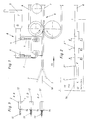
- Figure 1 shows the device in side view. It is designed as a ballast 8, which is connected upstream of a conveyor 9 and is attached to the machine frame via a fastening 5.
- An essential part of the device are two runners 1, 2, of which the runners 1 are suspended on the ballast 8 as a rigid support underneath the web 10 and the runners 2.
- the contact pressure of the runner 2 can be changed with bolts 4, which act on springs 3.
- the conveyor 9 consists, in a manner known per se, of two endless belts 6, 7, which take up the fabric web 10 on their contact surface and convey it in the direction of the arrow 13 to a hemming and sewing station (not shown).
- the fabric web 10 to be inserted is manually drawn between the two runners 1, 2. Behind the runners 1, 2, the fabric web 10 is taken over by the belts 6, 7 of the conveying device 9, the plane between the two runners 1, 2 and the two belt parts 6, 7 touching each other being at the same height.
- FIG. 2 shows the device in plan view.
- the fabric web 10 which consists of a pile zone 11 and a pile zone 12 (smooth fabric), has a pile edge 14, along which the goods are to be hemmed and sewn.
- the top view is the runner 2 can also be seen, while the runner 1 underneath is covered by the fabric web 10.
- the runners 1 and 2 are essentially of the same design, and the lower runners 1 can be shorter. Its edge facing the pile edge 14 is stepped in such a way that a narrow beginning section 2 'adjoins a slope 2''and is followed by a curved section 2''' which reaches over the pile edge 14 at its end.
- Figure 3 shows three sections A-B, C-D, E-F of Figure 2.
- the section A-B is performed in the second stage, it shows the two runners 1, 2 as they push back the pile edge 14 of the pile zone 11 with its pointed bevel.
- the blunt runner edge has reached the pile edge 14 and in section E-F the runner edge is arrow-shaped, as seen from the pile zone 11, its outer edges projecting beyond the pile edge 14.
Landscapes
- Engineering & Computer Science (AREA)
- Textile Engineering (AREA)
- Treatment Of Fiber Materials (AREA)
- Sewing Machines And Sewing (AREA)
- Vending Machines For Individual Products (AREA)
- Management, Administration, Business Operations System, And Electronic Commerce (AREA)
- Agricultural Machines (AREA)
- Transplanting Machines (AREA)
- Glass Compositions (AREA)
- Exhaust Gas Treatment By Means Of Catalyst (AREA)
- Chemical Or Physical Treatment Of Fibers (AREA)
Abstract
Description
Die Erfindung betrifft eine Vorrichtung zum Anlegen von Stoffbahnen oder Stoffbahnabschnitten, insbesondere von Stoffen, die beidseitig mit Flor beschichtet sind und anschließend an die Florzone eine florlose Zone (Glattgewebe) aufweisen, um diese Stoffbahnen oder Stoffbahnabschnitte insbesondere einer Säum- und Nähstation zuzuführen, die mit einer aus einem Riemenpaar bestehenden Fördereinrichtung ausgestattet ist (siehe US-A-3 457 885).The invention relates to a device for applying fabric or fabric sections, in particular fabrics that are coated on both sides with pile and then have a floreless zone (smooth fabric) to the pile zone to feed these fabric or fabric sections in particular to a seaming and sewing station that with a conveyor consisting of a pair of belts is equipped (see US-A-3 457 885).
Unter den Begriff "mit Flor beschichtet" sollen alle beliebigen Verdickungen eines Gewebes, wie Frotteeware, Schlingen- oder Büschelware oder dergleichen verstanden werden.
Bei der Verarbeitung von solchen Waren haben sich insofern Schwierigkeiten ergeben, als insbesondere beim Säumen und Nähen kein exaktes Anliegen des Saumes bzw. der Naht an der Florkante zu erreichen war, ohne besondere Sorgfalt seitens der Bedienungsperson aufzuwenden. Letzteres kostet aber Zeit und Geld.The term "coated with pile" should be understood to mean any desired thickening of a fabric, such as terry cloth, loop or tufted goods or the like.
Difficulties have arisen in the processing of such goods insofar as, in particular when hemming and sewing, no exact fit of the hem or the seam on the pile edge could be achieved without special care on the part of the operator. The latter costs time and money.
Der Erfindung liegt deshalb die Aufgabe zugrunde, eine Vorrichtung zum Anlegen derartiger Stoffbahnen beim Säumen und Nähen zu schaffen, die es ermöglicht, daß der zu bildende Saum exakt am Flor anliegt und keine Florschlaufen in den Saum vernäht werden.The invention is therefore based on the object of providing a device for applying such webs of material during seaming and sewing, which makes it possible that the hem to be formed lies exactly against the pile and no pile loops are sewn into the hem.
Zur Lösung dieser Aufgabe dienen die im Hauptanspruch gekennzeichneten Merkmale. Die Unteransprüche enthalten zweckmäßige weitere Ausbildungen.The features characterized in the main claim serve to solve this problem. The sub-claims contain useful further training.
Die erfindungsgemäße Vorrichtung zeigt einen einfachen und kostengünstigen Weg, zu säumende Frotteeware so zu verarbeiten, daß Saum und Naht genau an der Florkante anliegen. Das Einnähen von Florschleifen wird sicher vermieden. Die Vorrichtung läßt hohe Verarbeitungsgeschwindigkeiten bei geringen Anforderungen an die Geschicklichkeit der Bedienungsperson zu, die beim Einlegen der Stoffbahn mit einer Toleranz bis zu ca. 4 mm hinsichtlich der Bezugslinie arbeiten kann, weil die Kanten der Kufen so ausgebildet sind, daß der Flor immer von der florlosen Zone abgedrängt wird.The device according to the invention shows a simple and inexpensive way to process terry toweling to be hemmed so that the seam and seam lie exactly against the pile edge. Sewing in pile loops is safely avoided. The device allows high processing speeds with low demands on the skill of the operator, who can work with a tolerance of up to about 4 mm with respect to the reference line when inserting the fabric web, because the edges of the runners are designed so that the pile is always from the florid zone is pushed away.
In den Zeichnungen ist ein Ausführungsbeispiel der erfindungsgemäßen Vorrichtung dargestellt.In the drawings, an embodiment of the device according to the invention is shown.
Es zeigen:
- Fig. 1
- eine Seitenansicht der Vorrichtung;
- Fig. 2
- eine Draufsicht auf die Vorrichtung nach Figur 1;
- Fig. 3
- Schnittdarstellungen von Fig. 2.
- Fig. 1
- a side view of the device;
- Fig. 2
- a plan view of the device of Figure 1;
- Fig. 3
- Sectional views of Fig. 2nd
Figur 1 zeigt die Vorrichtung in Seitenansicht. Sie ist als Vorschaltgerät 8 ausgeführt, das einer Fördereinrichtung 9 vorgeschaltet ist und über eine Befestigung 5 am Maschinenrahmen angebracht ist. Wesentlicher Bestandteil der Vorrichtung sind zwei Kufen 1, 2, von denen die Kufe 1 als starre Auflage unterhalb der Warenbahn 10 und die Kufe 2 federnd am Vorschaltgerät 8 aufgehängt ist. Der Anpreßdruck der Kufe 2 kann mit Schraubbolzen 4, die auf Federn 3 einwirken, verändert werden. Die Fördereinrichtung 9 besteht in an sich bekannter Weise aus zwei endlosen Riemen 6, 7, die an ihrer Berührungsfläche die Stoffbahn 10 aufnehmen und in Richtung des Pfeiles 13 zu einer (nicht gezeigten) Säum- und Nähstation befördern. Die einzulegende Stoffbahn 10 wird manuell zwischen die beiden Kufen 1,2 gezogen. Hinter den Kufen 1,2 wird die Stoffbahn 10 von den Riemen 6,7 der Fördereinrichtung 9 übernommen, wobei die Ebene zwischen den beiden Kufen 1,2 und den beiden sich berührenden Riementeilen 6,7 auf gleicher Höhe liegt.Figure 1 shows the device in side view. It is designed as a
Figur 2 zeigt die Vorrichtung in Draufsicht. Die Stoffbahn 10, die aus einer Florzone 11 und einer florlosen Zone 12 (Glattgewebe) besteht, weist eine Florkante 14 auf, längs der die Ware gesäumt und genäht werden soll. In der Draufsicht ist auch die Kufe 2 zu sehen, während die darunterliegende Kufe 1 von der Stoffbahn 10 verdeckt ist. Die Kufen 1 und 2 sind im wesentlichen gleich ausgestaltet, wobei die untere Kufe 1 kürzer sein kann. Ihre, der Florkante 14 zugewandte Kante ist stufenförmig derart abgesetzt, daß auf einen schmalen Anfangsabschnitt 2' über eine Schräge 2'' ein kurvenförmiger Abschnitt 2''' anschließt, der an seinem Ende über die Florkante 14 hinüber- greift. Dadurch wird es ermöglicht, daß die Bedienungsperson beim Einlegen der Ware keine besondere Sorgfalt beachten muß, sie kann die Ware auch so einlegen, daß die Florkante 14 in Richtung zur Kufe 2 verschoben ist; durch die stufenförmige Ausgestaltung der Kufenkante erfolgt immer ein genaues Ausrichten bis zum Einlauf der Ware in die Fördereinrichtung 9.Figure 2 shows the device in plan view. The
Figur 3 zeigt drei Schnitte A-B, C-D, E-F von Figur 2. Der Schnitt A-B ist in der zweiten Stufe geführt, er zeigt die beiden Kufen 1,2, wie sie die Florkante 14 der Florzone 11 mit ihrer spitzen Abschrägung zurückdrängen. Im nächsten Schnitt C-D hat die stumpfe Kufenkante die Florkante 14 erreicht und im Schnitt E-F ist die Kufenkante, von der Florzone 11 gesehen, pfeilförmig ausgebildet, wobei ihre Außenkanten über die Florkante 14 überstehen.Figure 3 shows three sections A-B, C-D, E-F of Figure 2. The section A-B is performed in the second stage, it shows the two
Claims (4)
- A device for applying fabric lengths or portions of fabric lengths, in particular fabrics which are covered on both sides with pile and next to the area of pile display a pile-free area (smooth-surface woven fabric), in order to convey these fabric lengths or portions of fabric lengths in particular to a hemming or sewing station, which is equipped with a conveying device consisting of a pair of belts, whereby at its entrance a preceding device fixed to the machine framework is disposed, which comprises two guide components, the lower one of which is fixed, while the upper guide component is suspended in a sprung manner,
characterised in that the guide components ending at the entry of the fabric length (10) into the conveying device (9) consist of runners (1, 2), which are stepped with respect to the pile edge (14), which is formed at the transition from the pile area (17 ) to the pile-free area (12), so that after a narrow initial portion (2') via an inclined portion (2'') there follows a curved portion (2'''), whereby the initial portion (2') is spaced from the pile edge (14) and via the inclined portion (2'') approaches the pile edge (14), which is finally reached in portion (2''') so that the pile edge (14) abuts one edge of the runners (1, 2 ). - A device according to Claim 1,
characterised in that in the initial portion (2'; 2''; section A-B) the edges of the runners (1, 2) are slanted in an arrow shape and protrude towards the pile edge (14),
in that in the next portion (2'''; section C-D) the edges of the runners (1, 2) have a blunt construction,
and in that in the region of section (E-F), seen from the area of pile (11), the edges of the runners (1, 2) seen in the direction of the arrow (13) behind section (C-D) are constructed in an arrow shape, whereby their outer edges protrude over the pile edge (14). - A device according to Claim 1 or 2,
characterised in that a variable pressure can be applied to the runner (2) with its springs (3) via screw bolts (4). - A device according to one of Claims 1 to 3, characterised in that in the direction of the arrow (13) of the advancing fabric length (10) the two runners (1, 2) are provided in a per se known manner with upwardly bent shoes.
Priority Applications (1)
| Application Number | Priority Date | Filing Date | Title |
|---|---|---|---|
| AT91903248T ATE99007T1 (en) | 1990-02-22 | 1991-02-14 | DEVICE FOR APPLYING FABRIC PANELS OR PANELS. |
Applications Claiming Priority (2)
| Application Number | Priority Date | Filing Date | Title |
|---|---|---|---|
| DE9002121U DE9002121U1 (en) | 1990-02-22 | 1990-02-22 | |
| DE9002121U | 1990-02-22 |
Publications (2)
| Publication Number | Publication Date |
|---|---|
| EP0516639A1 EP0516639A1 (en) | 1992-12-09 |
| EP0516639B1 true EP0516639B1 (en) | 1993-12-22 |
Family
ID=6851290
Family Applications (1)
| Application Number | Title | Priority Date | Filing Date |
|---|---|---|---|
| EP91903248A Expired - Lifetime EP0516639B1 (en) | 1990-02-22 | 1991-02-14 | Device for applying lengths or pieces of fabric |
Country Status (8)
| Country | Link |
|---|---|
| US (1) | US5282433A (en) |
| EP (1) | EP0516639B1 (en) |
| AT (1) | ATE99007T1 (en) |
| AU (1) | AU7231691A (en) |
| BR (1) | BR9105933A (en) |
| DE (4) | DE9002121U1 (en) |
| ES (1) | ES2048586T3 (en) |
| WO (1) | WO1991013198A1 (en) |
Families Citing this family (9)
| Publication number | Priority date | Publication date | Assignee | Title |
|---|---|---|---|---|
| US6000352A (en) * | 1997-10-15 | 1999-12-14 | Porter Sewing Machines, Inc. | Method and apparatus for sewing fabric panels |
| US6415727B1 (en) | 1998-03-09 | 2002-07-09 | Diversified Systems, Inc. | Flanging machine |
| US6834603B1 (en) | 2002-03-05 | 2004-12-28 | Atlanta Attachment Company | Attachment gusset with ruffled corners and system for automated manufacture of same |
| US6802271B2 (en) | 2003-01-08 | 2004-10-12 | Atlanta Attachment Company | Automatic border sewing system |
| US7100525B1 (en) | 2003-02-10 | 2006-09-05 | Atlanta Attachment Company, Inc. | System and method of finishing ruffled gussets/borders |
| US6968794B1 (en) | 2003-04-03 | 2005-11-29 | Atlanta Attachment Company | Presser foot control system |
| US7543364B1 (en) | 2004-01-13 | 2009-06-09 | Atlanta Attachment Company | Border flanging and attachment gusset forming system |
| US7383780B1 (en) | 2005-04-18 | 2008-06-10 | Atlanta Attachment Company | Tape edge work station |
| US7984681B1 (en) | 2007-11-20 | 2011-07-26 | Atlanta Attachment Company | Automatic panel sewing and flanging system |
Family Cites Families (8)
| Publication number | Priority date | Publication date | Assignee | Title |
|---|---|---|---|---|
| US1093185A (en) * | 1913-04-18 | 1914-04-14 | John Hudson | Sewing-machine attachment. |
| US1093105A (en) * | 1913-05-26 | 1914-04-14 | Harry E Boyd | Collapsible core. |
| US3450075A (en) * | 1967-07-07 | 1969-06-17 | Martinsburg Mills Inc | Apparatus for closing the toe portion of circular knit hosiery |
| FR1550345A (en) * | 1967-11-07 | 1968-12-20 | ||
| US3527181A (en) * | 1968-06-25 | 1970-09-08 | Hanes Corp | Fabric guiding means for sewing machines |
| DE3227198C2 (en) * | 1982-07-21 | 1985-03-07 | Carl Schmale Kg, 4434 Ochtrup | Material feed device on a sewing machine |
| DE3412385C1 (en) * | 1984-04-03 | 1985-10-24 | Texpa Arbter-Maschinenbau GmbH, 8741 Saal | Device for processing at least one longitudinal edge of a material web |
| DE9016341U1 (en) * | 1990-12-01 | 1991-02-21 | Carl Schmale Gmbh & Co Kg, 4434 Ochtrup, De |
-
1990
- 1990-02-22 DE DE9002121U patent/DE9002121U1/de not_active Expired - Lifetime
-
1991
- 1991-02-14 BR BR919105933A patent/BR9105933A/en not_active IP Right Cessation
- 1991-02-14 US US07/849,429 patent/US5282433A/en not_active Expired - Fee Related
- 1991-02-14 DE DE19914190402 patent/DE4190402A1/en not_active Ceased
- 1991-02-14 DE DE91DE9100118D patent/DE4190402D2/en not_active Expired - Lifetime
- 1991-02-14 AU AU72316/91A patent/AU7231691A/en not_active Abandoned
- 1991-02-14 DE DE91903248T patent/DE59100752D1/en not_active Expired - Fee Related
- 1991-02-14 ES ES91903248T patent/ES2048586T3/en not_active Expired - Lifetime
- 1991-02-14 EP EP91903248A patent/EP0516639B1/en not_active Expired - Lifetime
- 1991-02-14 AT AT91903248T patent/ATE99007T1/en not_active IP Right Cessation
- 1991-02-14 WO PCT/DE1991/000118 patent/WO1991013198A1/en active IP Right Grant
Also Published As
| Publication number | Publication date |
|---|---|
| WO1991013198A1 (en) | 1991-09-05 |
| EP0516639A1 (en) | 1992-12-09 |
| ES2048586T3 (en) | 1994-03-16 |
| US5282433A (en) | 1994-02-01 |
| AU7231691A (en) | 1991-09-18 |
| DE9002121U1 (en) | 1990-05-03 |
| ATE99007T1 (en) | 1994-01-15 |
| DE4190402D2 (en) | 1992-12-10 |
| BR9105933A (en) | 1992-11-24 |
| DE4190402A1 (en) | 1992-12-10 |
| DE59100752D1 (en) | 1994-02-03 |
Similar Documents
| Publication | Publication Date | Title |
|---|---|---|
| EP0516639B1 (en) | Device for applying lengths or pieces of fabric | |
| EP0576664B1 (en) | Process and device for preparing socks whose tips are sewn together | |
| DE2326421C3 (en) | Method and apparatus for sewing a series of zipper links to a fabric | |
| EP0559668B1 (en) | Process for hemming fabric webs and hemming device for a fabric web sewing installation, in particular for terry fabrics | |
| DE20317988U1 (en) | Multiple needle sewing machine | |
| DE2543987A1 (en) | FINE CONVEYORS FOR BELT CONVEYORS, IN PARTICULAR FINE COAL CONVEYORS FOR CHAIN SCRAPER CONVEYORS | |
| DE2815599C2 (en) | Device for folding items of laundry | |
| DE3334646C2 (en) | Device for folding and positioning tape sections on pieces of fabric | |
| EP0722518B1 (en) | Method and device for hemming continuous strips of textile fabric | |
| DE3040286A1 (en) | METHOD AND SEWING MACHINE FOR RECEIVING A ZIPPER LINK CHAIN | |
| DE2228955A1 (en) | Presser foot for zippers | |
| DE2129139A1 (en) | Method and apparatus for the manufacture of slide fasteners from an uninterrupted fastening chain | |
| DE1610728A1 (en) | Method of making woven clothes belts | |
| DE3227198A1 (en) | SEWING MATERIAL FEEDING DEVICE ON A SEWING MACHINE | |
| DE2621239A1 (en) | LAYOUT FOR A FABRIC MAKING MACHINE | |
| DE92666C (en) | ||
| DE221910C (en) | ||
| DE3540819C1 (en) | Linking machine with a device for supplying a binding tape | |
| DE2403333A1 (en) | Broad non-woven felting layer - developed by opening out strips of fibre material from a carding unit | |
| AT385788B (en) | Trimming device for textile materials having offset edge strips | |
| DE3731334C2 (en) | ||
| DE2344184A1 (en) | METHOD OF SEWING A ZIPPER INTO A SLOTED CLOTHING, ZIPPER TAPE SUITABLE FOR THE METHOD AND ZIPPER SUITABLE FOR THE METHOD | |
| DE7710677U1 (en) | DEVICE PROVIDED FOR ON A BAR SEWING MACHINE FOR TURNING THE END OF THREAD CHAIN TO BE TAPPED | |
| EP1424430A2 (en) | Method for feeding laundry pieces to a laundry treatment apparatus, in particular to a mangle, and corresponding device | |
| DE7531184U (en) | FINE COAL CONVEYORS FOR CHAIN SCRAPER CONVEYORS |
Legal Events
| Date | Code | Title | Description |
|---|---|---|---|
| PUAI | Public reference made under article 153(3) epc to a published international application that has entered the european phase |
Free format text: ORIGINAL CODE: 0009012 |
|
| 17P | Request for examination filed |
Effective date: 19920220 |
|
| AK | Designated contracting states |
Kind code of ref document: A1 Designated state(s): AT BE CH DE DK ES FR GB IT LI LU NL SE |
|
| 17Q | First examination report despatched |
Effective date: 19930604 |
|
| GRAA | (expected) grant |
Free format text: ORIGINAL CODE: 0009210 |
|
| AK | Designated contracting states |
Kind code of ref document: B1 Designated state(s): AT BE CH DE DK ES FR GB IT LI LU NL SE |
|
| PG25 | Lapsed in a contracting state [announced via postgrant information from national office to epo] |
Ref country code: NL Effective date: 19931222 Ref country code: DK Effective date: 19931222 Ref country code: BE Effective date: 19931222 |
|
| REF | Corresponds to: |
Ref document number: 99007 Country of ref document: AT Date of ref document: 19940115 Kind code of ref document: T |
|
| ET | Fr: translation filed | ||
| GBT | Gb: translation of ep patent filed (gb section 77(6)(a)/1977) |
Effective date: 19931221 |
|
| REF | Corresponds to: |
Ref document number: 59100752 Country of ref document: DE Date of ref document: 19940203 |
|
| PG25 | Lapsed in a contracting state [announced via postgrant information from national office to epo] |
Ref country code: LU Free format text: LAPSE BECAUSE OF NON-PAYMENT OF DUE FEES Effective date: 19940228 |
|
| ITF | It: translation for a ep patent filed |
Owner name: MODIANO & ASSOCIATI S.R.L. |
|
| REG | Reference to a national code |
Ref country code: ES Ref legal event code: FG2A Ref document number: 2048586 Country of ref document: ES Kind code of ref document: T3 |
|
| NLV1 | Nl: lapsed or annulled due to failure to fulfill the requirements of art. 29p and 29m of the patents act | ||
| PLBE | No opposition filed within time limit |
Free format text: ORIGINAL CODE: 0009261 |
|
| STAA | Information on the status of an ep patent application or granted ep patent |
Free format text: STATUS: NO OPPOSITION FILED WITHIN TIME LIMIT |
|
| 26N | No opposition filed | ||
| EAL | Se: european patent in force in sweden |
Ref document number: 91903248.2 |
|
| REG | Reference to a national code |
Ref country code: CH Ref legal event code: PUE Owner name: CARL SCHMALE GMBH & CO. TRANSFER- SCHMALE-HOLDING Ref country code: CH Ref legal event code: PFA Free format text: CARL SCHMALE GMBH & CO. KG TRANSFER- CARL SCHMALE GMBH & CO. |
|
| REG | Reference to a national code |
Ref country code: FR Ref legal event code: TP |
|
| REG | Reference to a national code |
Ref country code: ES Ref legal event code: PC2A |
|
| REG | Reference to a national code |
Ref country code: GB Ref legal event code: IF02 |
|
| PGFP | Annual fee paid to national office [announced via postgrant information from national office to epo] |
Ref country code: FR Payment date: 20020118 Year of fee payment: 12 |
|
| PGFP | Annual fee paid to national office [announced via postgrant information from national office to epo] |
Ref country code: ES Payment date: 20020124 Year of fee payment: 12 |
|
| PGFP | Annual fee paid to national office [announced via postgrant information from national office to epo] |
Ref country code: SE Payment date: 20020130 Year of fee payment: 12 |
|
| PGFP | Annual fee paid to national office [announced via postgrant information from national office to epo] |
Ref country code: GB Payment date: 20020211 Year of fee payment: 12 |
|
| PGFP | Annual fee paid to national office [announced via postgrant information from national office to epo] |
Ref country code: DE Payment date: 20020227 Year of fee payment: 12 |
|
| PGFP | Annual fee paid to national office [announced via postgrant information from national office to epo] |
Ref country code: AT Payment date: 20020228 Year of fee payment: 12 |
|
| PGFP | Annual fee paid to national office [announced via postgrant information from national office to epo] |
Ref country code: CH Payment date: 20020425 Year of fee payment: 12 |
|
| PG25 | Lapsed in a contracting state [announced via postgrant information from national office to epo] |
Ref country code: GB Free format text: LAPSE BECAUSE OF NON-PAYMENT OF DUE FEES Effective date: 20030214 Ref country code: AT Free format text: LAPSE BECAUSE OF NON-PAYMENT OF DUE FEES Effective date: 20030214 |
|
| PG25 | Lapsed in a contracting state [announced via postgrant information from national office to epo] |
Ref country code: SE Free format text: LAPSE BECAUSE OF NON-PAYMENT OF DUE FEES Effective date: 20030215 Ref country code: ES Free format text: LAPSE BECAUSE OF NON-PAYMENT OF DUE FEES Effective date: 20030215 |
|
| PG25 | Lapsed in a contracting state [announced via postgrant information from national office to epo] |
Ref country code: LI Free format text: LAPSE BECAUSE OF NON-PAYMENT OF DUE FEES Effective date: 20030228 Ref country code: CH Free format text: LAPSE BECAUSE OF NON-PAYMENT OF DUE FEES Effective date: 20030228 |
|
| PG25 | Lapsed in a contracting state [announced via postgrant information from national office to epo] |
Ref country code: DE Free format text: LAPSE BECAUSE OF NON-PAYMENT OF DUE FEES Effective date: 20030902 |
|
| EUG | Se: european patent has lapsed | ||
| GBPC | Gb: european patent ceased through non-payment of renewal fee | ||
| REG | Reference to a national code |
Ref country code: CH Ref legal event code: PL |
|
| PG25 | Lapsed in a contracting state [announced via postgrant information from national office to epo] |
Ref country code: FR Free format text: LAPSE BECAUSE OF NON-PAYMENT OF DUE FEES Effective date: 20031031 |
|
| REG | Reference to a national code |
Ref country code: FR Ref legal event code: ST |
|
| REG | Reference to a national code |
Ref country code: ES Ref legal event code: FD2A Effective date: 20030215 |
|
| PG25 | Lapsed in a contracting state [announced via postgrant information from national office to epo] |
Ref country code: IT Free format text: LAPSE BECAUSE OF NON-PAYMENT OF DUE FEES;WARNING: LAPSES OF ITALIAN PATENTS WITH EFFECTIVE DATE BEFORE 2007 MAY HAVE OCCURRED AT ANY TIME BEFORE 2007. THE CORRECT EFFECTIVE DATE MAY BE DIFFERENT FROM THE ONE RECORDED. Effective date: 20050214 |