EP0516467A2 - A compacting press with a polymer powder heating and feeding system - Google Patents
A compacting press with a polymer powder heating and feeding system Download PDFInfo
- Publication number
- EP0516467A2 EP0516467A2 EP92304942A EP92304942A EP0516467A2 EP 0516467 A2 EP0516467 A2 EP 0516467A2 EP 92304942 A EP92304942 A EP 92304942A EP 92304942 A EP92304942 A EP 92304942A EP 0516467 A2 EP0516467 A2 EP 0516467A2
- Authority
- EP
- European Patent Office
- Prior art keywords
- shuttle
- assembly
- hopper
- powder
- auger conveyor
- Prior art date
- Legal status (The legal status is an assumption and is not a legal conclusion. Google has not performed a legal analysis and makes no representation as to the accuracy of the status listed.)
- Granted
Links
Images


Classifications
-
- B—PERFORMING OPERATIONS; TRANSPORTING
- B29—WORKING OF PLASTICS; WORKING OF SUBSTANCES IN A PLASTIC STATE IN GENERAL
- B29C—SHAPING OR JOINING OF PLASTICS; SHAPING OF MATERIAL IN A PLASTIC STATE, NOT OTHERWISE PROVIDED FOR; AFTER-TREATMENT OF THE SHAPED PRODUCTS, e.g. REPAIRING
- B29C43/00—Compression moulding, i.e. applying external pressure to flow the moulding material; Apparatus therefor
- B29C43/32—Component parts, details or accessories; Auxiliary operations
- B29C43/34—Feeding the material to the mould or the compression means
-
- B—PERFORMING OPERATIONS; TRANSPORTING
- B29—WORKING OF PLASTICS; WORKING OF SUBSTANCES IN A PLASTIC STATE IN GENERAL
- B29C—SHAPING OR JOINING OF PLASTICS; SHAPING OF MATERIAL IN A PLASTIC STATE, NOT OTHERWISE PROVIDED FOR; AFTER-TREATMENT OF THE SHAPED PRODUCTS, e.g. REPAIRING
- B29C43/00—Compression moulding, i.e. applying external pressure to flow the moulding material; Apparatus therefor
- B29C43/006—Pressing and sintering powders, granules or fibres
-
- B—PERFORMING OPERATIONS; TRANSPORTING
- B30—PRESSES
- B30B—PRESSES IN GENERAL
- B30B15/00—Details of, or accessories for, presses; Auxiliary measures in connection with pressing
- B30B15/30—Feeding material to presses
- B30B15/302—Feeding material in particulate or plastic state to moulding presses
- B30B15/304—Feeding material in particulate or plastic state to moulding presses by using feed frames or shoes with relative movement with regard to the mould or moulds
-
- B—PERFORMING OPERATIONS; TRANSPORTING
- B29—WORKING OF PLASTICS; WORKING OF SUBSTANCES IN A PLASTIC STATE IN GENERAL
- B29C—SHAPING OR JOINING OF PLASTICS; SHAPING OF MATERIAL IN A PLASTIC STATE, NOT OTHERWISE PROVIDED FOR; AFTER-TREATMENT OF THE SHAPED PRODUCTS, e.g. REPAIRING
- B29C43/00—Compression moulding, i.e. applying external pressure to flow the moulding material; Apparatus therefor
- B29C43/02—Compression moulding, i.e. applying external pressure to flow the moulding material; Apparatus therefor of articles of definite length, i.e. discrete articles
- B29C43/04—Compression moulding, i.e. applying external pressure to flow the moulding material; Apparatus therefor of articles of definite length, i.e. discrete articles using movable moulds
- B29C2043/046—Compression moulding, i.e. applying external pressure to flow the moulding material; Apparatus therefor of articles of definite length, i.e. discrete articles using movable moulds travelling between different stations, e.g. feeding, moulding, curing stations
-
- B—PERFORMING OPERATIONS; TRANSPORTING
- B29—WORKING OF PLASTICS; WORKING OF SUBSTANCES IN A PLASTIC STATE IN GENERAL
- B29K—INDEXING SCHEME ASSOCIATED WITH SUBCLASSES B29B, B29C OR B29D, RELATING TO MOULDING MATERIALS OR TO MATERIALS FOR MOULDS, REINFORCEMENTS, FILLERS OR PREFORMED PARTS, e.g. INSERTS
- B29K2105/00—Condition, form or state of moulded material or of the material to be shaped
- B29K2105/25—Solid
- B29K2105/251—Particles, powder or granules
Definitions
- the invention relates to a system which will accept a variety of polymer coated powders of metal and other materials, heat each particle to a temperature just below the coagulation point, and feed the heated powders accurately into a heated die cavity on a conventional compacting press.
- the powder is directed from a storage hopper by means of a flexible hose to the hopper of a delivery shuttle by which the powder is shifted to a die cavity in a measured amount.
- Difficulties are encountered, however, when attempting to use the same sort of delivery system for polymer coated powder wherein the powder is delivered to a heated die and held for a time sufficient to heat the powder to its desired temperature before the compacting operation.
- this approach is very time consuming.
- it causes localized overheating where the powder is in contact with the heated die.
- the polymer coating acts as a temperature insulator, and those coated particles in the interior of the mass are slow to heat, while the polymer-coated particles adjacent the heated die "set" before the interior particles are hot enough to compact.
- the present invention is directed to a coated powder delivery system which will overcome the above- noted problems.
- the delivery system of the present invention will accept a variety of polymer coated powders of metal or other materials. Each coated particle is heated to a temperature just below the coagulation point. The heated powders are accurately fed into a heated die cavity on a conventional compacting press. The remaining increase in temperature to the "set" point is then rapidly achieved during a standard compacting cycle by a combination of the heated tooling and the energy imparted during the actual compacting stroke.
- a system for heating and feeding polymer coated powder into a heated die.cavity of a compacting press comprising at least one auger assembly and at least one shuttle assembly.
- the at least one auger assembly comprises a vertical pipe and a horizontally oriented auger conveyor.
- the auger conveyor has an entry port and a discharge end.
- the vertical pipe has an upper end releasably connected to a source of the polymer coated powder.
- the vertical pipe has a lower end connected to the entry port of the horizontal auger conveyor.
- the vertical pipe has a heating element wrapped about its periphery.
- the auger conveyor has a first heating element wrapped about its periphery and extending from its entry port toward its discharge end.
- the auger conveyor has a second heating element extending from the first heating element to its discharge end.
- the vertical pipe heater imparts heat to the polymer coated powder.
- the auger conveyor heaters impart heat to the individual powder particles through a mixing action.
- the shuttle assembly comprises a fixed portion supporting a heated shuttle hopper, and a movable portion supporting a heated powder ring.
- the discharge end of the auger conveyor is located over the fixed hopper of the shuttle assembly.
- the movable portion of the shuttle assembly is shiftable between a retracted position wherein the upper end of the powder ring is coaxial with and open to the shuttle hopper and the lower end of the powder ring is closed, and an extended position wherein the lower end of the powder ring is coaxial with and open to the die cavity of the compacting press and the discharge end of the shuttle hopper is closed.
- the heaters of the vertical tube, the auger conveyor, the shuttle hopper and the shuttle powder ring heat the individual particles of the polymer coated powder to a temperature just below the coagulation point thereof.
- two substantially identical auger assemblies are provided, each having a discharge end located over the fixed hopper of the shuttle assembly. In normal operation, both auger assemblies operate simultaneously.
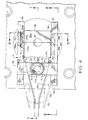
- FIG. 1 is a simplified plan view of the polymer coated powder feed system of the present invention.
- the feed system comprises a pair of substantially identical auger assemblies generally indicated at 1 and 2, respectively.
- the auger assemblies 1 and 2 are mounted on support assemblies generally indicated at 3 and 4, respectively.
- the support assemblies 3 and 4 are ad- justably mounted on a tubular steel bracket 5.
- the bracket 5, is affixed to the frame (not shown) of a conventional compacting press.
- the feed system of the present invention also includes a shuttle assembly, generally indicated at 6, and mounted on the die supporting assembly 7 of the compacting press.
- the movable portion of the shuttle assembly 6 is shiftable longitudinally between a retracted position and an extended position by a shuttle actuating assembly generally indicated at 8.
- the shuttle actuating assembly 8 in turn, is supported on the bracket 5.
- the auger assembly 1 comprises a horizontal tube 9, the rearward end of which is supported in a mounting block 10. Near the mounting block 10, the horizontal tube 9 has an opening 11 formed therein to receive the lower end of a vertical tube 12.
- the vertical tube 12 is welded or otherwise appropriately affixed to the horizontal tube 9 and is additionally supported by a plate 13.
- the plate 13 is affixed to mounting block 10 by a series of cap screws 14.
- the forward end of plate 13 is bifurcated and the vertical tube 12 is received between the bifurcations.
- a retainer plate 15 extends across the ends of the bifurcations and is affixed thereto by a pair of cap screws 16.
- the vertical tube 12 is wrapped throughout the majority of its length by insulation 17 and a heating element 18.
- that portion of horizontal tube 9 extending forwardly of vertical tube 12 is wrapped by a pair of insulation elements 19 and 20, and a pair of heating elements 21 and 22. It will be noted that the heating element 19 is somewhat longer than the heating element 20.
- inner tube 23 Mounted within horizontal tube 9 there is an inner tube 23.
- the forwardmost end of inner tube 23 extends slightly beyond the forward end of horizontal tube 9.
- the rearward end of inner tube 23 is affixed to a shaft 24 as at 25.
- the shaft 24 carries a sealing ring 26 forming a seal between the shaft and the horizontal tube 9.
- the assembly of the shaft 24 and the inner tube 23 is rotatable within horizontal tube 9 by virtue of bearings 27 and 28.
- the rearward end of shaft 24 is connected to a coupling 29, as is shown in Figures 2 and 3.
- the inner tube 23 is surrounded by a helical spring 30.
- the forward end of the helical spring 30 is welded to the inner tube forward end as at 31.
- the rearward end of helical spring 30 is engaged on the shaft 24 adjacent seal 26.
- the helical spring 30 rotates with inner tube 23 and shaft 24 within horizontal tube 9 and converts the inner tube 23 and shaft 24 into an auger.
- the coupling 29 is connected to the shaft 32 of an electric motor 33.
- Electric motor 33 is provided with a mounting bracket 34.
- the mounting bracket 34 is attached by cap screws 35 to drive mounting plate 36.
- Mounting block 10 is provided with a thrust bearing 37 and a cover plate 38 for shaft 24.
- the mounting block 10 rests upon a heat insulative plate 39.
- the cap screws 14 extend through plate 13, mounting block 10, insulative plate 39 and into drive mounting plate 36.
- Drive mounting plate 36 overlies a lower mounting plate 40.
- the drive mounting plate 36 and lower mounting plate 40 are joined together at their rearward edges by a hinge 41, the purpose of which will be apparent hereinafter.
- the support assembly 3 for the auger assembly 1 comprises an elongated upwardly and rearwardly extending arm 42. As is most clearly seen in Figure 2, the upper end of arm 42 terminates in a horizontal end plate 43.
- the lower mounting plate 40 is affixed to upper end plate 43 by three cap screws 44 (see Figure 1). Each of the cap screws 44 passes through an elongated slot 45 in lower mounting plate 40 and is threadedly engaged in the upper end plate 43.
- the drive mounting plate 36 is provided with elongated and enlarged openings 46, providing access to cap screws 44 and their respective slots 45. This arrangement enables the auger assembly 1 to be adjusted in position to assure that the forwardmost end of horizontal tube 9 is properly located with respect to the hopper of the shuttle assembly, to be described hereinafter.
- FIG. 1 The lower end of arm 42 terminates in a vertical mounting plate 47.
- Vertical mounting plate 47 is attached to an adjustable mounting plate 48 by cap screws 49.
- the vertical edges of adjustable mounting plate 48 are provided with a plurality of perforations 50.
- the tubular steel bracket 5 has a pair of horizontal spacers 51 and 52 affixed thereto.
- the adjustable mounting assembly plate 48 is affixed to horizontal spacers 51 and 52 by pairs of cap screws 53 and 54, respectively, passing through selected ones of the adjustable mounting plate perforations 50.
- This arrangement permits a vertical adjustment of auger assembly 1 so that the vertical position of the end of auger assembly tube 9 can be adjusted with respect to the hopper of shuttle assembly 6.
- auger assembly 2 and its support assembly 4 are substantially identical to auger assembly 1 and support assembly 3. To this end, like parts of auger assembly 2 and support assembly 4 have been given the same index numerals as auger assembly 1 and support assembly 3, followed by "a.”
- the auger assembly portion of the present invention is completed by means to introduce a supply of the polymer coated powder into the vertical tubes 12 and 12a of the auger assemblies 1 and 2. Such a means is shown in simplified form in Figure 2.
- a first hopper 55 is provided, into which the operator unloads a supply of the polymer coated powder, as required.
- the hopper 55 has an outlet 56 leading to a second hopper 57 which assures that a constant supply of the polymer coated powder is present.
- the second hopper 57 is provided with an outlet 58 to which a flexible conduit or hose 59 is attached.
- the lower end of the flexible hose 59 is removably affixed to the upper end of vertical tube 12 of auger assembly 1.
- the flexible hose 59 has a hand operated valve 60 located therein by which the supply of polymer coated powder supplied to vertical tube 12 can be started, stopped or regulated.
- the second hopper 57 has a second outlet 61 to which a second flexible hose containing a valve (not shown) will be attached.
- This second hose will be removably connected to the upper end of vertical tube 12a of auger assembly 2, and will function in the same manner.
- connection between the flexible hose 59 and the upper end of vertical tube 12 be readily disconnectable. ltwould be possible, for example, to provide the upper end of vertical tube 12 with a funnel-shaped member into which the lower end of flexible hose 59 loosely extends.
- the entire auger assembly mounted on drive mounting plate 36 can be pivoted rearwardly in a clockwise direction about hinge 41. In this rearwardly pivoted position, auger assembly 1 can be cleaned, serviced or repaired while auger assembly 2 remains in service. It will be understood that auger assembly 2 can similarly be disonnected from its flexible hose (not shown) and pivoted to an out of service position for purposes of cleaning, maintenance and repair.
- the shuttle assembly 6, of Figure 1, mounted on the die supporting assembly 7, will next be described.
- the shuttle assembly 6 comprises a pair of guide walls 62 and 63.
- Guide walls 62 and 63 comprise elongated members removably affixed to the upper surface of the die supporting assembly 7 in parallel spaced relationship and to either side of the die cavity 64.
- the guide walls 62 and 63 may be affixed to the upper surface of the die supporting assembly 7 by any appropriate means such as thumb screws or the like (not shown) so that they may be readily removable.
- the guide walls 62 and 63 support horizontally oriented rails 65 and 66, respectively, the purpose of which will be apparent hereinafter.
- riser blocks 67 and 68 Mounted above rails 65 and 66 is a pair of riser blocks 67 and 68, respectively.
- Riser blocks 67 and 68 support a horizontally oriented hopper plate 69.
- the hopper plate 69 has a central perforation 70 mounting an insulative bushing 71.
- the shuttle assembly 6 is provided with a hopper generally indicated at 72.
- the hopper 72 has an upper cylindrical portion 72a and a lower cylindrical portion 72b of lesser diameter with an annular shoulder 73 formed therebetween.
- the hopper 72 is so located that its lower portion 72b extends through the insulative bushing 71 and its upper portion is located above hopper plate 69, with the annular shoulder 73 resting upon hopper plate 69.
- the upper portion 72a of shuttle hopper 72 is surrounded by a heating element 74.
- the hopper 72 is surrounded by four bolts 75 which extend with clearance through perforations 76 in hopper plate 69.
- the lowermost ends of bolts 75 are threadedly engaged in a sealing and wiping ring 77 which surrounds the lower portion 72b of the shuttle hopper 72.
- Each of the four bolts 75 mounts a compression spring 78.
- Each compression spring has its upper end abutting the underside of hopper plate 69 and its lower end abutting the upper surface of sealing and wiping ring 77.
- the compression springs 78 constantly urge the sealing and wiping ring 77 downwardly. The reason for this arrangement will be apparent hereinafter.
- the hopper plate 69 supports an upstanding bracket 79 (see Figure 6).
- the upstanding bracket 79 supports a probe-like capacitive level sensor 80.
- the sensor 80 has a free end which extends downwardly into the upper portion 72a of the shuttle hopper 72. This last mentioned portion of the sensor senses the height of the polymer coated powder in the upper portion 72a of shuttle hopper 72.
- the shuttle assembly includes a shuttle body 81.
- the shuttle body 81 comprises a thick metallic plate having upstanding side walls 82 and 83 and an upstanding front wall 84 (see Figure 7).
- the base portion of the shuttle body 81 has a circular perforation 85 formed therein.
- the upper edges of the shuttle body side walls 82 and 83 and the shuttle body front wall 84 are coplanar and support an upper cut-off plate 86.
- the upper cut-off plate 86 has a main rectangular portion 86a and a rearwardly directed narrow extended portion 86b.
- the main portion 86a of the upper cut-off plate 86 has a perforation 87 formed therein.
- the perforation 87 is coaxial with the perforation 85 in the shuttle body 81.
- the upper cut-off plate 86 is affixed to the upper edges of shuttle body sides 82 and 83 and the shuttle body front wall 84 by cap screws (not shown) or the like.
- the shuttle body 81 rests upon a lower shuttle plate 88.
- the lower shuttle plate 88 has a perforation 89 therein which is coaxial with the shuttle body perforation 86 and of substantially the same diameter.
- the lower shuttle plate 88 rests upon a bearing plate 90 made up of two distinct parts, a front part 90a and a rear part 90b (see Figure 7).
- the front part 90a of bearing plate 90 has a perforation 91 formed therein which is coaxial with the perforation 85 of shuttle body 81 and the perforation 89 of lower shuttle plate 88, but of lesser diameter. It will be noted from Figures 6 and 7 that the perforation 91 is of slightly lesser diameter than the die cavity 64.
- the two-part bearing plate 90 and the lower shuttle plate 88 are connected together and to the shuttle body 84 by countersunk cap screws (not shown) or the like.
- the shiftable structure thus far described carries a cylindrical powder ring 92.
- the powder ring 92 is open both at its top and at its bottom.
- the powder ring 92 is of a diameter to be just nicely received in the perforation 91 of the front part 90a of bearing plate 90.
- the powder ring 92 Near its lower end, has an annular exterior flange 93 located within the perforation 89 in lower shuttle plate 88 and resting upon the upper surface of the front part 90a of bearing plate 90.
- the powder ring 92 is coaxial with the perforation 87 in upper cut-off plate 86, the perforation 85 in the shuttle body 81, the perforation 89 in lower shuttle plate 88 and the perforation 91 in front portion 90a of bearing plate 90.
- the lower end of powder ring 92 is located just above the bottom surface of the front part 90a of bearing plate 90.
- the upper end of powder ring 92 is located near the lower surface of upper cut-off plate 86.
- An annular silicon spacer 94 forms a seal between the upper end of powder ring 92 and the lower surface of upper cut-off plate 86.
- the powder ring 92 is surrounded by a heating element 95.
- a temperature probe 96 extends into the powder ring and is supported by an appropriate bracket 97 affixed to the underside of upper cut-off plate 86.
- a brass scraper 98 is mounted along the forward edges of lower shuttle plate 88 and the front part 90a of bearing plate 90. Scraper 98 is affixed to the forward edge of lower shuttle plate 88 by appropriate fastening means 99.
- the front wall 84 of shuttle body 81 mounts a block 100 which supports a part deflector 101.
- shuttle body 81 At the rearward end of shuttle body 81 there is mounted a transversely extending block 102 mounted between the rearward portion 86b of upper cut-off plate 86 and lower shuttle plate 88.
- the block 102 carries pivot means 103 by which the forward ends of a shuttle yoke 104 are pivotally connected to the block 102.
- the purpose of shuttle yoke 104 will be apparent hereinafter.
- the lefthand side of the shuttle body 81 supports a roller bar 105.
- the outside surface of the roller bar at the center thereof, is provided with a vertically oriented slot 106.
- the slot 106 is further provided with a vertically elongated perforation 107 adapted to receive a shouldered screw 108 by which roller bar 105 is affixed to the side of shuttle body 81.
- the slot 106 accommodates the head of the shouldered screw 108.
- the elongated perforation 107, in combination with the shouldered screw 108 permits slight vertical shifting of the roller bar 105, as well as pivoting of the roller bar 105 about shouldered screw 108.
- roller bar 105 The ends of roller bar 105 are bifurcated and a pair of rollers 109 and 110 are located between the bifurcations.
- the rollers 109 and 110 are held in place by roll pins 111 and 112, respectively.
- the roll pins 111 and 112 pass through perforations in their respective bifurcations and in their respective rollers 109 and 110. It will be noted that the rollers 109 and 110 are so positioned as to engage the underside of rail 66.
- Adjacent each of the rollers 109 and 110 the roller bar is provided with a socket 113 and 114.
- the lower ends of sockets 113 and 114 are open and the upper ends are closed.
- the sockets 113 and 114 contain compression springs 115 and 116.
- the upper ends of compression springs 115 and 116 abut the closed ends of their respective sockets 113 and 114.
- the lower ends of compression springs 115 and 116 abut the upper surface of lower shuttle plate 88.
- Compression springs 115 and 116 constantly urge the rollers 109 and 110 against the underside of rail 66 and at the same time urge the bearing plate parts 90a and 90b against the upper surface of the die supporting assembly 7.
- roller bar is identical to roller bar 105 and like parts have been given like index numerals followed by "a.”
- the powder ring 92 is coaxial with and open to the die cavity 64, while the bottom end of the shuttle hopper 72 is closed by the extended portion 86b of upper cut-off plate 86.
- FIG. 1 The means for shifting the movable part of the shuttle assembly between its extended and retracted positions is illustrated in Figures 1 and 2.
- a support 117 is mounted on bracket 5, centrally thereof.
- the support 117 mounts a ball screw drive 118 powered by an electric motor 119.
- the shaft 120 of the ball screw drive 118 is pivotally connected as at 121 to the rearward end of the shuttle yoke 104. In this manner, the movable portion of the shuttle assembly is shifted between its extended and retracted positions.
- the heaters 18 and 18a about vertical tubes 12 and 12a are set at a temperature of about 320° F.
- the heaters 21 and 21a about the auger tubes 9 and 9a are set at about 350° F.
- the heaters 22 and 22a about the auger tubes 9 and 9a are set at about 380° F.
- the polymer coated powders feed through vertical tubes 12 and 12a by gravity. As the polymer coated powders pass through the auger tubes 9 and 9a they fill approximately one- third of the tubes so that the powders during theirtrav- el through the auger tubes 9 and 9a are subjected to a stirring effect such that all of the powder particles are appropriately heated.
- the augers are run simultaneously and at such a speed that they operate substantially constantly. It has been found that a cycle of about 6 seconds (i.e., a production rate of about 10 parts per minute) can easily be achieved.
- the auger of the other auger system can be speeded up so that production can be maintained with a minimum reduction in production rate.
- the appropriate ones of the heaters 18, 18a, 21, 21a and 22, 22a can be adjusted to compensate for the increased speed of the auger when just one auger system is operating.
- the movable portion of the shuttle assembly is in its retracted position. This causes the powder ring 92 to be located coaxially beneath the shuttle hopper 72. The bottom of the powder ring 92 will be closed by the upper surface of the die supporting assembly 7. Under these circumstances, the powder within the shuttle hopper 72 is free to discharge into the powder ring 92.
- the movable portion of the shuttle assembly 1 is shifted forwardly to its extended position.
- the upper cut-off plate 86 of the movable shuttle portion closes off the bottom of the shuttle hopper 72, the upper cut-off plate 86 cooperating with the sealing and wiping ring 77.
- the shuttle part deflector 101 will assure that a previously formed and ejected part will be shifted out of the way.
- the brass scraper 98 will remove any excess lubricant accumulated on the upper surface of the die supporting assembly 7.
- the powder ring 92 will reach a position coaxial with die cavity 69, discharging the polymer coated powder contained within the powder ring into the die cavity.
- the movable portion of the shuttle assembly 6 will begin to shift rearwardly toward its retracted position.
- the front portion 90a of bearing plate 90 will shift across and level the polymer coated powder in the die cavity, assuring a proper measured amount is located therein.
- the bearing plate parts 90a and 90b close the bottom end of the powder ring 92, which is returned to its retracted position beneath the shuttle hopper 72.
- the powder ring 92 is again filled with polymer coated powder from the shuttle hopper 72.
- the powder within the die cavity 69 is subjected to compression by the ram of the press. The fully formed part is then ejected from the die cavity and the next cycle begins.
- the heaters 18-18a, 21-21a, and 22-22a of the auger assemblies and the shuttle hopper heater 74 and powder ring heater 95 bring the particles of the polymer coated powder to a temperature just below the coagulation point.
- the heater 74, about the shuttle hopper is maintained at a temperature of about 320° F.
- the heater 95, about the powder ring 92 is maintained at a temperature of about 320° F.
- the remaining increase in temperature to the "set" point of the powder during compacting is rapidly achieved by the combination of the heated tooling and the energy imparted during the actual compacting stroke.
- the level of powder in the shuttle assembly hopper is monitored by probe 80, precluding overfilling.
- the temperature of the powder within powder ring 92 is monitored by probe 96.
Abstract
Description
- The invention relates to a system which will accept a variety of polymer coated powders of metal and other materials, heat each particle to a temperature just below the coagulation point, and feed the heated powders accurately into a heated die cavity on a conventional compacting press.
- Recently, there has been a great deal of interest in the use of a compacting press to manufacture parts from iron powders and other powders (such as nonferrous powders, ceramic powders, and the like) where each particle of powder is coated with a very thin layer of polymer. If these powders are compacted at temperatures ranging from about 450° F to about 550° F, the polymer materials "set" and the compacted parts have sufficient strength to eliminate the need for sintering after the compacting operation, although sintering can be practiced if desired.
- In conventional compacting operations utilizing uncoated iron powder or the like, the powder is directed from a storage hopper by means of a flexible hose to the hopper of a delivery shuttle by which the powder is shifted to a die cavity in a measured amount. Difficulties are encountered, however, when attempting to use the same sort of delivery system for polymer coated powder wherein the powder is delivered to a heated die and held for a time sufficient to heat the powder to its desired temperature before the compacting operation. First of all, this approach is very time consuming. In addition, however, it causes localized overheating where the powder is in contact with the heated die. The polymer coating acts as a temperature insulator, and those coated particles in the interior of the mass are slow to heat, while the polymer-coated particles adjacent the heated die "set" before the interior particles are hot enough to compact.
- Attempts have also been made to heat the coated powder by external means to a temperature just below the "set" temperature prior to loading the coated powder into the die cavity. It is characteristic of the powder that it starts to coagulate and become "tacky" at a temperature of about 350° F. Since the usual production compacting method requires accurate gravity-controlled filling of the powder into the die cavity from a delivery shuttle, any coagulation or tackiness of the coated powder causes variations in the amount of powder that actually is deposited in the die cavity.
- The present invention is directed to a coated powder delivery system which will overcome the above- noted problems. The delivery system of the present invention will accept a variety of polymer coated powders of metal or other materials. Each coated particle is heated to a temperature just below the coagulation point. The heated powders are accurately fed into a heated die cavity on a conventional compacting press. The remaining increase in temperature to the "set" point is then rapidly achieved during a standard compacting cycle by a combination of the heated tooling and the energy imparted during the actual compacting stroke.
- According to the invention, there is provided a system for heating and feeding polymer coated powder into a heated die.cavity of a compacting press. The system comprises at least one auger assembly and at least one shuttle assembly. The at least one auger assembly comprises a vertical pipe and a horizontally oriented auger conveyor. The auger conveyor has an entry port and a discharge end. The vertical pipe has an upper end releasably connected to a source of the polymer coated powder. The vertical pipe has a lower end connected to the entry port of the horizontal auger conveyor. The vertical pipe has a heating element wrapped about its periphery. The auger conveyor has a first heating element wrapped about its periphery and extending from its entry port toward its discharge end. The auger conveyor has a second heating element extending from the first heating element to its discharge end. The vertical pipe heater imparts heat to the polymer coated powder. The auger conveyor heaters impart heat to the individual powder particles through a mixing action.
- The shuttle assembly comprises a fixed portion supporting a heated shuttle hopper, and a movable portion supporting a heated powder ring. The discharge end of the auger conveyor is located over the fixed hopper of the shuttle assembly.
- The movable portion of the shuttle assembly is shiftable between a retracted position wherein the upper end of the powder ring is coaxial with and open to the shuttle hopper and the lower end of the powder ring is closed, and an extended position wherein the lower end of the powder ring is coaxial with and open to the die cavity of the compacting press and the discharge end of the shuttle hopper is closed. The heaters of the vertical tube, the auger conveyor, the shuttle hopper and the shuttle powder ring heat the individual particles of the polymer coated powder to a temperature just below the coagulation point thereof.
- In a preferred embodiment of the present invention, two substantially identical auger assemblies are provided, each having a discharge end located over the fixed hopper of the shuttle assembly. In normal operation, both auger assemblies operate simultaneously.
-
- Figure 1 is a simplified plan view of the feed system of the present invention.
- Figure 2 is a fragmentary side elevational view of the structure of Figure 1 as viewed from the line 2-2 thereof.
- Figure 3 is a fragmentary cross-sectional view taken along section line 3-3 of Figure 1.
- Figure 4 is a fragmentary plan view as seen from the line 4-4 of Figure 2.
- Figure 5 is a fragmentary elevational view as seen from the line 5-5 of Figure 2.
- Figure 6 is a fragmentary cross-sectional view of the shuttle assembly of the present invention taken along section line 6-6 of Figure 4.
- Figure 7 is a fragmentary cross-sectional view of the shuttle assembly of the present invention taken along section line 7-7 of Figure 4.
- Figure 8 is a fragmentary cross-sectional view of the shuttle assembly of the present invention taken along section line 8-8 of Figure 4.
- Reference is first made to Figure 1 which is a simplified plan view of the polymer coated powder feed system of the present invention. The feed system comprises a pair of substantially identical auger assemblies generally indicated at 1 and 2, respectively. The
auger assemblies 1 and 2 are mounted on support assemblies generally indicated at 3 and 4, respectively. Thesupport assemblies tubular steel bracket 5. Thebracket 5, in turn, is affixed to the frame (not shown) of a conventional compacting press. The feed system of the present invention also includes a shuttle assembly, generally indicated at 6, and mounted on thedie supporting assembly 7 of the compacting press. The movable portion of theshuttle assembly 6 is shiftable longitudinally between a retracted position and an extended position by a shuttle actuating assembly generally indicated at 8. The shuttle actuatingassembly 8, in turn, is supported on thebracket 5. - Reference is now made to Figures 1, 2 and 3 wherein the auger assembly 1 is most clearly shown. Since the auger assemblies 1 an 2 are substantially identical, a description of auger assembly 1 can also serve as a description of
auger assembly 2. - The auger assembly 1 comprises a horizontal tube 9, the rearward end of which is supported in a
mounting block 10. Near themounting block 10, the horizontal tube 9 has anopening 11 formed therein to receive the lower end of avertical tube 12. Thevertical tube 12 is welded or otherwise appropriately affixed to the horizontal tube 9 and is additionally supported by aplate 13. Theplate 13 is affixed to mountingblock 10 by a series ofcap screws 14. The forward end ofplate 13 is bifurcated and thevertical tube 12 is received between the bifurcations. Aretainer plate 15 extends across the ends of the bifurcations and is affixed thereto by a pair ofcap screws 16. As is shown in Figures 2 and 3, thevertical tube 12 is wrapped throughout the majority of its length byinsulation 17 and aheating element 18. Similarly, that portion of horizontal tube 9 extending forwardly ofvertical tube 12 is wrapped by a pair ofinsulation elements heating elements heating element 19 is somewhat longer than theheating element 20. - Mounted within horizontal tube 9 there is an
inner tube 23. The forwardmost end ofinner tube 23 extends slightly beyond the forward end of horizontal tube 9. The rearward end ofinner tube 23 is affixed to ashaft 24 as at 25. Theshaft 24 carries a sealingring 26 forming a seal between the shaft and the horizontal tube 9. The assembly of theshaft 24 and theinner tube 23 is rotatable within horizontal tube 9 by virtue ofbearings shaft 24 is connected to acoupling 29, as is shown in Figures 2 and 3. - The
inner tube 23 is surrounded by ahelical spring 30. The forward end of thehelical spring 30 is welded to the inner tube forward end as at 31. The rearward end ofhelical spring 30 is engaged on theshaft 24adjacent seal 26. Thehelical spring 30 rotates withinner tube 23 andshaft 24 within horizontal tube 9 and converts theinner tube 23 andshaft 24 into an auger. - The
coupling 29 is connected to theshaft 32 of anelectric motor 33.Electric motor 33 is provided with a mountingbracket 34. The mountingbracket 34 is attached bycap screws 35 to drive mountingplate 36. - Mounting
block 10 is provided with athrust bearing 37 and acover plate 38 forshaft 24. The mountingblock 10 rests upon aheat insulative plate 39. The cap screws 14 extend throughplate 13, mountingblock 10,insulative plate 39 and intodrive mounting plate 36. - Reference is now made to Figures 1 and 2. Drive mounting
plate 36 overlies alower mounting plate 40. Thedrive mounting plate 36 and lower mountingplate 40 are joined together at their rearward edges by ahinge 41, the purpose of which will be apparent hereinafter. - The
support assembly 3 for the auger assembly 1 comprises an elongated upwardly and rearwardly extendingarm 42. As is most clearly seen in Figure 2, the upper end ofarm 42 terminates in ahorizontal end plate 43. Thelower mounting plate 40 is affixed toupper end plate 43 by three cap screws 44 (see Figure 1). Each of the cap screws 44 passes through anelongated slot 45 in lower mountingplate 40 and is threadedly engaged in theupper end plate 43. Itwill be noted from Figure 1 that thedrive mounting plate 36 is provided with elongated andenlarged openings 46, providing access tocap screws 44 and theirrespective slots 45. This arrangement enables the auger assembly 1 to be adjusted in position to assure that the forwardmost end of horizontal tube 9 is properly located with respect to the hopper of the shuttle assembly, to be described hereinafter. - Reference is now made to Figures 1, and 5. The lower end of
arm 42 terminates in a vertical mountingplate 47. Vertical mountingplate 47, in turn, is attached to anadjustable mounting plate 48 by cap screws 49. The vertical edges of adjustable mountingplate 48 are provided with a plurality ofperforations 50. - As is most clearly shown in Figure 2, the
tubular steel bracket 5 has a pair ofhorizontal spacers assembly plate 48 is affixed tohorizontal spacers cap screws plate perforations 50. This arrangement permits a vertical adjustment of auger assembly 1 so that the vertical position of the end of auger assembly tube 9 can be adjusted with respect to the hopper ofshuttle assembly 6. - As indicated above, the
auger assembly 2 and itssupport assembly 4 are substantially identical to auger assembly 1 andsupport assembly 3. To this end, like parts ofauger assembly 2 andsupport assembly 4 have been given the same index numerals as auger assembly 1 andsupport assembly 3, followed by "a." - The auger assembly portion of the present invention is completed by means to introduce a supply of the polymer coated powder into the
vertical tubes 12 and 12a of theauger assemblies 1 and 2. Such a means is shown in simplified form in Figure 2. - To this end, a
first hopper 55 is provided, into which the operator unloads a supply of the polymer coated powder, as required. Thehopper 55 has anoutlet 56 leading to asecond hopper 57 which assures that a constant supply of the polymer coated powder is present. Thesecond hopper 57 is provided with anoutlet 58 to which a flexible conduit orhose 59 is attached. The lower end of theflexible hose 59 is removably affixed to the upper end ofvertical tube 12 of auger assembly 1. Theflexible hose 59 has a hand operatedvalve 60 located therein by which the supply of polymer coated powder supplied tovertical tube 12 can be started, stopped or regulated. In a similar fashion, thesecond hopper 57 has asecond outlet 61 to which a second flexible hose containing a valve (not shown) will be attached. This second hose will be removably connected to the upper end of vertical tube 12a ofauger assembly 2, and will function in the same manner. - It is important that the connection between the
flexible hose 59 and the upper end ofvertical tube 12 be readily disconnectable. ltwould be possible, for example, to provide the upper end ofvertical tube 12 with a funnel-shaped member into which the lower end offlexible hose 59 loosely extends. In any event, with theflexible hose 59 disconnected fromvertical tube 12, the entire auger assembly mounted ondrive mounting plate 36 can be pivoted rearwardly in a clockwise direction abouthinge 41. In this rearwardly pivoted position, auger assembly 1 can be cleaned, serviced or repaired whileauger assembly 2 remains in service. It will be understood thatauger assembly 2 can similarly be disonnected from its flexible hose (not shown) and pivoted to an out of service position for purposes of cleaning, maintenance and repair. - The
shuttle assembly 6, of Figure 1, mounted on thedie supporting assembly 7, will next be described. Reference is made to Figures 4 and 6. Theshuttle assembly 6 comprises a pair ofguide walls Guide walls die supporting assembly 7 in parallel spaced relationship and to either side of thedie cavity 64. Theguide walls die supporting assembly 7 by any appropriate means such as thumb screws or the like (not shown) so that they may be readily removable. Theguide walls rails hopper plate 69. Thehopper plate 69 has acentral perforation 70 mounting aninsulative bushing 71. - The
shuttle assembly 6 is provided with a hopper generally indicated at 72. Thehopper 72 has an uppercylindrical portion 72a and a lowercylindrical portion 72b of lesser diameter with anannular shoulder 73 formed therebetween. Thehopper 72 is so located that itslower portion 72b extends through theinsulative bushing 71 and its upper portion is located abovehopper plate 69, with theannular shoulder 73 resting uponhopper plate 69. Theupper portion 72a ofshuttle hopper 72 is surrounded by aheating element 74. - As is most clearly shown in Figures 4 and 6, the
hopper 72 is surrounded by fourbolts 75 which extend with clearance throughperforations 76 inhopper plate 69. The lowermost ends ofbolts 75 are threadedly engaged in a sealing and wipingring 77 which surrounds thelower portion 72b of theshuttle hopper 72. Each of the fourbolts 75 mounts acompression spring 78. Each compression spring has its upper end abutting the underside ofhopper plate 69 and its lower end abutting the upper surface of sealing and wipingring 77. As a result, the compression springs 78 constantly urge the sealing and wipingring 77 downwardly. The reason for this arrangement will be apparent hereinafter. - The
hopper plate 69 supports an upstanding bracket 79 (see Figure 6). Theupstanding bracket 79, in turn, supports a probe-likecapacitive level sensor 80. Thesensor 80 has a free end which extends downwardly into theupper portion 72a of theshuttle hopper 72. This last mentioned portion of the sensor senses the height of the polymer coated powder in theupper portion 72a ofshuttle hopper 72. - Those parts of the shuttle assembly thus far described constitute the stationary elements of the shuttle assembly. The shiftable elements of the shuttle assembly will next be described.
- The shuttle assembly includes a
shuttle body 81. As is most clearly seen in Figures 6 and 7, theshuttle body 81 comprises a thick metallic plate havingupstanding side walls shuttle body 81 has acircular perforation 85 formed therein. - The upper edges of the shuttle
body side walls body front wall 84 are coplanar and support an upper cut-off plate 86. As is most clearly shown in Figure 4, the upper cut-off plate 86 has a mainrectangular portion 86a and a rearwardly directed narrowextended portion 86b. Themain portion 86a of the upper cut-off plate 86 has aperforation 87 formed therein. Theperforation 87 is coaxial with theperforation 85 in theshuttle body 81. The upper cut-off plate 86 is affixed to the upper edges of shuttle body sides 82 and 83 and the shuttlebody front wall 84 by cap screws (not shown) or the like. - The
shuttle body 81 rests upon alower shuttle plate 88. Thelower shuttle plate 88 has aperforation 89 therein which is coaxial with theshuttle body perforation 86 and of substantially the same diameter. Finally, thelower shuttle plate 88 rests upon a bearingplate 90 made up of two distinct parts, afront part 90a and arear part 90b (see Figure 7). Thefront part 90a of bearingplate 90 has aperforation 91 formed therein which is coaxial with theperforation 85 ofshuttle body 81 and theperforation 89 oflower shuttle plate 88, but of lesser diameter. It will be noted from Figures 6 and 7 that theperforation 91 is of slightly lesser diameter than thedie cavity 64. The two-part bearing plate 90 and thelower shuttle plate 88 are connected together and to theshuttle body 84 by countersunk cap screws (not shown) or the like. - The shiftable structure thus far described carries a
cylindrical powder ring 92. Thepowder ring 92 is open both at its top and at its bottom. Thepowder ring 92 is of a diameter to be just nicely received in theperforation 91 of thefront part 90a of bearingplate 90. Near its lower end, thepowder ring 92 has anannular exterior flange 93 located within theperforation 89 inlower shuttle plate 88 and resting upon the upper surface of thefront part 90a of bearingplate 90. It will be understood that thepowder ring 92 is coaxial with theperforation 87 in upper cut-off plate 86, theperforation 85 in theshuttle body 81, theperforation 89 inlower shuttle plate 88 and theperforation 91 infront portion 90a of bearingplate 90. The lower end ofpowder ring 92 is located just above the bottom surface of thefront part 90a of bearingplate 90. The upper end ofpowder ring 92 is located near the lower surface of upper cut-off plate 86. Anannular silicon spacer 94 forms a seal between the upper end ofpowder ring 92 and the lower surface of upper cut-off plate 86. Thepowder ring 92 is surrounded by aheating element 95. Atemperature probe 96 extends into the powder ring and is supported by anappropriate bracket 97 affixed to the underside of upper cut-off plate 86. - A
brass scraper 98 is mounted along the forward edges oflower shuttle plate 88 and thefront part 90a of bearingplate 90.Scraper 98 is affixed to the forward edge oflower shuttle plate 88 by appropriate fastening means 99. Thefront wall 84 ofshuttle body 81 mounts ablock 100 which supports apart deflector 101. - At the rearward end of
shuttle body 81 there is mounted a transversely extendingblock 102 mounted between therearward portion 86b of upper cut-off plate 86 andlower shuttle plate 88. Theblock 102 carries pivot means 103 by which the forward ends of ashuttle yoke 104 are pivotally connected to theblock 102. The purpose ofshuttle yoke 104 will be apparent hereinafter. - Referring to Figures 6 and 8, the lefthand side of the shuttle body 81 (as viewed in Figure 6) supports a
roller bar 105. The outside surface of the roller bar, at the center thereof, is provided with a vertically orientedslot 106. Theslot 106 is further provided with a vertically elongatedperforation 107 adapted to receive a shoulderedscrew 108 by whichroller bar 105 is affixed to the side ofshuttle body 81. Theslot 106 accommodates the head of the shoulderedscrew 108. Theelongated perforation 107, in combination with the shoulderedscrew 108 permits slight vertical shifting of theroller bar 105, as well as pivoting of theroller bar 105 about shoulderedscrew 108. - The ends of
roller bar 105 are bifurcated and a pair ofrollers rollers roll pins 111 and 112, respectively. The roll pins 111 and 112 pass through perforations in their respective bifurcations and in theirrespective rollers rollers rail 66. - Adjacent each of the
rollers socket 113 and 114. The lower ends ofsockets 113 and 114 are open and the upper ends are closed. Thesockets 113 and 114 contain compression springs 115 and 116. The upper ends of compression springs 115 and 116 abut the closed ends of theirrespective sockets 113 and 114. The lower ends of compression springs 115 and 116 abut the upper surface oflower shuttle plate 88. Compression springs 115 and 116 constantly urge therollers rail 66 and at the same time urge the bearingplate parts die supporting assembly 7. - Turning to Figure 6, the right side of
shuttle body 81, as viewed in Figure 6, is similarly provided with a roller bar. This roller bar is identical toroller bar 105 and like parts have been given like index numerals followed by "a." - The above-described roller bar arrangement enables the movable portion of the shuttle assembly to shift between an extended position and a retracted position. In Figure 1, the movable portion of the shuttle assembly is shown in its extended position. The same is true of Figure 6. In Figures 2, 4, 7 and 8 the shiftable portion of the shuttle assembly is shown in its extended position in solid lines and in its retracted position in broken lines. It will be understood by one skilled in the art that when the movable portion of the shuttle assembly is in its retracted position, the
powder ring 92 is coaxial with and open to theshuttle hopper 72. At the same time, the bottom end of thepowder ring 92 is closed by the upper surface of thedie supporting assembly 7. On the other hand, when the movable portion of the shuttle assembly is in its extended position, thepowder ring 92 is coaxial with and open to thedie cavity 64, while the bottom end of theshuttle hopper 72 is closed by theextended portion 86b of upper cut-off plate 86. - The means for shifting the movable part of the shuttle assembly between its extended and retracted positions is illustrated in Figures 1 and 2. A
support 117 is mounted onbracket 5, centrally thereof. Thesupport 117 mounts aball screw drive 118 powered by anelectric motor 119. Theshaft 120 of theball screw drive 118 is pivotally connected as at 121 to the rearward end of theshuttle yoke 104. In this manner, the movable portion of the shuttle assembly is shifted between its extended and retracted positions. - The invention having been described in detail, its manner of operation can now be set forth. When the system is running normally, the
heaters 18 and 18a aboutvertical tubes 12 and 12a are set at a temperature of about 320° F. Theheaters 21 and 21a about the auger tubes 9 and 9a are set at about 350° F. Finally, theheaters 22 and 22a about the auger tubes 9 and 9a are set at about 380° F. The polymer coated powders feed throughvertical tubes 12 and 12a by gravity. As the polymer coated powders pass through the auger tubes 9 and 9a they fill approximately one- third of the tubes so that the powders during theirtrav- el through the auger tubes 9 and 9a are subjected to a stirring effect such that all of the powder particles are appropriately heated. - While not required, during the usual practice of the invention, the augers are run simultaneously and at such a speed that they operate substantially constantly. It has been found that a cycle of about 6 seconds (i.e., a production rate of about 10 parts per minute) can easily be achieved. When one of the
auger systems 1 and 2 is out of service for cleaning, maintenance or repair, the auger of the other auger system can be speeded up so that production can be maintained with a minimum reduction in production rate. The appropriate ones of theheaters - At the beginning of a cycle, the movable portion of the shuttle assembly is in its retracted position. This causes the
powder ring 92 to be located coaxially beneath theshuttle hopper 72. The bottom of thepowder ring 92 will be closed by the upper surface of thedie supporting assembly 7. Under these circumstances, the powder within theshuttle hopper 72 is free to discharge into thepowder ring 92. - Thereafter, the movable portion of the shuttle assembly 1 is shifted forwardly to its extended position. As this movement occurs, the upper cut-
off plate 86 of the movable shuttle portion closes off the bottom of theshuttle hopper 72, the upper cut-off plate 86 cooperating with the sealing and wipingring 77. As the movable portion of the shuttle assembly 1 shifts to its extended position, theshuttle part deflector 101 will assure that a previously formed and ejected part will be shifted out of the way. At the same time, thebrass scraper 98 will remove any excess lubricant accumulated on the upper surface of thedie supporting assembly 7. When the movable portion of the shuttle assembly 1 reaches its forwardmost extended position, thepowder ring 92 will reach a position coaxial withdie cavity 69, discharging the polymer coated powder contained within the powder ring into the die cavity. - At this point, the movable portion of the
shuttle assembly 6 will begin to shift rearwardly toward its retracted position. Thefront portion 90a of bearingplate 90 will shift across and level the polymer coated powder in the die cavity, assuring a proper measured amount is located therein. At the same time, the bearingplate parts powder ring 92, which is returned to its retracted position beneath theshuttle hopper 72. At this point, thepowder ring 92 is again filled with polymer coated powder from theshuttle hopper 72. At the same time, the powder within thedie cavity 69 is subjected to compression by the ram of the press. The fully formed part is then ejected from the die cavity and the next cycle begins. - The heaters 18-18a, 21-21a, and 22-22a of the auger assemblies and the
shuttle hopper heater 74 andpowder ring heater 95 bring the particles of the polymer coated powder to a temperature just below the coagulation point. During operation, theheater 74, about the shuttle hopper, is maintained at a temperature of about 320° F. Theheater 95, about thepowder ring 92 is maintained at a temperature of about 320° F. The remaining increase in temperature to the "set" point of the powder during compacting is rapidly achieved by the combination of the heated tooling and the energy imparted during the actual compacting stroke. During a cycle, the level of powder in the shuttle assembly hopper is monitored byprobe 80, precluding overfilling. Similarly, the temperature of the powder withinpowder ring 92 is monitored byprobe 96. - Modifications may be made in the invention without departing from the spirit of it.
Claims (19)
Applications Claiming Priority (2)
| Application Number | Priority Date | Filing Date | Title |
|---|---|---|---|
| US07/708,508 US5213816A (en) | 1991-05-31 | 1991-05-31 | Polymer coated powder heating and feeding system for a compacting press |
| US708508 | 1991-05-31 |
Publications (3)
| Publication Number | Publication Date |
|---|---|
| EP0516467A2 true EP0516467A2 (en) | 1992-12-02 |
| EP0516467A3 EP0516467A3 (en) | 1993-02-03 |
| EP0516467B1 EP0516467B1 (en) | 1996-01-03 |
Family
ID=24846060
Family Applications (1)
| Application Number | Title | Priority Date | Filing Date |
|---|---|---|---|
| EP92304942A Expired - Lifetime EP0516467B1 (en) | 1991-05-31 | 1992-05-29 | A compacting press with a polymer powder heating and feeding system |
Country Status (6)
| Country | Link |
|---|---|
| US (1) | US5213816A (en) |
| EP (1) | EP0516467B1 (en) |
| JP (1) | JP2524452B2 (en) |
| BR (1) | BR9202060A (en) |
| CA (1) | CA2069551C (en) |
| DE (1) | DE69207267T2 (en) |
Cited By (2)
| Publication number | Priority date | Publication date | Assignee | Title |
|---|---|---|---|---|
| DE19513686A1 (en) * | 1994-04-13 | 1995-10-19 | Hoeganaes Ab | Heating of powdered metal prior to compression |
| EP0875368A2 (en) * | 1997-04-30 | 1998-11-04 | GKN Sinter Metals Limited | Apparatus for feeding moulding material |
Families Citing this family (17)
| Publication number | Priority date | Publication date | Assignee | Title |
|---|---|---|---|---|
| US5593707A (en) * | 1995-03-28 | 1997-01-14 | Cincinnati Incorporated | Auger conveyor assembly for heating and feeding polymer coated powder to the shuttle of a compacting press |
| US6183232B1 (en) | 1996-12-18 | 2001-02-06 | Amsted Industries Incorporated | Raw material delivery system for compacting press |
| US5858415A (en) * | 1996-12-18 | 1999-01-12 | Amsted Industries Incorporated | Raw material delivery system for compacting press |
| WO1998041347A1 (en) | 1997-03-19 | 1998-09-24 | Kawasaki Steel Corporation | Iron base powder mixture for powder metallurgy excellent in fluidity and moldability, method of production thereof, and method of production of molded article by using the iron base powder mixture |
| US5947722A (en) * | 1997-07-07 | 1999-09-07 | Iap Research, Inc. | Heat exchanger for particulate material |
| US6485284B1 (en) | 1997-11-06 | 2002-11-26 | Matsys | Gas assisted flow tube and filling device |
| US6402500B1 (en) | 1997-11-06 | 2002-06-11 | Matsys | Fluidized fillshoe system |
| US6134786A (en) * | 1999-01-29 | 2000-10-24 | Amsted Industries Incorporated | Method for improvement of involute and lead error in powder metal gears |
| US6455100B1 (en) | 1999-04-13 | 2002-09-24 | Elisha Technologies Co Llc | Coating compositions for electronic components and other metal surfaces, and methods for making and using the compositions |
| US6200525B1 (en) | 1999-08-03 | 2001-03-13 | Amsted Industries Incorporated | Hold-down system for compacting press |
| US6511631B2 (en) * | 2000-04-21 | 2003-01-28 | Sumitomo Special Metals Co., Ltd. | Powder compacting apparatus and method of producing a rare-earth magnet using the same |
| US6578407B1 (en) * | 2002-01-25 | 2003-06-17 | Valiant Corporation | System for leak testing industrial components |
| US20040022589A1 (en) * | 2002-07-31 | 2004-02-05 | Matsys | Fluidizer for a substance |
| DE102006023333B3 (en) * | 2006-05-11 | 2007-11-22 | Korsch Ag | Tableting machine |
| DE202007002707U1 (en) * | 2007-02-21 | 2008-07-03 | Ima Kilian Gmbh & Co.Kg | Fill shoe for rotary tablet presses |
| DE102011118209A1 (en) * | 2011-11-12 | 2013-05-16 | Dorst Technologies Gmbh & Co. Kg | Ceramic and / or metal powder press with a filling shoe and filling lines and method for pressing a compact in such a press |
| US11413839B2 (en) * | 2018-12-14 | 2022-08-16 | Natoli Engineering Company, Inc. | Device to level a feeder platform |
Citations (4)
| Publication number | Priority date | Publication date | Assignee | Title |
|---|---|---|---|---|
| US3646187A (en) * | 1969-06-12 | 1972-02-29 | Phillips Petroleum Co | Polymer processing |
| WO1981001117A1 (en) * | 1979-10-26 | 1981-04-30 | Nat Plastics Ltd | Improvements relating to the moulding of thermosetting moulding material |
| EP0399281A2 (en) * | 1989-05-24 | 1990-11-28 | Gräbener Pressensysteme GmbH & Co. KG | Filling device for the automatic filling of the die of powder presses |
| EP0414601A1 (en) * | 1989-08-22 | 1991-02-27 | Commissariat A L'energie Atomique | Apparatus for filling a tubular blank with powder |
Family Cites Families (5)
| Publication number | Priority date | Publication date | Assignee | Title |
|---|---|---|---|---|
| US2839786A (en) * | 1955-04-12 | 1958-06-24 | John A Alesi | Compression molding apparatus |
| JPS549716B2 (en) * | 1973-05-22 | 1979-04-26 | ||
| US3832107A (en) * | 1973-06-29 | 1974-08-27 | United Aircraft Corp | Apparatus for making articles from particulate matter |
| US3988088A (en) * | 1975-12-04 | 1976-10-26 | United Technologies Corporation | Press for particulate material |
| US4327996A (en) * | 1980-09-02 | 1982-05-04 | Cts Corporation | Apparatus for controlling the movement of press components |
-
1991
- 1991-05-31 US US07/708,508 patent/US5213816A/en not_active Expired - Fee Related
-
1992
- 1992-05-26 CA CA002069551A patent/CA2069551C/en not_active Expired - Fee Related
- 1992-05-29 BR BR929202060A patent/BR9202060A/en not_active IP Right Cessation
- 1992-05-29 EP EP92304942A patent/EP0516467B1/en not_active Expired - Lifetime
- 1992-05-29 DE DE69207267T patent/DE69207267T2/en not_active Expired - Fee Related
- 1992-06-01 JP JP4140641A patent/JP2524452B2/en not_active Expired - Lifetime
Patent Citations (4)
| Publication number | Priority date | Publication date | Assignee | Title |
|---|---|---|---|---|
| US3646187A (en) * | 1969-06-12 | 1972-02-29 | Phillips Petroleum Co | Polymer processing |
| WO1981001117A1 (en) * | 1979-10-26 | 1981-04-30 | Nat Plastics Ltd | Improvements relating to the moulding of thermosetting moulding material |
| EP0399281A2 (en) * | 1989-05-24 | 1990-11-28 | Gräbener Pressensysteme GmbH & Co. KG | Filling device for the automatic filling of the die of powder presses |
| EP0414601A1 (en) * | 1989-08-22 | 1991-02-27 | Commissariat A L'energie Atomique | Apparatus for filling a tubular blank with powder |
Cited By (4)
| Publication number | Priority date | Publication date | Assignee | Title |
|---|---|---|---|---|
| DE19513686A1 (en) * | 1994-04-13 | 1995-10-19 | Hoeganaes Ab | Heating of powdered metal prior to compression |
| US5574955A (en) * | 1994-04-13 | 1996-11-12 | Hoganas Ab | Method and device for heating powder, and the use of such a device |
| EP0875368A2 (en) * | 1997-04-30 | 1998-11-04 | GKN Sinter Metals Limited | Apparatus for feeding moulding material |
| EP0875368A3 (en) * | 1997-04-30 | 1998-11-25 | GKN Sinter Metals Limited | Apparatus for feeding moulding material |
Also Published As
| Publication number | Publication date |
|---|---|
| BR9202060A (en) | 1993-01-05 |
| DE69207267T2 (en) | 1996-06-27 |
| CA2069551C (en) | 2002-01-01 |
| JPH05192796A (en) | 1993-08-03 |
| DE69207267D1 (en) | 1996-02-15 |
| US5213816A (en) | 1993-05-25 |
| JP2524452B2 (en) | 1996-08-14 |
| EP0516467A3 (en) | 1993-02-03 |
| CA2069551A1 (en) | 1992-12-01 |
| EP0516467B1 (en) | 1996-01-03 |
Similar Documents
| Publication | Publication Date | Title |
|---|---|---|
| US5213816A (en) | Polymer coated powder heating and feeding system for a compacting press | |
| US2256190A (en) | Method of handling chewing gum | |
| US3360827A (en) | Plastic dispensing means | |
| US3867081A (en) | Apparatus for dispensing predetermined quantities of plastic material by blade means having rotational and translational movement | |
| CN107855526B (en) | Powder quantitative supply device for laser selective melting 3D printing | |
| GB1595357A (en) | Process and appliance for melting and applying fusion adhesive particularly for edge-gluing machines | |
| CN213624386U (en) | High-speed laser cladding powder feeder | |
| US5858415A (en) | Raw material delivery system for compacting press | |
| US2174319A (en) | Molding of thermoplastic materials | |
| US5593707A (en) | Auger conveyor assembly for heating and feeding polymer coated powder to the shuttle of a compacting press | |
| JP2525559B2 (en) | Molding plant for chocolates | |
| CN107804680B (en) | Automatic powder weighing equipment adopting poking rod type precise quantitative weighing device | |
| US3782329A (en) | Apparatus for dispensing plastic material or the like | |
| EP0017015B1 (en) | Mixing apparatus | |
| JPS63309265A (en) | Method and apparatus for controlling filling weight of capsule | |
| US4964545A (en) | Multipath machine for metering, filling and packing a pasty product, especially a soup paste | |
| JP3228932B2 (en) | Plunger with scraping function | |
| CN209080227U (en) | Flexible conduit loading tail sealing machine back-end crop device and its Full automatic soft pipe conduit loading tail sealing machine | |
| CN113788173A (en) | Anti-blocking paste filling machine for food | |
| US2484777A (en) | Plastic molding machine | |
| US1499366A (en) | Can-filling machine | |
| KR102309606B1 (en) | rice cake manufacturing apparatus | |
| CN215494557U (en) | Charging roller coating device for waste powder bin | |
| CN214269064U (en) | Spiral feeding automatic regulating device with multiple feed openings | |
| CN214730144U (en) | Disc type filling capper |
Legal Events
| Date | Code | Title | Description |
|---|---|---|---|
| PUAI | Public reference made under article 153(3) epc to a published international application that has entered the european phase |
Free format text: ORIGINAL CODE: 0009012 |
|
| AK | Designated contracting states |
Kind code of ref document: A2 Designated state(s): CH DE FR GB IT LI |
|
| PUAL | Search report despatched |
Free format text: ORIGINAL CODE: 0009013 |
|
| AK | Designated contracting states |
Kind code of ref document: A3 Designated state(s): CH DE FR GB IT LI |
|
| 17P | Request for examination filed |
Effective date: 19930709 |
|
| 17Q | First examination report despatched |
Effective date: 19940627 |
|
| GRAA | (expected) grant |
Free format text: ORIGINAL CODE: 0009210 |
|
| AK | Designated contracting states |
Kind code of ref document: B1 Designated state(s): CH DE FR GB IT LI |
|
| REF | Corresponds to: |
Ref document number: 69207267 Country of ref document: DE Date of ref document: 19960215 |
|
| ET | Fr: translation filed | ||
| REG | Reference to a national code |
Ref country code: CH Ref legal event code: NV Representative=s name: SCHAAD, BALASS & PARTNER AG |
|
| ITF | It: translation for a ep patent filed |
Owner name: MODIANO & ASSOCIATI S.R.L. |
|
| PLBE | No opposition filed within time limit |
Free format text: ORIGINAL CODE: 0009261 |
|
| STAA | Information on the status of an ep patent application or granted ep patent |
Free format text: STATUS: NO OPPOSITION FILED WITHIN TIME LIMIT |
|
| 26N | No opposition filed | ||
| GBPC | Gb: european patent ceased through non-payment of renewal fee |
Effective date: 19960529 |
|
| GBPC | Gb: european patent ceased through non-payment of renewal fee |
Free format text: DELETE IN JOURNAL 5621, PAGE 453 PATENT CEASED IN ERROR |
|
| PGFP | Annual fee paid to national office [announced via postgrant information from national office to epo] |
Ref country code: FR Payment date: 20000502 Year of fee payment: 9 |
|
| PGFP | Annual fee paid to national office [announced via postgrant information from national office to epo] |
Ref country code: GB Payment date: 20000504 Year of fee payment: 9 Ref country code: CH Payment date: 20000504 Year of fee payment: 9 |
|
| PG25 | Lapsed in a contracting state [announced via postgrant information from national office to epo] |
Ref country code: GB Free format text: LAPSE BECAUSE OF NON-PAYMENT OF DUE FEES Effective date: 20010529 |
|
| PGFP | Annual fee paid to national office [announced via postgrant information from national office to epo] |
Ref country code: DE Payment date: 20010530 Year of fee payment: 10 |
|
| PG25 | Lapsed in a contracting state [announced via postgrant information from national office to epo] |
Ref country code: LI Free format text: LAPSE BECAUSE OF NON-PAYMENT OF DUE FEES Effective date: 20010628 Ref country code: CH Free format text: LAPSE BECAUSE OF NON-PAYMENT OF DUE FEES Effective date: 20010628 |
|
| REG | Reference to a national code |
Ref country code: CH Ref legal event code: PL |
|
| GBPC | Gb: european patent ceased through non-payment of renewal fee |
Effective date: 20010529 |
|
| PG25 | Lapsed in a contracting state [announced via postgrant information from national office to epo] |
Ref country code: FR Free format text: LAPSE BECAUSE OF NON-PAYMENT OF DUE FEES Effective date: 20020131 |
|
| PG25 | Lapsed in a contracting state [announced via postgrant information from national office to epo] |
Ref country code: DE Free format text: LAPSE BECAUSE OF NON-PAYMENT OF DUE FEES Effective date: 20021203 |
|
| PG25 | Lapsed in a contracting state [announced via postgrant information from national office to epo] |
Ref country code: IT Free format text: LAPSE BECAUSE OF NON-PAYMENT OF DUE FEES;WARNING: LAPSES OF ITALIAN PATENTS WITH EFFECTIVE DATE BEFORE 2007 MAY HAVE OCCURRED AT ANY TIME BEFORE 2007. THE CORRECT EFFECTIVE DATE MAY BE DIFFERENT FROM THE ONE RECORDED. Effective date: 20050529 |