EP0516389A2 - Appareil pour la connexion amovible d'une structure centrale à une couronne d'ailettes de guidage à l'aide d'un anneau intermédiaire - Google Patents
Appareil pour la connexion amovible d'une structure centrale à une couronne d'ailettes de guidage à l'aide d'un anneau intermédiaire Download PDFInfo
- Publication number
- EP0516389A2 EP0516389A2 EP92304786A EP92304786A EP0516389A2 EP 0516389 A2 EP0516389 A2 EP 0516389A2 EP 92304786 A EP92304786 A EP 92304786A EP 92304786 A EP92304786 A EP 92304786A EP 0516389 A2 EP0516389 A2 EP 0516389A2
- Authority
- EP
- European Patent Office
- Prior art keywords
- flanges
- mid ring
- mid
- panel
- frame
- Prior art date
- Legal status (The legal status is an assumption and is not a legal conclusion. Google has not performed a legal analysis and makes no representation as to the accuracy of the status listed.)
- Granted
Links
- 239000003351 stiffener Substances 0.000 claims abstract description 39
- 230000013011 mating Effects 0.000 claims description 7
- 239000007789 gas Substances 0.000 description 9
- 238000005266 casting Methods 0.000 description 4
- 238000004519 manufacturing process Methods 0.000 description 4
- 238000000034 method Methods 0.000 description 4
- 238000010894 electron beam technology Methods 0.000 description 3
- 239000000463 material Substances 0.000 description 3
- 238000003466 welding Methods 0.000 description 3
- 238000009434 installation Methods 0.000 description 2
- 230000035508 accumulation Effects 0.000 description 1
- 238000009825 accumulation Methods 0.000 description 1
- 230000008859 change Effects 0.000 description 1
- 239000000567 combustion gas Substances 0.000 description 1
- 239000002131 composite material Substances 0.000 description 1
- 238000010276 construction Methods 0.000 description 1
- 230000008878 coupling Effects 0.000 description 1
- 238000010168 coupling process Methods 0.000 description 1
- 238000005859 coupling reaction Methods 0.000 description 1
- 238000003754 machining Methods 0.000 description 1
- 239000002184 metal Substances 0.000 description 1
- 238000012986 modification Methods 0.000 description 1
- 230000004048 modification Effects 0.000 description 1
- 238000000926 separation method Methods 0.000 description 1
- 230000000087 stabilizing effect Effects 0.000 description 1
Images


Classifications
-
- B—PERFORMING OPERATIONS; TRANSPORTING
- B64—AIRCRAFT; AVIATION; COSMONAUTICS
- B64D—EQUIPMENT FOR FITTING IN OR TO AIRCRAFT; FLIGHT SUITS; PARACHUTES; ARRANGEMENTS OR MOUNTING OF POWER PLANTS OR PROPULSION TRANSMISSIONS IN AIRCRAFT
- B64D27/00—Arrangement or mounting of power plant in aircraft; Aircraft characterised thereby
- B64D27/02—Aircraft characterised by the type or position of power plant
- B64D27/16—Aircraft characterised by the type or position of power plant of jet type
- B64D27/18—Aircraft characterised by the type or position of power plant of jet type within or attached to wing
-
- B64D27/40—
-
- B64D27/406—
-
- F—MECHANICAL ENGINEERING; LIGHTING; HEATING; WEAPONS; BLASTING
- F02—COMBUSTION ENGINES; HOT-GAS OR COMBUSTION-PRODUCT ENGINE PLANTS
- F02C—GAS-TURBINE PLANTS; AIR INTAKES FOR JET-PROPULSION PLANTS; CONTROLLING FUEL SUPPLY IN AIR-BREATHING JET-PROPULSION PLANTS
- F02C7/00—Features, components parts, details or accessories, not provided for in, or of interest apart form groups F02C1/00 - F02C6/00; Air intakes for jet-propulsion plants
- F02C7/20—Mounting or supporting of plant; Accommodating heat expansion or creep
-
- Y—GENERAL TAGGING OF NEW TECHNOLOGICAL DEVELOPMENTS; GENERAL TAGGING OF CROSS-SECTIONAL TECHNOLOGIES SPANNING OVER SEVERAL SECTIONS OF THE IPC; TECHNICAL SUBJECTS COVERED BY FORMER USPC CROSS-REFERENCE ART COLLECTIONS [XRACs] AND DIGESTS
- Y02—TECHNOLOGIES OR APPLICATIONS FOR MITIGATION OR ADAPTATION AGAINST CLIMATE CHANGE
- Y02T—CLIMATE CHANGE MITIGATION TECHNOLOGIES RELATED TO TRANSPORTATION
- Y02T50/00—Aeronautics or air transport
- Y02T50/60—Efficient propulsion technologies, e.g. for aircraft
Definitions
- the present invention relates to apparatus for the assembly/disassembly of a turbofan gas turbine engine and, more particularly, to an apparatus for removably attaching a core frame to a vane frame with a stable mid ring.
- Turbofan gas turbine engines generally include a core engine coupled in driving relationship to a forward mounted fan module.
- the fan module in a high-bypass ratio engine, includes a large diameter single stage fan and a multiple stage intermediate pressure compressor or booster.
- the fan is surrounded by a fan casing supported by a plurality of structural members compositely referred to as a vane frame, which frame is supported on a hub frame extending from the core engine.
- the core engine includes a nigh pressure compressor, a combustor, and a multi-stage turbine for extracting energy from combustion gases exiting the combustor for driving the compressors and fan.
- Mounting of such high-bypass engines on an aircraft generally requires one or more structural supports which connect the engine to a structural member, sometimes referred to as a strut or pylon, on a wing or fuselage, depending upon the mounting location.
- the structural supports extend through an aerodynamic cowling, sometimes referred to as a nacelle, and couple to the engine core frame. Coupling may be to the fan casing (or shroud) and to the casing surrounding the turbine.
- some form of structural yoke is attached to the engine casing and some structural supports attach to the yoke.
- one of the connection points between the hub frame and vane frame is shown as a mid ring connection.
- the combined frames are attached to an aft fan case.
- the core structure or hub frame, out to a radius of approximately twenty-nine inches, is preferably a one piece casting.
- a ring with an inner radius of approximately twenty-nine inches and outer radius of approximately thirty-five inches is welded onto the hub frame casting structure making it a one piece fabricated hub structure.
- Bypass vanes are attached to a vane frame struCture at its inner diameter ring of approximately thirty-five inch radius and extend to an outer ring of approximately sixty-three inches radius.
- the vane frame inner ring and the hub frame outer ring are joined to form a separable joint which defines a mid ring relative to the fan frame assembly. Consequently, this separable joint or the ring portions thereof, whether the hub frame outer ring or the vane frame inner ring, are interchangeably known as the mid ring.
- the mid ring separable joint is composed of a forward flange joint and an aft flange joint. Since the forward joint and the aft joint have space limitations, they are at or nearly at the same radius.
- the hub frame is required to move aft leaving the vane frame with the vane nacelle which may or may not remain with the aircraft. Consequently, the forward mid ring flange of the hub frame must pass through the aft mid ring flange of the vane frame. Accordingly, some method must desirably be provided for accomplishing this function.
- the core struts extend into the hub frame mid ring where the walls flare into flat panels.
- These flat panels are interrupted by large holes which help to isolate the weld joints from the rest of the structure.
- the flat panels extending from the front to the aft mid ring flanges, may not be stable under expected shear forces. Thus, a more stable hub frame structure is desirable.
- there is a concern that the tolerance accumulations between the front flange and the aft flange in the axial direction may not be accommodated without excessive stress being generated in the flange fasteners and the flange structure at assembly.
- the present invention provides a gas turbine engine having a core frame separable from a vane frame for remobably attaching the vane frame to a core structure through a mid ring attachment, an improved mid ring comprising: an annular forward panel, each of said panels having a radially outer flange and a radially inner flange, said inner flanges being welded to the core frame and said outer flanges being bolted to the vane frame; and a plurality of circumferentially spaced stiffeners extending between said forward panel and said aft panel, each of said stiffeners comprising a first stringer extending diagonally from said radially inner flange of said forward panel to said radially outer flange of said aft panel and a second stringer extending diagonally from said radially inner flange of said aft panel to said radially outer flange of said forward panel.
- the present invention applies to an engine assembly having an outer and inner portion with the outer portion comprised of a fan case, and a plurality of structural and aerodynamic members, which is separable from the inner portion of the engine which extends from a spinner assembly to the primary nozzle and includes the engine components located radially inward from a thrust reverser.
- a gas turbine engine has a core frame which is separable from a vane frame to thus allow the vane frame to be removably attached to the core structure through a mid ring attachment.
- the mid ring attachment comprises an annular forward panel and an annular aft panel, each of which has a radially outer flange and a radially inner flange.
- the inner flanges are welded to the core frame and the outer flanges are bolted to the main frame.
- a plurality of circumferentially spaced stiffeners extend between the forward panel and the aft panel.
- Each of the stiffeners includes a pair of stringers extending diagonally across the stiffener from flange to flange to provide a more stable stiffener for the mid ring.
- the space above the diagonally crossed stiffeners may be left open to provide an area in which axial adjustment of the position of the upper flanges may be made during installation in order to accommodate manufacturing tolerances.
- the stiffeners may be further enhanced by additional webs connected between the stiffeners and one of the forward and aft panels.
- the flanges of the mid ring are attached to the flanges of the vane frame by bolts.
- the flanges are formed such that one of the flanges has a tongue and the mating flange has a groove so that the joint formed by connection of the flanges provides maximum radial strength.
- the tongue and groove joints may be formed as wedges so that tightening of the bolts to connect the flanges serves to align the joints.
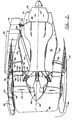
- FIG. 1 there is shown a partial cross-sectional drawing of an exemplary high-bypass ratio gas turbine engine 10 having a core engine portion indicated at 12 and a stator or fan portion indicated at 14.
- the core or engine portion 12 may be referred to as the rotor module.
- the rotor module or core engine 12 includes an intermediate pressure compressor or booster stage 16, a high pressure compressor stage 18, a combustor stage 20, a high pressure turbine stage 21, and a low pressure turbine stage 22 all aligned on an engine centerline 23.
- the core engine 12 further includes fan blades 24 and the spinner assembly 28.
- the fan portion 14 comprises fan cowling 27 and fan casing 26.
- the fan cowling 27 surrounds the fan casing 26 and radially encloses the fan portion of the engine 10.
- the fan spinner assembly 28 located forward of the fan blades 24 connects to a rotor assembly 38 (shown in FIG. 2), rotor assembly 38 being a part of the core engine 12.
- rotor assembly 38 To the aft of fan blades 24 is located a plurality of circumferentially spaced outlet guide vanes or fan frame struts 30 which are a part of the fan portion 14.
- the outlet guide vanes 30 connect the engine core 12 to the fan portion of the engine 10 and provide structural support.
- primary nozzle 33 which includes an outer member 34 and an inner member 35.
- a fan shaft 37 driven by turbine stage 22 extends through the engine and is coupled in driving relationship with booster stage 16. Fan shaft 37 turns fan blades 24 via fan rotor assembly 38 (shown in FIG. 2).
- the forward module includes the fan case 26, structural outlet guide vanes 30, fan spinner assembly 28, fan blades 24, along with fan rotor 38, booster stage 16 and the forward portion of shaft 37.
- FIG. 2 a simplified schematic illustration of the present invention's engine assembly 10, which is similar to FIG. 1, shows an inlet 40 and fan cowling 27 located at the extreme front of the engine 10, the circumferential shape of the inlet forming an air passage by which air can enter the engine.
- Fan case 26 To the aft of inlet 40 is fan case 26 which may be connected to fan cowling 27. Fan case 26 surrounds the fan blades 24 which are located radially inward therefrom.
- To the aft of fan blades 24 lie the fan outlet guide vanes (OGV's) 30 whose distal end portions in the outward radial direction are connected to fan casing 26.
- the front engine mount 42 connects to the wing pylon 44 which is attached to aircraft wing 46.
- Broken line 48 of FIG. 2 indicates the outer portion of engine 10 and includes the inlet 40, fan casing 26 and fan outlet guide vanes 30.
- each fan outlet guide vane 30 is attached to fan outlet guide vane support member 50 and by means of bolts 52.
- support member 50 comprises the aforementioned mid ring for connecting the vane frame to the hub frame which extends through booster casing 54.
- the vane frame indicated at 100, includes the vanes 30 and their inner and outer shrouds 102 and 104.
- the core or hub frame comprises a plurality of struts which extend through the airflow path in casing 54 and terminate at the mid ring connection. In the mid ring area, the walls of the struts flare into flat panels attached to a forward mid ring bulkhead or panel 106 and an aft mid ring bulkhead or panel 108.
- a D-duct type thrust reverser 56 which includes a fan portion 58, a core portion 60 and links 62.
- the links 62 extend circumferentially around core portion 60.
- thrust link 64 Located radially inward from core portion 60 of thrust reverser 56 is thrust link 64 which is attached at one end to pylon 44 at location 66, location 66 being to the aft of thrust reverser 56.
- the other end of thrust link 64 is connected to fan frame 54 by means of brackets (not shown) which extend circumferentially around booster case 54.
- To the aft of location 66 is rear engine mount 68 which connects pylon 44 to a frame 31 on core engine 12.
- the inner portion 72 of the engine 10 may be defined as that portion of the engine extending from the spinner assembly 28 to the primary nozzle 33 which is located radially inward of the thrust reverser 56.
- the inner portion of the engine does not include the fan outlet guide vanes 30 which have been defined to be a part of the outer portion of the engine as they are inside broken line 48 of FIG. 2.
- FIG. 3 is an enlarged, partial cross-sectional illustration of the fan blade and OGV attachment portion of the present invention and shows fan blade 24 connected to blade platform 74.
- the blades 24 are secured to rotor assembly 38 by means of anti-clank spring 76.
- Aft spinner 78 is connected to rotor assembly 38 by means of bolt 80 and forward spinner 82 is connected to aft spinner 78 by means of bolt 84.
- Pin 86 connects the blade platform 74 to rotor assembly 38.
- Acoustic panels 92 are connected to the booster casing 54 by means of a tongue and groove slip joint 94.
- the acoustic panels are also connected to support 50 by bolts 96.
- the fan outlet guide vanes 30 are connected to support 50 by bolts 52 and 98.
- FIG. 4 there is shown an enlarged and more detailed view of mid ring 50 viewed in a tangential direction.
- the forward panel 106 and aft panel 108 each have radially inner flanges 110 and 112, respectively, and radially outer flanges 114, and 116, respectively.
- the radially inner flanges 110 and 112 are cast, molded, or machined to mate with respective ones of the forward and aft bulkheads 118 and 120.
- the flanges 110 and 112 are attached to the bulkheads 118 and 120 by electron beam welding.
- the radially outer flanges 114 and 116 are releasably attached to the inner shroud ring 102 of the vane frame by means of a plurality of circumferentially spaced bolts 122.
- the shroud ring 102 includes forward and aft radially inwardly extending flanges 124 and 126 having a plurality of circumferentially spaced apertures 128 for receiving the bolts 122.
- the bolts 122 are threaded into captive nuts 130A and 130B which are attached to the inside surface of flange 114 and flange 126, respectively.
- the connection between the mid ring 50 and vane frame shroud 102 is designed to provide an engine quick change joint.
- the joint is required to have no motion or yielding under limit loads and no complete failure under ultimate load, i.e., a blade out at take-off. Under these conditions, there is a high radially load transmitted across the mid ring to vane frame joint. To resist such loading, the joint must not slip. However, it has been shown that friction alone in a conventional flat face lap joint is not sufficient to carry such high radial loads without slipping.
- the present invention overcomes this slipping problem by incorporating a tongue and groove shear joint connection in which the flange 114 and the flange 116 each include a protruding tongue indicated at 132A and 132B, respectively, with each tongue fitting into a corresponding groove 134A and 134B in flanges 124 and 126, respectively.
- a tongue and groove shear joint connection in which the flange 114 and the flange 116 each include a protruding tongue indicated at 132A and 132B, respectively, with each tongue fitting into a corresponding groove 134A and 134B in flanges 124 and 126, respectively.
- the tongue 132 and groove 134 are each formed with beveled video.
- the sides are beveled at 45°.
- This arrangement forms an angle wedge which is self aligning when the flanges are attached one to the other.
- the size and weight of the engine modules involved in this flange connection would make a conventional rabbeted joint extremely difficult to assemble or disassemble.
- the wedge shaped tongue and groove joint provides for ease of assembly and also assists in aligning the joint as the bolts 122 are tightened.
- FIG. 4 also illustrates the radial positioning of the joint at flange 114 and the joint at flange 116. It will be noted that the flange 114 is positioned at a radius which is less than the radius of the inner end of flange 126. This arrangement allows the mid ring to be slid axially aft such that the flange 114 passes under the flange 126 to allow the core engine to be removed from the vane frame assembly. Referring briefly to FIG. 5, there is shown an axial view of an alternate embodiment of the mid ring 50 and vane frame shroud 102 in which the edges of the flange 114 and flange 126 are scalloped such that the peaks of flange 114 fit within the valleys of flange 126. This alternate embodiment allows the flange 114 to pass through the space occupied by flange 126 again permitting the mid ring to slide axially aft out of the vane frame assembly.
- the panels are interconnected by a plurality of circumferentially spaced stiffeners or shear panels 136.
- Each of the stiffeners 136 comprises a first flange or stringer 138 extending diagonally from flange 112 to flange 114.
- a second flange or stringer 140 extends diagonally from flange 110 to flange 116.
- the stringers 138 and 140 form an X-shaped frame structure providing stabilizing stiffness between the forward panel 106 and aft panel 108.
- the panels 142 and 144 are desirably cast or molded in combination with the stringers 138 and 140 to form a composite structure. More particularly, in the manufacturing process, the forward and aft panels 106 and 108 may be cast integrally with the stiffeners 136 to form a circumferential segment which may be joined with additional circumferential segments to form the complete annular mid ring 50. In addition, it may be desirable to add support panels in the triangular space radially inward of the stringer 140 and stringer 138. It will be noted that the diagonal stringers 138 and 140 form an X-shaped structure that provides stability to the stiffeners which is essentially comprised of the support panels 142 and 144.
- the diagonal stringers 138 and 140 provide axial support to the separable joints at flanges 114 and 116. Compliance between these separable joints is accomplished by the absence of material in the space above the stringers 138 and 140 adjacent the radial inward face of shroud 102. The absence of material in space above the diagonal stringers 138 and 140 allows sufficient flexibility of the forward and aft panels 106 and 108 so that they may flex in the axial direction to accommodate a tolerance stack-up between the separable connections at flanges 114 and 116. Additional flexibility of the panel in the axial direction may also be accommodated by eliminating the shear or support panel below the stiffeners 138 and 140.
- FIG. 6 there is shown a perspective view of one of the circumferential segments of mid ring 50.
- the forward and aft panels 106, 108 and their associated flanges 114, 116 are shown on a schematic end of this view.
- What is more clearly shown in FIG. 6 is the addition of circumferential webs 146 and 148 in each space between the stiffeners 136.
- the webs 146 and 148 are angularly oriented such that one side of each web is attached to an edge of a stringer 140 and another aide of each web is attached to the aft flange 116.
- the webs 146 and 148 thus provide support in the circumferential direction to minimize the tendency of the stiffeners 136 to buckle or vibrate in a circumferential direction.
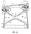
- FIG. 7 is an axial view of a section of a gas turbine engine showing the struts which extend from the inner flowpath wall 150 to the mid ring 50.
- the struts are hollow having opposite sidewalls 152A and 152B which terminate at about the point at which the inner stiffeners 136 begin within a mid ring 50.
- the outer stiffeners 136 occurring at each end of each mid ring segment are not aligned with struts but are rather aligned on a radial line extending from the engine axis.
- FIG. 8 illustrates an alternate form of stiffener structure in which the stiffener is primarily a shear panel 160 surrounded by a diagonal stringer 162 and an axially oriented stringer 164.
- the shear panel 160 is connected to the top of the strut wall 166 along the line 168 by electron beam welding.
- the hub frame remains a one piece fabricated structure with a hub mid ring 50 welded to the hub casting.
- the diagonal stringer 162 extends from the forward lower flange 110 to an intersection with the inner web 146 near the separable joint at flange 116. In the extreme, the flange 162 could be formed as a complete 360° shell within the mid ring 50.
- the diagonal connection formed by flange or stringer 162 provides axial strength to the mid ring 50. Since the panel 160 does not extend to the forward panel 106, the hub portion of the separable joint at flange 114 is relatively free to flex forward or aft allowing the hub mid ring flanges 114 and 116 to be compliant, in the axial direction, with the vane frame forward and aft flanges 124 and 126.
- the apertures 170 and 172 are provided to accommodate electron beam welding of the joints between flanges 110, 118, and 112, 120.
- the diagonal stringers provide axial support to the separable joints at flanges 114 and 116.
- the diagonal stringers also provide stiffness to the shear or support panels connecting the forward and aft panels 106 and 108 to improve stability of the panels and stability of the overall hub frame structure. Compliance between the flange joints at flanges 114 and 116 is improved by the absence of material in the space above the diagonal stringers. This allows sufficient flexibility between the flanges 114, 116, 124, and 126 to permit flex or motion in the axial direction to accommodate any tolerance stack-up during manufacture.
- the hub frame mid ring 50 is cast separately in one or more pieces and a central portion of the hub frame is cast in one piece.
- the smaller radius circumferential weld locations at flanges 110 and 112 allow a smaller and more manageable hub casting.
- movement of the welds to smaller radius positions allows the complete mid ring sections all to be cast in a one piece ring above the circumferential welds at flanges 110 and 112.
- the tongue and groove shear joints also provide much nigher resistance to joint slippage than conventional joints for the given size and number of bolted connections.
- the tongue and grove joint is also self aligning due to the wedge shaped faces on the tongue and groove joints thereby facilitating concentric assembly of very large engine modules.
- Circumferential variation in the type of joint i.e., using the tongue and groove in certain locations and an overlapping lighter weight joint in other locations results in a lighter weight constructions of the mid ring assembly.
Landscapes
- Engineering & Computer Science (AREA)
- Chemical & Material Sciences (AREA)
- Combustion & Propulsion (AREA)
- Mechanical Engineering (AREA)
- General Engineering & Computer Science (AREA)
- Aviation & Aerospace Engineering (AREA)
- Turbine Rotor Nozzle Sealing (AREA)
- Structures Of Non-Positive Displacement Pumps (AREA)
Applications Claiming Priority (4)
| Application Number | Priority Date | Filing Date | Title |
|---|---|---|---|
| US785365 | 1985-10-07 | ||
| US70826391A | 1991-05-28 | 1991-05-28 | |
| US708263 | 1991-05-28 | ||
| US07/785,365 US5222360A (en) | 1991-10-30 | 1991-10-30 | Apparatus for removably attaching a core frame to a vane frame with a stable mid ring |
Publications (3)
| Publication Number | Publication Date |
|---|---|
| EP0516389A2 true EP0516389A2 (fr) | 1992-12-02 |
| EP0516389A3 EP0516389A3 (en) | 1993-08-25 |
| EP0516389B1 EP0516389B1 (fr) | 1997-08-06 |
Family
ID=27108045
Family Applications (1)
| Application Number | Title | Priority Date | Filing Date |
|---|---|---|---|
| EP92304786A Expired - Lifetime EP0516389B1 (fr) | 1991-05-28 | 1992-05-27 | Appareil pour la connexion amovible d'une structure centrale à une couronne d'ailettes de guidage à l'aide d'un anneau intermédiaire |
Country Status (3)
| Country | Link |
|---|---|
| EP (1) | EP0516389B1 (fr) |
| JP (1) | JPH06105048B2 (fr) |
| DE (1) | DE69221389D1 (fr) |
Cited By (6)
| Publication number | Priority date | Publication date | Assignee | Title |
|---|---|---|---|---|
| FR2887850A1 (fr) * | 2005-06-29 | 2007-01-05 | Airbus France Sas | Dispositif d'accrochage d'un moteur interpose entre une voilure d'aeronef et ledit moteur |
| US7635957B2 (en) | 2003-09-04 | 2009-12-22 | Koninklijke Philips Electronics, N.V. | LED temperature-dependent power supply system and method |
| US9470243B2 (en) | 2011-03-09 | 2016-10-18 | Ihi Corporation | Guide vane attachment structure and fan |
| US10443447B2 (en) | 2016-03-14 | 2019-10-15 | General Electric Company | Doubler attachment system |
| CN115387906A (zh) * | 2022-05-12 | 2022-11-25 | 中国航发四川燃气涡轮研究院 | 低进口轮毂比发动机的进气承力框架连接结构及装配方法 |
| CN115716536A (zh) * | 2022-10-25 | 2023-02-28 | 中国航发沈阳发动机研究所 | 一种薄壁高强斜支板承力框架结构 |
Families Citing this family (4)
| Publication number | Priority date | Publication date | Assignee | Title |
|---|---|---|---|---|
| JPH08319865A (ja) * | 1995-05-26 | 1996-12-03 | Mitsubishi Motors Corp | 筒内噴射式内燃機関における燃料噴射制御装置 |
| FR2872485B1 (fr) * | 2004-07-05 | 2006-09-15 | Snecma Moteurs Sa | Raidisseur pour compresseur basse pression d'un moteur d'aeronef |
| JP5962887B2 (ja) | 2012-02-02 | 2016-08-03 | 株式会社Ihi | 翼の連結部構造及びこれを用いたジェットエンジン |
| JP6082193B2 (ja) | 2012-06-20 | 2017-02-15 | 株式会社Ihi | 翼の連結部構造及びこれを用いたジェットエンジン |
Citations (5)
| Publication number | Priority date | Publication date | Assignee | Title |
|---|---|---|---|---|
| DE1626119C3 (de) * | 1966-10-06 | 1974-08-15 | Secretary Of State For Defence Of The United Kingdom Of Great Britain And Northern Ireland, London | Lagerabstützung |
| FR2219313A1 (fr) * | 1973-02-26 | 1974-09-20 | Avco Corp | |
| GB2192233A (en) * | 1986-07-02 | 1988-01-06 | Rolls Royce Plc | Load transfer structure |
| US4785625A (en) * | 1987-04-03 | 1988-11-22 | United Technologies Corporation | Ducted fan gas turbine power plant mounting |
| GB2219046A (en) * | 1988-05-13 | 1989-11-29 | United Technologies Corp | Disassembly of a modular fan gas turbine engine |
-
1992
- 1992-05-19 JP JP4125221A patent/JPH06105048B2/ja not_active Expired - Fee Related
- 1992-05-27 EP EP92304786A patent/EP0516389B1/fr not_active Expired - Lifetime
- 1992-05-27 DE DE69221389T patent/DE69221389D1/de not_active Expired - Lifetime
Patent Citations (5)
| Publication number | Priority date | Publication date | Assignee | Title |
|---|---|---|---|---|
| DE1626119C3 (de) * | 1966-10-06 | 1974-08-15 | Secretary Of State For Defence Of The United Kingdom Of Great Britain And Northern Ireland, London | Lagerabstützung |
| FR2219313A1 (fr) * | 1973-02-26 | 1974-09-20 | Avco Corp | |
| GB2192233A (en) * | 1986-07-02 | 1988-01-06 | Rolls Royce Plc | Load transfer structure |
| US4785625A (en) * | 1987-04-03 | 1988-11-22 | United Technologies Corporation | Ducted fan gas turbine power plant mounting |
| GB2219046A (en) * | 1988-05-13 | 1989-11-29 | United Technologies Corp | Disassembly of a modular fan gas turbine engine |
Cited By (8)
| Publication number | Priority date | Publication date | Assignee | Title |
|---|---|---|---|---|
| US7635957B2 (en) | 2003-09-04 | 2009-12-22 | Koninklijke Philips Electronics, N.V. | LED temperature-dependent power supply system and method |
| FR2887850A1 (fr) * | 2005-06-29 | 2007-01-05 | Airbus France Sas | Dispositif d'accrochage d'un moteur interpose entre une voilure d'aeronef et ledit moteur |
| US9470243B2 (en) | 2011-03-09 | 2016-10-18 | Ihi Corporation | Guide vane attachment structure and fan |
| US10443447B2 (en) | 2016-03-14 | 2019-10-15 | General Electric Company | Doubler attachment system |
| CN115387906A (zh) * | 2022-05-12 | 2022-11-25 | 中国航发四川燃气涡轮研究院 | 低进口轮毂比发动机的进气承力框架连接结构及装配方法 |
| CN115387906B (zh) * | 2022-05-12 | 2024-04-16 | 中国航发四川燃气涡轮研究院 | 低进口轮毂比发动机的进气承力框架连接结构及装配方法 |
| CN115716536A (zh) * | 2022-10-25 | 2023-02-28 | 中国航发沈阳发动机研究所 | 一种薄壁高强斜支板承力框架结构 |
| CN115716536B (zh) * | 2022-10-25 | 2023-07-21 | 中国航发沈阳发动机研究所 | 一种薄壁高强斜支板承力框架结构 |
Also Published As
| Publication number | Publication date |
|---|---|
| JPH05149148A (ja) | 1993-06-15 |
| DE69221389D1 (de) | 1997-09-11 |
| EP0516389B1 (fr) | 1997-08-06 |
| EP0516389A3 (en) | 1993-08-25 |
| JPH06105048B2 (ja) | 1994-12-21 |
Similar Documents
| Publication | Publication Date | Title |
|---|---|---|
| US5222360A (en) | Apparatus for removably attaching a core frame to a vane frame with a stable mid ring | |
| US5224341A (en) | Separable fan strut for a gas turbofan powerplant | |
| EP1857639B1 (fr) | Chassis de soufflante | |
| US7802962B2 (en) | Bearing support structure and a gas turbine engine comprising the bearing support structure | |
| US7739866B2 (en) | Turbofan case and method of making | |
| US6672833B2 (en) | Gas turbine engine frame flowpath liner support | |
| US7266941B2 (en) | Turbofan case and method of making | |
| US9481470B2 (en) | Intermediate structure for independently de-mountable propulsion components | |
| US4249859A (en) | Preloaded engine inlet shroud | |
| EP1122443B1 (fr) | Montage d'un rotor | |
| US5307623A (en) | Apparatus and method for the diassembly of an ultra high bypass engine | |
| EP0516389B1 (fr) | Appareil pour la connexion amovible d'une structure centrale à une couronne d'ailettes de guidage à l'aide d'un anneau intermédiaire | |
| US10443447B2 (en) | Doubler attachment system | |
| US20150337687A1 (en) | Split cast vane fairing | |
| US20050008486A1 (en) | Exit stator mounting | |
| CN110130999B (zh) | 用于轴流式涡轮发动机的结构壳体 | |
| JPH03141829A (ja) | ファン/カウル一体化の超高バイパス比エンジン及びその輸送/取外し | |
| EP0677145B1 (fr) | Montant de ventilateur demontable pour groupe motopropulseur d'un turboreacteur a double flux a gaz | |
| EP3441562A1 (fr) | Appareil à disque de soufflante | |
| US20190300190A1 (en) | Turbine engine | |
| US20140161605A1 (en) | Gas turbine structure |
Legal Events
| Date | Code | Title | Description |
|---|---|---|---|
| PUAI | Public reference made under article 153(3) epc to a published international application that has entered the european phase |
Free format text: ORIGINAL CODE: 0009012 |
|
| AK | Designated contracting states |
Kind code of ref document: A2 Designated state(s): DE FR GB IT |
|
| PUAL | Search report despatched |
Free format text: ORIGINAL CODE: 0009013 |
|
| AK | Designated contracting states |
Kind code of ref document: A3 Designated state(s): DE FR GB IT |
|
| 17P | Request for examination filed |
Effective date: 19940131 |
|
| 17Q | First examination report despatched |
Effective date: 19950320 |
|
| GRAG | Despatch of communication of intention to grant |
Free format text: ORIGINAL CODE: EPIDOS AGRA |
|
| GRAH | Despatch of communication of intention to grant a patent |
Free format text: ORIGINAL CODE: EPIDOS IGRA |
|
| GRAH | Despatch of communication of intention to grant a patent |
Free format text: ORIGINAL CODE: EPIDOS IGRA |
|
| GRAH | Despatch of communication of intention to grant a patent |
Free format text: ORIGINAL CODE: EPIDOS IGRA |
|
| GRAH | Despatch of communication of intention to grant a patent |
Free format text: ORIGINAL CODE: EPIDOS IGRA |
|
| GRAH | Despatch of communication of intention to grant a patent |
Free format text: ORIGINAL CODE: EPIDOS IGRA |
|
| GRAA | (expected) grant |
Free format text: ORIGINAL CODE: 0009210 |
|
| AK | Designated contracting states |
Kind code of ref document: B1 Designated state(s): DE FR GB IT |
|
| PG25 | Lapsed in a contracting state [announced via postgrant information from national office to epo] |
Ref country code: IT Free format text: LAPSE BECAUSE OF FAILURE TO SUBMIT A TRANSLATION OF THE DESCRIPTION OR TO PAY THE FEE WITHIN THE PRESCRIBED TIME-LIMIT;WARNING: LAPSES OF ITALIAN PATENTS WITH EFFECTIVE DATE BEFORE 2007 MAY HAVE OCCURRED AT ANY TIME BEFORE 2007. THE CORRECT EFFECTIVE DATE MAY BE DIFFERENT FROM THE ONE RECORDED. Effective date: 19970806 |
|
| ET | Fr: translation filed | ||
| REF | Corresponds to: |
Ref document number: 69221389 Country of ref document: DE Date of ref document: 19970911 |
|
| PG25 | Lapsed in a contracting state [announced via postgrant information from national office to epo] |
Ref country code: DE Effective date: 19971107 |
|
| PLBE | No opposition filed within time limit |
Free format text: ORIGINAL CODE: 0009261 |
|
| STAA | Information on the status of an ep patent application or granted ep patent |
Free format text: STATUS: NO OPPOSITION FILED WITHIN TIME LIMIT |
|
| 26N | No opposition filed | ||
| REG | Reference to a national code |
Ref country code: GB Ref legal event code: IF02 |
|
| PGFP | Annual fee paid to national office [announced via postgrant information from national office to epo] |
Ref country code: FR Payment date: 20060517 Year of fee payment: 15 |
|
| PGFP | Annual fee paid to national office [announced via postgrant information from national office to epo] |
Ref country code: GB Payment date: 20060525 Year of fee payment: 15 |
|
| GBPC | Gb: european patent ceased through non-payment of renewal fee |
Effective date: 20070527 |
|
| REG | Reference to a national code |
Ref country code: FR Ref legal event code: ST Effective date: 20080131 |
|
| PG25 | Lapsed in a contracting state [announced via postgrant information from national office to epo] |
Ref country code: GB Free format text: LAPSE BECAUSE OF NON-PAYMENT OF DUE FEES Effective date: 20070527 |
|
| PG25 | Lapsed in a contracting state [announced via postgrant information from national office to epo] |
Ref country code: FR Free format text: LAPSE BECAUSE OF NON-PAYMENT OF DUE FEES Effective date: 20070531 |