EP0516059A1 - Traffic warning system - Google Patents
Traffic warning system Download PDFInfo
- Publication number
- EP0516059A1 EP0516059A1 EP92108871A EP92108871A EP0516059A1 EP 0516059 A1 EP0516059 A1 EP 0516059A1 EP 92108871 A EP92108871 A EP 92108871A EP 92108871 A EP92108871 A EP 92108871A EP 0516059 A1 EP0516059 A1 EP 0516059A1
- Authority
- EP
- European Patent Office
- Prior art keywords
- warning system
- traffic warning
- light
- light sources
- sensor
- Prior art date
- Legal status (The legal status is an assumption and is not a legal conclusion. Google has not performed a legal analysis and makes no representation as to the accuracy of the status listed.)
- Granted
Links
Images
Classifications
-
- B—PERFORMING OPERATIONS; TRANSPORTING
- B60—VEHICLES IN GENERAL
- B60Q—ARRANGEMENT OF SIGNALLING OR LIGHTING DEVICES, THE MOUNTING OR SUPPORTING THEREOF OR CIRCUITS THEREFOR, FOR VEHICLES IN GENERAL
- B60Q7/00—Arrangement or adaptation of portable emergency signal devices on vehicles
-
- G—PHYSICS
- G09—EDUCATION; CRYPTOGRAPHY; DISPLAY; ADVERTISING; SEALS
- G09F—DISPLAYING; ADVERTISING; SIGNS; LABELS OR NAME-PLATES; SEALS
- G09F27/00—Combined visual and audible advertising or displaying, e.g. for public address
- G09F27/007—Displays with power supply provided by solar cells or photocells
Landscapes
- Engineering & Computer Science (AREA)
- Mechanical Engineering (AREA)
- Life Sciences & Earth Sciences (AREA)
- Sustainable Development (AREA)
- Physics & Mathematics (AREA)
- General Physics & Mathematics (AREA)
- Theoretical Computer Science (AREA)
- Road Signs Or Road Markings (AREA)
- Traffic Control Systems (AREA)
- Alarm Systems (AREA)
- Photovoltaic Devices (AREA)
Abstract
Description
Die Erfindung betrifft ein Verkehrswarnsystem nach dem Oberbegriff des Anspruchs 1.The invention relates to a traffic warning system according to the preamble of
Zum Absichern besonders gefährdeter Straßenabschnitte, wie z.B. Baustellen, Tunneleinfahrten, Engstellen etc. werden tragbare oder stationäre Verkehrswarnsysteme verwendet, die häufig zusätzlich zu den üblichen Verkehrsschildern angebracht werden und aufgrund ihrer erhöhten Signalwirkung die Verkehrsteilnehmer, insbesondere Kraftfahrer, bei schlechtem Wetter rechtzeitig über bevorstehende Gefahrenstellen unterrichten.To secure particularly vulnerable road sections, e.g. Construction sites, tunnel entrances, bottlenecks, etc., use portable or stationary traffic warning systems, which are often installed in addition to the usual traffic signs and, due to their increased signal effect, inform road users, especially drivers, in good time of impending danger spots in bad weather.
Aus der DE 40 01 980 A1 ist ein Markierungsnagel für Fahrbahnen bekannt. Die nach oben weisende Fläche des Nagelkopfes ist mit Solarzellen versehen und weist einen Helligkeitssensor auf sowie mindestens eine Leuchtdiode, wobei die die Leuchtdiode umgebende Fläche des Nagelkopfes mit einem reflektierenden Material beschichtet ist; im Nagelschaft ist ein Akkumulator vorgesehen, der über die Solarzelle bei Tageslichteinfall geladen wird und bei Dunkelheit mit dem in ihm gespeicherten elektrischen Strom die Leuchtdiode beaufschlagt.From DE 40 01 980 A1 a marking nail for lanes is known. The upward-facing surface of the nail head is provided with solar cells and has a brightness sensor and at least one light-emitting diode, the surface of the nail head surrounding the light-emitting diode being coated with a reflective material; An accumulator is provided in the nail shaft, which is charged via the solar cell in the daylight and which acts on the light-emitting diode in the dark with the electrical current stored in it.
Der Nagelkopf weist eine im wesentlichen flache Form auf mit einer nur wenig oberhalb der Fahrbahnfläche liegenden Oberfläche, so daß nur eine geringe Seitenfläche für die Anordnung von Leuchtdioden zur Verfügung steht, über die ein Kraftfahrer über größere Entfernungen gewarnt werden soll. Ferner muß damit gerechnet werden, daß an Tagen mit geringem Sonneneinfall aufgrund größerer Bewölkungsdichte nur eine geringe Strommenge im Akkumulator gespeichert wird, so daß schon nach relativ kurzer Zeit für die Beaufschlagung der Leuchtdioden kein Strom mehr zur Verfügung steht.The nail head has an essentially flat shape with a surface lying just above the road surface, so that only a small side surface is available for the arrangement of light-emitting diodes, by means of which a driver is to be warned of greater distances. Furthermore, it must be expected that on days with little sunshine due to greater cloud density only a small amount of electricity will be stored in the accumulator, so that after a relatively short time for the application the light emitting diodes are no longer available.
Aus FR 21 19 328 ist ein Warndreieck bekannt, dessen Schenkel als Reflektoren ausgebildet sind, vor denen blinkende Lichtquellen verteilt angeordnet sind. Die Schaltung, die die Lichtquellen entsprechend der Blinkfrequenz beaufschlagt, ist als astabiler Multivibrator mit zwei Transistoren ausgeführt. Bei einem rechnerisch ermittelten Taktverhältnis von 1:2 (50 %) und einer Betriebsspannung von 9 Volt für die Ansteuerung der beiden Transistoren ergibt sich ein mittlerer Dauerstrom von fast 6 mA und für den Betrieb mit den Leuchtguellen von mehr als 200 mA.A warning triangle is known from FR 21 19 328, the legs of which are designed as reflectors, in front of which flashing light sources are arranged in a distributed manner. The circuit that applies the light sources according to the flashing frequency is designed as an astable multivibrator with two transistors. With a calculated clock ratio of 1: 2 (50%) and an operating voltage of 9 volts for the control of the two transistors, the average continuous current is almost 6 mA and for operation with the light sources of more than 200 mA.
Der vorliegenden Erfindung liegt die Aufgabe zugrunde, ein Verkehrswarnsystem zu schaffen, das unabhängig von den Witterungsbedingungen die Verkehrsteilnehmer über eine große Entfernung über eine bevorstehende Gefahrenstelle informiert, das einen außerordentlich geringen Strombedarf aufweist und das billig in der Herstellung ist.The object of the present invention is to create a traffic warning system which, regardless of the weather conditions, informs road users over a long distance of an impending danger point, which has an extremely low power requirement and which is inexpensive to manufacture.
Dies wird erfindungsgemäß mit dem im Anspruch 1 gekennzeichneten Verkehrswarnsystem erreicht. In den Unteransprüchen sind vorteilhafte Ausgestaltungen der Erfindung wiedergegeben.This is achieved according to the invention with the traffic warning system characterized in
Das erfindungsgemäße Verkehrswarnsystem weist den Vorteil einer ungewöhnlich hohen Lichtintensität im Blinkbetrieb auf, wodurch Sichtreichweiten von über 1000 m erzielt werden bei gleichzeitg extrem geringem Strombedarf. Wie Versuche gezeigt haben, kann das erfindungsgemäße Verkehrswarnsystem mit einem mittleren Gesamtstrombedarf von weniger als 4 mA betrieben werden. Damit ist bei der Batterieversion eine Betriebsdauer im Tag/Nacht-Wechselbetrieb ohne Batteriewechsel von drei Jahren möglich.The traffic warning system according to the invention has the advantage of an unusually high light intensity in the blinking mode, whereby visibility ranges of over 1000 m are achieved with an extremely low power requirement at the same time. As tests have shown, the traffic warning system according to the invention can be operated with an average total current requirement of less than 4 mA. This means that the battery version can run for three years in day / night alternation without changing the battery.
Dieser extrem geringe Strombedarf wird im wesentlichen durch die sehr kurzen Stromimpulse von weniger als 100 ms, vorzugsweise weniger als 50 ms erreicht, mit denen erfindungsgemäß die Lichtquellen beaufschlagt werden.This extremely low current requirement is essentially achieved by the very short current pulses of less than 100 ms, preferably less than 50 ms, which are applied to the light sources according to the invention.
Dabei wird erfindungsgemäß ein physiologischer Effekt genutzt. Bei unmittelbarer Belichtung verengt sich die Pupille des Auges. Wie Messungen ergeben haben, ist die Reaktionszeit der Pupille sehr kurz, das heißt eine Verengung der Pupille tritt beim Menschen normalerweise bereits nach einer Belichtungsdauer von 30 ms ein. Wenn sich die Pupille verengt, fällt weniger Licht auf die Netzhaut. Das heißt, die Netzhaut wird zunächst ca. 30 ms maximal erregt, worauf der Lichteinfall durch die sich verengende Pupille und damit die Netzhauterregung abnimmt. Mit anderen Worten, ein Lichtimpuls hat für das Auge nur für eine Dauer von ca. 30 ms die größte Auffälligkeit, dann nimmt seine Auffälligkeit bereits ab.A physiological effect is used according to the invention. With direct exposure, the pupil of the eye narrows. As measurements have shown, the response time of the pupil is very short, which means that a narrowing of the pupil usually occurs after an exposure time of 30 ms in humans. When the pupil narrows, less light falls on the retina. This means that the retina is initially excited to a maximum of about 30 ms, after which the incidence of light decreases due to the narrowing pupil and thus the excitation of the retina. In other words, a light pulse has the greatest conspicuousness for the eye only for a period of approx. 30 ms, then its conspicuousness already decreases.
Die Oberfläche, an der der wenigstens eine Reflektor des erfindungsgemäßen Verkehrswarnsystems angeordnet ist, wird vorzugsweise durch die Oberfläche eines Gehäuses gebildet. Die Lichtquellen des erfindungsgemäßen Verkehrswarnsystems sind vorzugsweise über die gesamte mit dem Reflektor versehene Oberfläche verteilt. Dabei weisen sie eine derart hohe Lichtstärke auf, daß ein Überstrahlen des Reflektors erreicht wird.The surface on which the at least one reflector of the traffic warning system according to the invention is arranged is preferably formed by the surface of a housing. The light sources of the traffic warning system according to the invention are preferably distributed over the entire surface provided with the reflector. They have such a high light intensity that the reflector is outshined.
Vorzugsweise sind die Lichtquellen Leuchtdioden, die eine Lichtstärke von mehr als 500 mcd, vorzugsweise mehr als 1400 mcd aufweisen. Die Stromstärke beträgt während der Impulspausen im Blinkbetrieb weniger als 500 µA, vorzugsweise weniger als 100 µA. Während des Zeiraums, in dem die Umfeldleuchtdichte oberhalb des vorgegebenen Schwellwerts liegt, wird die Stromstärke auf einen Wert kleiner als 100 µA, vorzugsweise kleiner 11 µA begrenzt.The light sources are preferably light-emitting diodes which have a light intensity of more than 500 mcd, preferably more than 1400 mcd. The current strength is less than 500 μA, preferably less than 100 μA, during the pulse pauses in the blinking operation. During the time period in which the surrounding luminance is above the specified threshold lies, the current intensity is limited to a value less than 100 µA, preferably less than 11 µA.
Als Stromquelle kommt eine Trockenbatterie oder eine Solarzelle in Frage, der ein Akkumulator nachgeschaltet ist.A dry battery or a solar cell can be used as the power source, followed by an accumulator.
Die elektronische Schaltung umfaßt vorteilhafterweise einen Taktgenerator, der aus einem NAND-Schmitt-Trigger mit R/C-Schaltglied besteht, wobei einer der Eingänge des Schmitt-Triggers durch den Sensor ansteuerbar ist. Der erste Schmitt-Trigger ist mit einem zweiten Schmitt-Trigger verbunden, welcher das vom Taktgenerator gelieferte Signal in der extrem kurzen Impulsdauer von vorzugsweise weniger als 50 ms umwandelt. Ein Leistungsteil verstärkt das umgewandelte Signal. Seine Stromstärke ist auf einen vorgegebenen Wert von vorzugsweise höchstens 200 mA begrenzt.The electronic circuit advantageously comprises a clock generator, which consists of a NAND-Schmitt trigger with an R / C switching element, one of the inputs of the Schmitt trigger being controllable by the sensor. The first Schmitt trigger is connected to a second Schmitt trigger, which converts the signal supplied by the clock generator in the extremely short pulse duration of preferably less than 50 ms. A power section amplifies the converted signal. Its current strength is limited to a predetermined value of preferably at most 200 mA.
Im Falle eines Verkehrswarnsystems mit einer Trockenbatterie besteht der Sensor vorteilhafterweise aus einem Phototransistor, der mit einem Widerstand verbunden ist, dessen Spannungsabfall den Taktgenerator ansteuert; im Falle eines Verkehrswarnsystems mit einer Solarzelle als Stromquelle dient diese vorteilhafterweise zugleich als Sensor.In the case of a traffic warning system with a dry battery, the sensor advantageously consists of a phototransistor, which is connected to a resistor, the voltage drop of which drives the clock generator; in the case of a traffic warning system with a solar cell as the power source, this advantageously also serves as a sensor.
Durch die Verwendung der sehr hellen Leuchtdioden mit einer Leuchtstärke von vorzugsweise mehr als 1400 mcd und deren großflächige Anordnung über die dem sich nähernden Verkehrsteilnehmer zugewandte Oberfläche mit dem Reflektor wird ein Überstrahlen des Reflektors erreicht, so daß auch bei einem kurzen Betrachtungsabstand das für das menschliche Auge wesentlich auffälligere Blinklicht voll zur Geltung kommt.By using the very bright light-emitting diodes with a luminosity of preferably more than 1400 mcd and their large-area arrangement over the surface facing the approaching road user with the reflector, the reflector is outshone, so that even with a short viewing distance this is for the human eye much more striking flashing light comes into its own.
Im folgenden wird die Erfindung anhand der Zeichnung näher erläutert, in der ein vorteilhaftes Ausführungsbeispiel dargestellt ist. Es zeigen:
- Fig. 1
- eine perspektivische Ansicht eines erfindungsgemäßen Verkehrswarnsystems;
- Fig. 2
- eine Seitenansicht dieses Systems und
- Fig. 3
- ein Blockschaltbild.
- Fig. 1
- a perspective view of a traffic warning system according to the invention;
- Fig. 2
- a side view of this system and
- Fig. 3
- a block diagram.
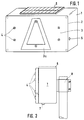
In Fig. 1 ist mit 1 das Gehäuse eines erfindungsgemäßen Verkehrswarnsystems bezeichnet, das als tragbares System ausgestaltet ist, jedoch auch mit einer in Fig. 2 dargestellten Halterung 8 stationär an einem Pfosten befestigt werden kann.In Fig. 1, 1 denotes the housing of a traffic warning system according to the invention, which is designed as a portable system, but can also be fixed to a post with a bracket 8 shown in Fig. 2.
Auf der dem sich nähernden Verkehrsteilnehmer zugewandten Oberfläche 2 des Gehäuses 1 ist ein Reflektor befestigt, der den größten Teil der Oberfläche bedeckt und z.B. aus einer Reflektorfolie 3 einer ersten Farbe, z.B. weiß besteht, sowie aus einer zweiten Reflektorfolie 3a, einer anderen Farbe, z.B. rot. Tagsüber und insbesondere bei Sonnenschein ist dieses Verkehrswarnsystem, das vorteilhafterweise in einer gewissen Höhe über dem Boden angeordnet wird, bereits von weitem für sich nähernde Verkehrsteilnehmer sichtbar.A reflector is attached to the
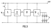
Um auch bei Dunkelheit die gleiche Warnfunktion auszuüben, sind auf der Oberfläche 2 des Gehäuses 1 eine Vielzahl von Leuchtdioden 4 großflächig verteilt, z.B. sechs Leuchtdioden, die in der in Fig. 1 gezeigten Weise angeordnet sein können. Als Leuchtdioden werden solche mit einer Lichtstärke von mehr als 1400 mcd und vorteilhafterweise von 1500 mcd verwendet, da diese in der Lage sind, bei ihrer großflächigen Anordnung gemäß Fig. 1 ein Überstrahlen der auf der Oberfläche 2 des Gehäuses 1 montierten weißen und roten Reflektorfolien 3, 3a zu ermöglichen. Im Inneren des Gehäuses 1 ist eine elektronische Schaltung zur Stromversorgung der Leuchtdioden 4 vorgesehen, deren Blockschaltbild in Fig. 3 schematisch dargestellt ist.In order to carry out the same warning function even in the dark, a large number of light-emitting
Diese Schaltung ist derart ausgelegt, daß sie während des Betriebes sehr wenig Strom aufnimmt, also eine sehr lange Betriebsdauer im Falle eines Verkehrswarnsystems mit Batterie ermöglicht bzw. bei Betrieb mit einer Solarzelle mit einer relativ einfachen Solarzelle auskommt. Zu diesem Zweck weist die elektronische Schaltung einen Taktgenerator 11 mit einer Taktzeit von 0,5 bis 2 s auf, der als NAND-Schmitt-Trigger mit einem R/C-Schaltglied ausgestaltet ist, wobei der eine Eingang des Schmitt-Triggers durch einen Helligkeitssensor 5 angesteuert wird, der bei Tageshelligkeit den Taktgenerator 11 sperrt. Dem Taktgenerator 11, der ein Rechtecksignal liefert, ist eine Impulsformerstufe 12 nachgeschaltet, der das Signal des Taktgenerators 11 über ein zweites R/C-Glied zugeführt wird. Der Impulsformer 12 wird durch einen weiteren NAND-Schmitt-Trigger gebildet, wodurch die fallende Flanke des Rechteckimpulses des ersten Schmitt-Triggers in einen positiven Impuls von z.B. 30 ms umgewandelt wird.This circuit is designed in such a way that it consumes very little current during operation, ie enables a very long operating time in the case of a traffic warning system with a battery or manages with a relatively simple solar cell when operated with a solar cell. For this purpose, the electronic circuit has a
Dieser umgewandelte 30 ms Impuls wird durch ein nachgeschaltetes Leistungsteil 13, z.B. eine NPN-Transistorstufe in Kollektorschaltung verstärkt und über einen in der Emitterleitung liegenden Widerstand auf eine niedrige Stromstärke von z.B. 100 mA begrenzt und dann den Leuchtdioden 4 zugeführt.This converted 30 ms pulse is generated by a downstream power unit 13, e.g. an NPN transistor stage in the collector circuit is amplified and, via a resistor in the emitter line, to a low current of e.g. 100 mA limited and then fed to the
Zur Aktivierung der elektronischen Schaltung ist ein auf die Umfeldleuchtdichte reagierender Sensor 5 vorgesehen, der beim Batteriemodell aus einem Phototransistor besteht, der mit einem Widerstand zusammengeschaltet ist. Der Spannungsabfall am Widerstand steuert in diesem Fall einen Eingang des Taktgenerators an.To activate the electronic circuit, a
Sofern das Verkehrswarnsystem mit einer Solarzelle 6 (Fig. 1) versehen ist, kann diese Solarzelle 6 die Funktion des Sensors 5 übernehmen, indem ein NPN-Schalttransistor hochohmig angesteuert wird, welcher über einen ebenfalls hochohmigen Arbeitswiderstand einen Eingang des Taktgenerators 11 schaltet, wodurch eine Helligkeitserkennung möglich wird. Die Solarzelle mit einer Leerlaufspannung von ca. 9 Volt wird bei diesem Ausführungsbeispiel über eine Diode an die Akku-Versorgungsspannung angeschlossen. Direkt an der Solarzelle kann dann ein hochohmig angeschlossener Schalttransistor die Solarspannung überwachen und damit die Tag/Nachterkennung durchführen und die elektronische Schaltung aktivieren.If the traffic warning system is provided with a solar cell 6 (FIG. 1), this
Mit der elektronischen Schaltung werden die Leuchtdioden 4 mit Lichtimpulsen einer Dauer von z.B. 20 bis 40 ms und vorzugsweise 30 bis 35 ms angesteuert, während zugleich eine Verringerung des Strombedarfs in den Impulspausen auf einen Wert kleiner als 100 µA, insbesondere 80 µA, und im Tagbetrieb auf einen Wert kleiner 20 µA, insbesondere 10 µA, ermöglicht wird. Es können ferner preisgünstige CMOS-Komponenten verwendet werden, die für eine Betriebstemperatur von -40°C bis +100°C ausgelegt sind. Damit wird der Schaltungsaufwand minimiert, der Strombedarf auf einen außerordentlich geringen Wert gesenkt und trotzdem eine erheblich höhere Sichtreichweite gegenüber herkömmlichen Verkehrswarnsystemen erzielt.With the electronic circuit, the
Claims (11)
Applications Claiming Priority (2)
| Application Number | Priority Date | Filing Date | Title |
|---|---|---|---|
| DE4117492A DE4117492C2 (en) | 1991-05-28 | 1991-05-28 | Traffic warning system |
| DE4117492 | 1991-05-28 |
Publications (2)
| Publication Number | Publication Date |
|---|---|
| EP0516059A1 true EP0516059A1 (en) | 1992-12-02 |
| EP0516059B1 EP0516059B1 (en) | 1994-08-17 |
Family
ID=6432655
Family Applications (1)
| Application Number | Title | Priority Date | Filing Date |
|---|---|---|---|
| EP92108871A Expired - Lifetime EP0516059B1 (en) | 1991-05-28 | 1992-05-26 | Traffic warning system |
Country Status (3)
| Country | Link |
|---|---|
| EP (1) | EP0516059B1 (en) |
| AT (1) | ATE110179T1 (en) |
| DE (2) | DE4117492C2 (en) |
Cited By (1)
| Publication number | Priority date | Publication date | Assignee | Title |
|---|---|---|---|---|
| EP0621576A1 (en) * | 1993-04-23 | 1994-10-26 | Noda Denshi Kogyo Kabushiki Kaisha | Luminescent signboard |
Families Citing this family (3)
| Publication number | Priority date | Publication date | Assignee | Title |
|---|---|---|---|---|
| DE4322509C1 (en) * | 1993-07-06 | 1994-09-08 | Ea Metallbau Gmbh | Illumination device with signal effect |
| DE9419388U1 (en) * | 1994-12-07 | 1995-02-02 | Cronenberg Ohg J | Solar light head for masts and poles |
| DE102014016663A1 (en) * | 2014-11-12 | 2016-05-12 | IHR HAUS GmbH | Warning device and warning procedure for overtaking in confusing areas |
Citations (5)
| Publication number | Priority date | Publication date | Assignee | Title |
|---|---|---|---|---|
| WO1986000858A1 (en) * | 1984-07-23 | 1986-02-13 | Jeranch International Limited | Improvements in warning apparatus |
| DE8712096U1 (en) * | 1987-09-07 | 1987-10-29 | Strassenverkehrssicherungsanlagen Gmbh, 6601 Klarenthal, De | |
| US4929942A (en) * | 1988-04-11 | 1990-05-29 | Kictec Incorporation | Lighting peg |
| DE4001980A1 (en) * | 1989-02-03 | 1990-08-09 | Albrecht H Sinnigen | Marking stud for road surfaces - has head with surface directed upwards provided with solar cells and light-responsive sensor switch |
| WO1990014647A1 (en) * | 1989-05-24 | 1990-11-29 | Bay Industrial & Mine Tech Inc. | Portable safety device for attracting visual attention |
Family Cites Families (1)
| Publication number | Priority date | Publication date | Assignee | Title |
|---|---|---|---|---|
| AT307281B (en) * | 1970-12-21 | 1973-05-10 | Hans Fritz | Collapsible warning triangle |
-
1991
- 1991-05-28 DE DE4117492A patent/DE4117492C2/en not_active Expired - Fee Related
-
1992
- 1992-05-26 AT AT92108871T patent/ATE110179T1/en active
- 1992-05-26 EP EP92108871A patent/EP0516059B1/en not_active Expired - Lifetime
- 1992-05-26 DE DE59200383T patent/DE59200383D1/en not_active Expired - Fee Related
Patent Citations (5)
| Publication number | Priority date | Publication date | Assignee | Title |
|---|---|---|---|---|
| WO1986000858A1 (en) * | 1984-07-23 | 1986-02-13 | Jeranch International Limited | Improvements in warning apparatus |
| DE8712096U1 (en) * | 1987-09-07 | 1987-10-29 | Strassenverkehrssicherungsanlagen Gmbh, 6601 Klarenthal, De | |
| US4929942A (en) * | 1988-04-11 | 1990-05-29 | Kictec Incorporation | Lighting peg |
| DE4001980A1 (en) * | 1989-02-03 | 1990-08-09 | Albrecht H Sinnigen | Marking stud for road surfaces - has head with surface directed upwards provided with solar cells and light-responsive sensor switch |
| WO1990014647A1 (en) * | 1989-05-24 | 1990-11-29 | Bay Industrial & Mine Tech Inc. | Portable safety device for attracting visual attention |
Cited By (1)
| Publication number | Priority date | Publication date | Assignee | Title |
|---|---|---|---|---|
| EP0621576A1 (en) * | 1993-04-23 | 1994-10-26 | Noda Denshi Kogyo Kabushiki Kaisha | Luminescent signboard |
Also Published As
| Publication number | Publication date |
|---|---|
| ATE110179T1 (en) | 1994-09-15 |
| EP0516059B1 (en) | 1994-08-17 |
| DE4117492C2 (en) | 1993-10-14 |
| DE4117492A1 (en) | 1992-12-03 |
| DE59200383D1 (en) | 1994-09-22 |
Similar Documents
| Publication | Publication Date | Title |
|---|---|---|
| DE4001980A1 (en) | Marking stud for road surfaces - has head with surface directed upwards provided with solar cells and light-responsive sensor switch | |
| DE2704789A1 (en) | INTERNALLY FEEDING TRAFFIC MANAGEMENT | |
| DE2702823A1 (en) | ELECTRICALLY LIGHTED SIGNAL DEVICE | |
| EP0688696A2 (en) | Foldable signal triangle | |
| DE19916238C2 (en) | Beacon arrangement for emergency vehicles | |
| DE10212600A1 (en) | Display device for vehicles with light sources of different directional sharpness | |
| EP0433289A1 (en) | Display device for motor vehicles | |
| DE10227487B4 (en) | lighting device | |
| DE202017101657U1 (en) | Illuminated outside bar | |
| DE2241216C3 (en) | Device for monitoring various state variables of a motor vehicle | |
| DE2623338A1 (en) | DEVICE FOR INDICATING AN ABNORMAL CONDITION OF A ROTATING BODY | |
| EP0516059B1 (en) | Traffic warning system | |
| DE4101595A1 (en) | Warning vehicle drivers of presence of school children on road - providing warning lights on rear surface of satchel carried by child on back | |
| DE3808965A1 (en) | Combined device for warning of the onset of dusk and monitoring lights, in particular for vehicles | |
| DE2151845A1 (en) | Electrically illuminated license plate, especially for motor vehicles | |
| DE2527877B2 (en) | CONTROL DEVICE FOR AUTOMATIC SWITCHING OF LIGHTS | |
| DE202014101227U1 (en) | Traffic warning sign device | |
| EP1215640A2 (en) | Light signals generating apparatus | |
| DE10160376B4 (en) | License plate with a luminous foil | |
| DE202021106390U1 (en) | Vehicle radar reflective safe warning triangle | |
| EP0305905B1 (en) | Traffic information system | |
| DE102013110762B3 (en) | Warning sign device for wrong-way driver | |
| DE3300086A1 (en) | Device for warning motorists | |
| DE2735251B2 (en) | Arrangement for displaying operating data in a vehicle, in particular a motor vehicle | |
| DE4212632C1 (en) | Traffic hazard display with solar cell power source - uses LEDS with pulsed operation from delay circuits and pulse generators with pulse shapers |
Legal Events
| Date | Code | Title | Description |
|---|---|---|---|
| PUAI | Public reference made under article 153(3) epc to a published international application that has entered the european phase |
Free format text: ORIGINAL CODE: 0009012 |
|
| 17P | Request for examination filed |
Effective date: 19920526 |
|
| AK | Designated contracting states |
Kind code of ref document: A1 Designated state(s): AT BE CH DE DK FR GB IT LI LU NL SE |
|
| 17Q | First examination report despatched |
Effective date: 19930902 |
|
| GRAA | (expected) grant |
Free format text: ORIGINAL CODE: 0009210 |
|
| AK | Designated contracting states |
Kind code of ref document: B1 Designated state(s): AT BE CH DE DK FR GB IT LI LU NL SE |
|
| PG25 | Lapsed in a contracting state [announced via postgrant information from national office to epo] |
Ref country code: NL Effective date: 19940817 Ref country code: GB Effective date: 19940817 Ref country code: FR Effective date: 19940817 Ref country code: DK Effective date: 19940817 Ref country code: BE Effective date: 19940817 |
|
| REF | Corresponds to: |
Ref document number: 110179 Country of ref document: AT Date of ref document: 19940915 Kind code of ref document: T |
|
| REF | Corresponds to: |
Ref document number: 59200383 Country of ref document: DE Date of ref document: 19940922 |
|
| ITF | It: translation for a ep patent filed |
Owner name: JACOBACCI CASETTA & PERANI S.P.A. |
|
| PG25 | Lapsed in a contracting state [announced via postgrant information from national office to epo] |
Ref country code: SE Effective date: 19941117 |
|
| EN | Fr: translation not filed | ||
| NLV1 | Nl: lapsed or annulled due to failure to fulfill the requirements of art. 29p and 29m of the patents act | ||
| GBV | Gb: ep patent (uk) treated as always having been void in accordance with gb section 77(7)/1977 [no translation filed] |
Effective date: 19940817 |
|
| PGFP | Annual fee paid to national office [announced via postgrant information from national office to epo] |
Ref country code: AT Payment date: 19950523 Year of fee payment: 4 |
|
| PG25 | Lapsed in a contracting state [announced via postgrant information from national office to epo] |
Ref country code: LU Free format text: LAPSE BECAUSE OF NON-PAYMENT OF DUE FEES Effective date: 19950531 Ref country code: LI Effective date: 19950531 Ref country code: CH Effective date: 19950531 |
|
| PLBE | No opposition filed within time limit |
Free format text: ORIGINAL CODE: 0009261 |
|
| STAA | Information on the status of an ep patent application or granted ep patent |
Free format text: STATUS: NO OPPOSITION FILED WITHIN TIME LIMIT |
|
| PGFP | Annual fee paid to national office [announced via postgrant information from national office to epo] |
Ref country code: DE Payment date: 19950628 Year of fee payment: 4 |
|
| 26N | No opposition filed | ||
| REG | Reference to a national code |
Ref country code: CH Ref legal event code: PL |
|
| PG25 | Lapsed in a contracting state [announced via postgrant information from national office to epo] |
Ref country code: AT Effective date: 19960526 |
|
| PG25 | Lapsed in a contracting state [announced via postgrant information from national office to epo] |
Ref country code: DE Effective date: 19970201 |
|
| PG25 | Lapsed in a contracting state [announced via postgrant information from national office to epo] |
Ref country code: IT Free format text: LAPSE BECAUSE OF NON-PAYMENT OF DUE FEES;WARNING: LAPSES OF ITALIAN PATENTS WITH EFFECTIVE DATE BEFORE 2007 MAY HAVE OCCURRED AT ANY TIME BEFORE 2007. THE CORRECT EFFECTIVE DATE MAY BE DIFFERENT FROM THE ONE RECORDED. Effective date: 20050526 |