EP0515751A2 - Rasenkantenschneider - Google Patents
Rasenkantenschneider Download PDFInfo
- Publication number
- EP0515751A2 EP0515751A2 EP91309356A EP91309356A EP0515751A2 EP 0515751 A2 EP0515751 A2 EP 0515751A2 EP 91309356 A EP91309356 A EP 91309356A EP 91309356 A EP91309356 A EP 91309356A EP 0515751 A2 EP0515751 A2 EP 0515751A2
- Authority
- EP
- European Patent Office
- Prior art keywords
- disk
- axle
- edging
- mower
- wheel
- Prior art date
- Legal status (The legal status is an assumption and is not a legal conclusion. Google has not performed a legal analysis and makes no representation as to the accuracy of the status listed.)
- Ceased
Links
- 238000007688 edging Methods 0.000 claims abstract description 86
- 238000005520 cutting process Methods 0.000 claims description 30
- 230000033001 locomotion Effects 0.000 claims description 16
- 238000005096 rolling process Methods 0.000 claims 5
- 238000009966 trimming Methods 0.000 description 10
- 244000025254 Cannabis sativa Species 0.000 description 9
- 230000001154 acute effect Effects 0.000 description 5
- 230000002093 peripheral effect Effects 0.000 description 4
- 230000009471 action Effects 0.000 description 1
- 230000001419 dependent effect Effects 0.000 description 1
- 230000009977 dual effect Effects 0.000 description 1
- 235000015250 liver sausages Nutrition 0.000 description 1
- 230000013011 mating Effects 0.000 description 1
- 230000007246 mechanism Effects 0.000 description 1
- 230000004048 modification Effects 0.000 description 1
- 238000012986 modification Methods 0.000 description 1
- 230000008439 repair process Effects 0.000 description 1
- 238000000926 separation method Methods 0.000 description 1
Images


Classifications
-
- A—HUMAN NECESSITIES
- A01—AGRICULTURE; FORESTRY; ANIMAL HUSBANDRY; HUNTING; TRAPPING; FISHING
- A01D—HARVESTING; MOWING
- A01D43/00—Mowers combined with apparatus performing additional operations while mowing
- A01D43/16—Mowers combined with apparatus performing additional operations while mowing with lawn edgers
Definitions
- This invention relates to lawn edging and trimming apparatus and more particularly to an improved lawn edging and trimming apparatus for mounting on a lawn care apparatus such as a lawn mower.
- Lawn mower mounted lawn edging and trimming apparatus are disclosed in two prior United States Patents Nos. 4,718,221 and 4,852,658, each of which are incorporated herein by reference. In the latter of these, there is disclosed a lawn edging disk movable between stored and operational positions about the wheel axle of a mower. The disk is mounted on apparatus secured to the axle for swinging the disk thereabout, upwardly and rearwardly to store it, and forwardly and downwardly to extend it below the mower wheel for edging.
- a two-part disk guard is shown; one component telescoping into and out of the other. It is now desired to provide a single-piece guard, functional to cover the disk when stored and when operating, not an integral part of the edger operating mechanism and being quickly and easily removable.
- Another objective of the invention is to provide an extensible edging and trimming apparatus with a single, dual function guard operable to effectively cover the edging disk in both its stored and operable positions.
- Another objective of the invention has been to provide an extensible edging disk for a lawn mower and which can be manipulated by hand between stored and extended positions from a position substantially above the mower wheel.
- a still further objective of this invention has been to provide improved apparatus for mounting an edging disk on the wheel axle of a lawn mower.
- the extension of the edger beyond the wheel of the mower may interfere with the ability to position the mower close to obstructions for up-close mowing.
- a preferred embodiment of the invention comprises an edging disk rotatably mounted to a plate slidably mounted in a receiver channel which is secured to the axle of a lawn mower.
- the disk is reciprocated in a generally vertical and linear direction between a rearward stored position and a more forward, lower ex tended position, below the lawn mower wheel, and near the forwardmost extension thereof.
- a slide plate latch extends upwardly above the disk and mower deck where it can be grasped, moved outwardly to unlatch the disk and then pushed downwardly in a straight line to lower the disk for edging.
- a single-piece disk guard covers the disk when it is stored. When the disk is lowered, it extends below the guard for edging, but the guard still covers and protects a substantial part of the upper edge of the disk, and is also easily removed so the disk can be removed where desirable for close-in mowing.
- the motion of the disk between stored and operative positions is linear along a path which is preferably at least slightly inclined from the vertical. Retraction moves the disk upwardly and rearwardly, respecting the mower's wheel axle, while extension moves the disk downwardly and forwardly.
- Such a large disk when its bottom edge is extended below the wheel the same distance as the prior patented disk apparatus, provides a more acute cutting angle when the disk engages the turf to be cut. This renders the cutting more efficient, wherein the force provided by the mower's weight and inertia is more effective in a downward, cutting direction than with the smaller disk's less acute, more forwardly directed cutting edge.
- the invention facilitates mounting of the edger disk without overstressing the axle bolt threads when the disk is in use.
- a force operates on the outer, lowermost edge of the disk. This force tends to rotate the slide plate and channel in a counterclockwise direction about the wheel axle.
- the forward motion of the disk is opposed by the cutting action in a force vector which tends to rotate the slide plate and receiver channel in a clockwise direction about the wheel axle.
- the slide plate and latch is operable so that when the latch is released, it is possible to simply withdraw the plate, latch and disk from the receiver channel, thus removing the disk from the mower to accommodate its mowing use close to obstructions.
- the disk guard is a single piece having a releasable detent secured to the receiver channel. When the detent is released, the guard is also removed so the disk can be demounted as noted above.
- FIG. 1 A lawn care vehicular apparatus such as a lawn mower 10 is shown, having a deck 11, a sidewall 12 and a front wall 13.
- the lawn mower is provided with a wheel 14, having a circumferential tread 15.
- the wheel is mounted on axle 16 (Fig. 6), which comprises, according to this invention, a shoulder bolt screwed into the sidewall 12 or some fitment thereof.
- the axle or shoulder bolt 16 may comprise a stub shaft permanently secured to the sidewall 12.
- the lawn mower 10 is provided with a turf or lawn trimming and edging apparatus, including edging disk 20.
- Disk 20 has preferably a sharpened circumferential edge 21 for trimming and edging turf.
- a guard or shroud 22 is provided for covering the disk 20 in both its stowed and extended positions as will be described.
- Also include in Fig. 1 are various elements and components for removably mounting the disk 20 on the axle 16 for, in one position, edging the lawn or turf over which the mower rolls and in another position wherein the disk is simple stowed.
- the apparatus for mounting the disk 20 includes a slide plate 25 and a slide receiving channel or means 26 (Fig. 7).
- the slide plate 25 is provided with a bore 27 for receiving a shoulder bolt 28.
- a yieldable or spring-like latch arm 35 includes an aperture 36 at the lower end thereof for receiving shoulder bolt 28.
- the shoulder 37 of the shoulder bolt 28 extends through the aperture 29 in the disk 20 and engages the latch arm 35 about the aperture 36 therein, to thereby tighten the latch arm 35 against the slide plate 25 and hold it securely with respect thereto.
- the latch arm 35 is extended upwardly and terminates in a handle 38.
- Handle 38 is positioned well above mower deck 11 and preferably comprises a bent-over tab extending perpendicularly from arm 35 to facilitate manipulation. This bend is sufficient for grasping and actuating latch arm 35, and yet small enough to fit through shroud aperture 72 when removing shroud 22. It also serves as a safety tab to prevent slide plate 25 from completely falling out of channel 26, should latch arm 35 be accidentally disengaged by shrubbery or other mowing obstacles.
- the latch arm is provided with a turned out latching tab 39, which extends toward the slide pate 25 and through the tab-receiving aperture 40 therein.
- Slide plate 25 is provided with a convex protrusion 41, extending toward the disk 20 as perhaps best seen in Fig. 6. This provides a lateral separation between the slide plate 25 and the disk 20 so that the latch arm or spring arm 35 can be moved in a direction toward or away from the mower in the area between the slide plate 25 and the disk 20. It is also best seen in Fig. 6 the natural position of the latch or spring arm 35, as shown with the latch tab 39 extending through the tab receiving aperture 40 and into one of a plurality of apertures 42-46, three of which are shown in Fig. 1 and all five of which are shown in Figs. 2 and 6.
- receiving channel 26 has inwardly turned flanges 47 and 48, which capture the slide plate 25 within the channel 26.
- the axle 16 in order to mount the disk 20 on the mower 10, the axle 16 as noted above, comprises a shoulder bolt having, for example, a hexagonal head 50 comprising a plurality of flats therearound.
- the shoulder of the bolt 16 of course, is extended and has an outer circumferential surface providing the axle for the wheel 14 with the distal end of the shoulder toward the mower 10, secured against the wall 12.
- the head 50 is provide with a bore 51, which is threaded for receiving bolt 52, extending through the receiver channel 26 and into the head 50, for securing the receiver 26 and the components attached thereto to the distal end of the axle 16.
- Bolt 52 has a flattened head 53, which is disposed within a relieved or concave area 54 in receiver channel 26, so that the head 53 of the bolt 52 does not interfere with the sliding motion of the slide plate 25 within the receiver channel 26.
- a multi-point socket-like protrusion 58 extends toward the mower from the receiver channel 26.
- the protrusion 58 has internal flats or coins for receiving the multi-faceted head 50 of the axle or shoulder bolt 16.
- the socket 58 is an integral part of the receiver channel 26, or may be, for example, a weldment thereon, which envelops the head 50 and when so secured, prevents turning of the receiver channel 26 and the apparatus associated therewith about the axis 59 of the axle 16 and wheel 14.
- the socket 58 may, for example, have an internal area corresponding to that of a 12 point socket and is thus capable of securing the receiver channel 26 and slide plate 25 on the head 50 in a plurality of positions, approximately 30 degrees apart.
- the angular position of the longitudinal extension of the channel 26 and slide plate 25 is dependent on the final angular disposition of the head 50 of bolt 16, when it secures the wheel 14 on the mower 10, and the orientation of the respective points of the socket 58 with respect to the hexagonal head 50.
- the bolt 52 is tightened to secure the channel 26 and slide plate 25 in a fixed angular position with respect to the axis 59.
- the channel 26 and slide plate 25 extend in a direction which is slightly inclined from the vertical. Preferably this inclination is 30 degrees from the vertical, but could be at other inclinations such as, for example, within the range of 15 degrees to 45 degrees from the vertical.
- Channel 26 and plate 25 may be inclined at a greater angle or at a lesser angle, depending on the result desired and the particular configuration of the mower of lawn care vehicle with which the edging apparatus described herein is used.
- shroud 22 has an outer wall 61 and an inner wall 62, with a peripheral wall 63 there between and generally surrounding the disk 20 in use.
- the inner wall 62 is provided with a channel 66 having outwardly extending flanges 67 and 68 spaced apart from each other as the width of the receiver channel 26.
- Flange 68 contains a threaded bore 69 for receiving a detent screw 70 extending outwardly of the peripheral wall 63 to the manipulable knob 71.
- the top of the peripheral wall 63 is provided with an aperture 72 which can be slipped over the handle 38 and the spring or latch arm 35 as the shroud is assembled to the unit in a downward direction, so that the shroud covers the disk 20 and so that the handle 38 extends upwardly, both above the disk 20 and above the deck 11 of the mower 10.
- the knob 71 is twisted to advance the detent screw 70 through the flange 68 and engage the receiver channel 26 to hold the shroud in place.
- the channel 66 can be made as an integral portion of the shroud 22 as shown in Fig. 7 or can be added thereto.
- the shroud 22 has an open lower end 75, through which the disk 20 can be extended, which will be discussed. Nevertheless, when the disk 20 is in its raised or stowed position, the shroud 22 substantially covers the entire disk and its edge.
- the channel 66 therein is provided with a relieved area 74, corresponding to a longitudinal path along the apertures 42-46, such that the channel 66 does not interfere with the extension of the latch tab 39 through the slide plate 25 and the receiver channel 26 (Fig. 7) and the flanges 67 and 68 may also have inward concave areas as shown in Fig. 7 for receiving the peripheral edges of the receiving channel 26.
- the axle 16 may comprise a stub shaft permanently secured to the mower 10.
- a stub shaft permanently secured to the mower 10.
- the outer end area is threaded and a head or nut which has an outer configuration such as the head 50 of the axle 16, has a through bore there through.
- This nut is threaded onto the threaded end of such a stub shaft for securing the wheel 14 to the mower and accommodates the non-rotational mounting of the slide plate 25 and receiver channel 26 with respect to the axle of the mower.
- the length of the head 50 or of the hexagonal nut on any stub shaft axle is of such a dimension to accommodate any concavity, such as that show at 77 in wheel 14 for example.
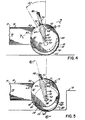
- FIG. 4 depicts the edger apparatus in a stowed position.
- the latch arm 35 has been moved outwardly from the mower to pull the latch tab 39 from the latch-receiving aperture 40 and from the aperture 42, 43, 44, 45 or 46 in which it resides.
- the handle 38 can be pushed downwardly or pulled upwardly, lifting the slide plate 25 within the receiver channel 26 and as well lifting the disk 20 along with it.
- the disk 20 is in a stowed position with the confines of the shroud 22.
- the latch tab 39 extends through the aperture 40 and slide plate 25 and into the upper positioning aperture 46 of the receiver channel 26.
- the disk axis 30 is located above and rearwardly of the axis 59 of the axle 16 and wheel 14. It will also be appreciated that in this embodiment, the disk axis 30 is dis posed on a radial extending from the axis 59.
- the latch arm 35 has been moved outwardly toward the disk and handle 38 pushed downwardly, carrying the slide plate 25 and the disk 20 downwardly, to position the disk 20 in a cutting position with respect to the ground as shown in the figures. In such a position, the sharpened edge 21 of the disk extends below the ground surface on which the mower wheel 15 supports the mower.
- the disk 21 extends downwardly below the level of the ground line or sidewalk, for example, to trim any grass or turf which extends from the lawn, for example, over the pavement.
- the axis 30 has now been moved downwardly and forwardly of the axis 59 of the axle 16 so that the forwardmost portion of the sharpened edge 21 of the disk 20 is approximately in the same vertical disposition as the forwardmost portion of the tread 15 of the wheel 14.
- edging can be accomplished right up to an object, for example, shown in 79 in Fig. 5.
- the angle at which the sharpened edge 21 meets the turf at the level of the ground line is a very acute angle 80, relative of course to the angular disposition of the axis 30 with respect to the axis 59 and the size of the disk.
- the angle 80 is reduced further. As this angle reduces or becomes more acute, the actual cutting efficiency of the disk with respect to the turf to be edged or trimmed, is rendered more efficient, and thus the inertia and the weight of the mower is more effectively used for edging.
- this edging apparatus can be utilized with either a pushed or a self-propelled mower and in a preferred embodiment, is utilized in connection with a self-propelled mower 10. It will also be appreciated, however, that the disk 20 is not driven but is free to rotate and that the weight and inertia of the rotary mower 10, whether of the walk behind, push variety, or the self-propelled variety, is sufficient to effectively cause the disk 20 to cut and edge turf extending over -the sidewalk or other area along which the mower is pushed.
- the mower 10 includes a grass chute 82, only a portion of which is seen in Fig. 1.
- This chute comprises a protrusion out beyond the sidewall 12 and as shown, constitutes a leading portion of the grass chute or a simple enlargement of the mower deck 11 through which the rotary mower blade passes.
- the rotary mower 10 produces a vacuum zone, defined in part by the deck 11 and the various walls of the deck and rotating blade, so as to suck up grass clippings cut by the mower.
- the disk 20 being located on the end of the axle 16 is either within or just proceeds the vacuum zone defined by the mower so that as the disk 20 cuts or edges turf and grass and the mower is rolled over the cut area, the vacuum zone will tend to lift or pick up the cuttings and blow them outwardly through the chute 82 or into the grass catcher associated with the mower.
- the front wheel 14 is relatively closely associated with the enlargement of the deck 11 or the grass chute 82.
- an edging disk is mounted on the end of the front wheel axle, there is a relatively limited area for the disk and disk size, thus, must be limited. If the disk were rotated about the axle 16 in a circular direction as described in the prior patent noted above, the disk size would even be further limited, since it would be limited to a size which must clear the protrusion 82. In this present invention, however, it will be appreciated that the disk is moved in a linear direction, upwardly and downwardly, and is not swung rearwardly toward the protrusion 82 as in the prior patent. Accordingly, the disk 20 may be of a larger size than the disk shown in the prior patent, when the same mower configuration is contemplated. The use of aCDCdisk20 as noted above, facilitates the efficiency of the edging and cutting operation.
- the axis 30 of the disk 20 is moved in a linear direction as the disk is moved between its stowed position as shown in Fig. 4 and its extended position as shown in Fig. 5.
- the axis 30 is not moved in a circular or arcuate direction but rather in a linear fashion, which, in this embodiment, is preferably on a radial, which extends through the axis 59 of the axle 16.
- the axis 30 may be located along a line which is not radial to the axis 59 but may be somewhat offset therefrom.
- an improved edging apparatus which can be utilized on original mowing equipment or can be provided as an after-market add-on.
- the axle 16 of the mower with which the edging apparatus is to be used can comprise a shoulder bolt having an integral head as particularly shown in the drawings hereto.
- an elongated, hexagonal nut for example, can be provided of the proper length for accommodating mounting of the edging apparatus to the mower, or a complete new axle, including a shoulder bolt such as that shown above, can be utilized for those existing mowers which do not use a stub shaft axle but which use an elongated shoulder bolt.
- Fig. 8 depicts such a stub shaft axle 83 mounting a wheel 14 secured to a wall 12a of mower 10a.
- the stub shaft has threaded end 84 into which is secured hexagonal head or nut 85.
- Nut 85 has a threaded through-bore 86 for receiving the bolt 52 to secure the edging apparatus thereon in non-rotational fashion through socket 58.
- the edging disk 20 with its associated mounting apparatus is mounted to the axle 16 and the shroud is thereafter secured over the disk.
- the edging apparatus While closely fitted to the wheel 14, the edging apparatus nevertheless extends somewhat outwardly therefrom. In particularly tight mowing situations, it may be sometimes desirable to remove the apparatus from the mower so that close-in mowing can be obtained. This is easily accomplished by first simply unscrewing the knob 71 (Fig. 1), removing the shroud upwardly over the handle 38 and thereafter moving the latch arm 35 in an outward direction to disengage the latch tab 39 and then pulling on the handle 38 to lift the disk and slide plate 25 from the receiver channel 26 and remove the edging apparatus from the mover. Reassembly is easily accommodated by reverse manipulation.
- edger disk between its various positions defined by the apertures 42-46, or complete removal or assembly, can be a one-handed operation, it only being necessary to grasp the handle 38 to make these adjustments. Since this handle extends above the deck 11, it is not necessary for a user to place his hand close to the disk edge or to the underside of the mower.
Landscapes
- Life Sciences & Earth Sciences (AREA)
- Environmental Sciences (AREA)
- Harvester Elements (AREA)
Applications Claiming Priority (2)
| Application Number | Priority Date | Filing Date | Title |
|---|---|---|---|
| US595210 | 1990-10-10 | ||
| US07/595,210 US5065567A (en) | 1990-10-10 | 1990-10-10 | Lawn edger |
Publications (2)
| Publication Number | Publication Date |
|---|---|
| EP0515751A2 true EP0515751A2 (de) | 1992-12-02 |
| EP0515751A3 EP0515751A3 (en) | 1993-03-17 |
Family
ID=24382235
Family Applications (1)
| Application Number | Title | Priority Date | Filing Date |
|---|---|---|---|
| EP19910309356 Ceased EP0515751A3 (en) | 1990-10-10 | 1991-10-10 | Improved lawn edger |
Country Status (6)
| Country | Link |
|---|---|
| US (1) | US5065567A (de) |
| EP (1) | EP0515751A3 (de) |
| JP (1) | JPH04229105A (de) |
| AU (1) | AU646781B2 (de) |
| CA (1) | CA2053032A1 (de) |
| MX (1) | MX9101250A (de) |
Families Citing this family (25)
| Publication number | Priority date | Publication date | Assignee | Title |
|---|---|---|---|---|
| US5139091A (en) * | 1989-05-15 | 1992-08-18 | Kawasaki Jukogyo Kabushiki Kaisha | Edger with improved operating lever assembly |
| AU648210B2 (en) * | 1992-01-09 | 1994-04-14 | Willmark Pty Limited | Combination blade for lawn edger |
| US6263975B1 (en) * | 1998-07-24 | 2001-07-24 | Black & Decker Inc. | Lawn edger including multi-positionable edge-guide |
| US6092608A (en) * | 1998-11-04 | 2000-07-25 | Leger; Herbert J. | Garden tiller pulverizing/edger attachment |
| AUPR392801A0 (en) * | 2001-03-23 | 2001-04-26 | Parkinson, Ray | Improvements in mowing/cutting equipment |
| US6612376B2 (en) * | 2001-10-16 | 2003-09-02 | Black & Decker Inc. | Hinged edger housing improved internal debris guard and labyrinth perimeter seal |
| US6702350B1 (en) | 2002-09-18 | 2004-03-09 | Ridg-U-Rak, Inc. | Bolted axle wheel assembly |
| US6899345B1 (en) * | 2003-03-26 | 2005-05-31 | John D. Bearden | Lawn mower adjustable wheel conversion assembly |
| US20060011357A1 (en) * | 2004-07-16 | 2006-01-19 | Electrolux Professional Outdoor Products, Inc. | Edging and trenching system |
| US20070012017A1 (en) * | 2005-07-13 | 2007-01-18 | Jacob Blotsky | Machine for edging lawn grass |
| USD576643S1 (en) | 2005-07-13 | 2008-09-09 | Jacob Blotsky | Machine for edging lawn grass |
| US7128164B1 (en) * | 2005-08-03 | 2006-10-31 | Boland Thomas C | Vehicle mounted edging wheel system |
| US20070163221A1 (en) * | 2006-01-19 | 2007-07-19 | Douglas Foster | Edging attachment for riding lawn mowers |
| ITBZ20080006A1 (it) * | 2008-02-19 | 2009-08-20 | Herbert Ladurner | Testa decespugliatrice |
| US7603838B1 (en) * | 2008-03-03 | 2009-10-20 | Henley Jr Horace | Edging attachment for a rotary lawn mower |
| US20090255695A1 (en) * | 2008-04-09 | 2009-10-15 | Original Power, Inc. | Power tool |
| USD608797S1 (en) * | 2009-03-06 | 2010-01-26 | Echo, Inc. | Guard for a beveled edger |
| US9144196B2 (en) | 2009-10-14 | 2015-09-29 | Thomas J. FRANCIS | Lawn care maintenance apparatus |
| US20110083414A1 (en) * | 2009-10-14 | 2011-04-14 | Francis Thomas J | Lawn-care maintenance apparatus |
| US8176989B1 (en) | 2010-02-09 | 2012-05-15 | Valeriy Ponomarenko | Wheeled support for using a trimmer as a hand-held lawn edger |
| US20130118139A1 (en) * | 2011-11-15 | 2013-05-16 | Agri-Fab, Inc. | Sweeper height adjustment assembly |
| US8516783B1 (en) * | 2012-01-24 | 2013-08-27 | Ralph Maldonado | Edging and trimming apparatus for attachment to lawn mowers |
| CA2920175A1 (en) * | 2013-02-08 | 2013-05-01 | Thomas J. Francis | Lawn care maintenance apparatus |
| DE102020123501B3 (de) | 2020-09-09 | 2022-03-10 | Horl 1993 Gmbh | Rollschleifer mit Presspassung zwischen Laufrolle und Achse |
| DE102020133853B3 (de) | 2020-12-16 | 2022-04-28 | Horl 1993 Gmbh | Schneidwerkzeug mit Auflageabschnitt für voreingestellten Schleifwinkel |
Family Cites Families (71)
| Publication number | Priority date | Publication date | Assignee | Title |
|---|---|---|---|---|
| US3123964A (en) * | 1964-03-10 | Lawn edgers | ||
| US117485A (en) * | 1871-07-25 | Improvement in garden-tools for triivir | ||
| US3125165A (en) * | 1964-03-17 | Rotary lawn mower edging attachment | ||
| US1010260A (en) * | 1911-01-12 | 1911-11-28 | William E Hill | Lawn-trimming attachment. |
| US1065946A (en) * | 1912-07-25 | 1913-07-01 | Emil Janson | Lawn-mower attachment. |
| US1181281A (en) * | 1915-10-26 | 1916-05-02 | John Albert | Grass-cutter. |
| US1561823A (en) * | 1924-06-23 | 1925-11-17 | Bishop Frank | Lawn-edging attachment |
| US1732308A (en) * | 1925-08-29 | 1929-10-22 | Livingston Ivan | Lawn-mower attachment |
| US1654574A (en) * | 1927-02-23 | 1928-01-03 | William W Brown | Edge trimmer for lawns |
| DE491135C (de) * | 1927-10-22 | 1930-02-06 | Alfred Emil Kock | Rasenmaeher mit Einrichtung zum Kantenmaehen |
| US1720169A (en) * | 1928-01-10 | 1929-07-09 | Cripe Joe | Lawn trimmer |
| US1763339A (en) * | 1928-11-10 | 1930-06-10 | Andrew E Beck | Edge-trimming attachment for lawn mowers |
| US1770434A (en) * | 1929-06-17 | 1930-07-15 | Schleicher Martin | Lawn-trimming attachment |
| US2270649A (en) * | 1939-05-25 | 1942-01-20 | Hickman M Corley | Lawn trimmer |
| US2506366A (en) * | 1945-02-12 | 1950-05-02 | Estol P Korn | Lawn edger |
| US2483935A (en) * | 1947-03-10 | 1949-10-04 | Henry W Ridenour | Edge trimming attachment for lawn mowers |
| US2525944A (en) * | 1949-02-28 | 1950-10-17 | Gerald P Ralston | Lawn edger |
| US2682825A (en) * | 1950-05-23 | 1954-07-06 | Warholoski August | Lawn mower attachment |
| US2608043A (en) * | 1950-11-09 | 1952-08-26 | George D Berdan | Combined mower and trimmer |
| US2725813A (en) * | 1951-05-12 | 1955-12-06 | Joseph H Stoeber | Combination lawn edger and ditcher |
| US2663137A (en) * | 1951-08-01 | 1953-12-22 | Asbury Corp | Lawn edger |
| US2707858A (en) * | 1953-02-16 | 1955-05-10 | Luther R Norton | Combined lawn mower and edger |
| US2791875A (en) * | 1953-03-03 | 1957-05-14 | Louis D Faas | Lawn mowing and trimming machine |
| US2718838A (en) * | 1954-03-01 | 1955-09-27 | William H Schumacher | Lawn edger and trimmer |
| US2917890A (en) * | 1955-06-23 | 1959-12-22 | Albert G Thomas | Power driven lawn mower and trimmer |
| US2901878A (en) * | 1956-05-21 | 1959-09-01 | Gardex Inc | Lawn trimmer |
| US3057411A (en) * | 1957-01-15 | 1962-10-09 | John P Carlton | Edger attachment |
| US2906080A (en) * | 1957-02-12 | 1959-09-29 | Sr James A Light | Lawn edging attachment for tractors |
| US3019844A (en) * | 1958-11-24 | 1962-02-06 | Milford M Key | Vehicle mounted edgers |
| US3003301A (en) * | 1959-07-21 | 1961-10-10 | Verne R Koon | Power mower edger attachment |
| US3053035A (en) * | 1960-04-14 | 1962-09-11 | David K Earley | Edging attachment for rotary type lawn mower |
| US3150720A (en) * | 1961-01-30 | 1964-09-29 | Wintercorn Andrew F | Attachment for rotary power mowers |
| US3097703A (en) * | 1961-10-04 | 1963-07-16 | Alvik Harold | Digging machine |
| US3130793A (en) * | 1962-06-07 | 1964-04-28 | Albert J Allegretti | Lawn trimmer and edger |
| GB966428A (en) * | 1962-07-09 | 1964-08-12 | Victor Taylor Legge | Improvements in or relating to lawn mowers |
| US3210089A (en) * | 1962-07-16 | 1965-10-05 | Pull R Hoist Company | Variable wheel suspension |
| US3192693A (en) * | 1963-07-02 | 1965-07-06 | Bergeson Ragnvald | Trimmer attachment for power lawn mower |
| US3322201A (en) * | 1964-09-28 | 1967-05-30 | Thomas F Ballister | Lawn edge trimmer attachment |
| US3346053A (en) * | 1965-02-12 | 1967-10-10 | Albert J Allegretti | Lawn edger |
| US3357497A (en) * | 1965-05-04 | 1967-12-12 | Joseph J Simolka | Sidewalk edger |
| US3430424A (en) * | 1965-08-06 | 1969-03-04 | Toro Mfg Corp | Edge trimmer |
| US3404520A (en) * | 1965-10-21 | 1968-10-08 | Internat Patent Res Corp | Lawn edger |
| US3421300A (en) * | 1965-12-21 | 1969-01-14 | Charles W Rhodes | Edger attachment for power driven lawn mowers |
| US3489225A (en) * | 1967-04-21 | 1970-01-13 | James S Bass | Lawn mower mounted trimming attachment |
| US3475887A (en) * | 1967-12-26 | 1969-11-04 | Leon V Price | Lawn edger having cuttings collection means |
| US3531922A (en) * | 1968-06-20 | 1970-10-06 | Louis H Hansen | Trimmer and edger attachment for a power mower |
| US3668845A (en) * | 1970-03-09 | 1972-06-13 | Parkton Corp | Lawn mower apparatus |
| US3710563A (en) * | 1970-11-09 | 1973-01-16 | M Polette | Rotary edger for use with power driven lawn mower |
| US3698165A (en) * | 1971-03-03 | 1972-10-17 | Ernest W Keesee | Edger for lawn mower |
| US3734196A (en) * | 1971-09-03 | 1973-05-22 | E Mangum | Lawn edger |
| US3690384A (en) * | 1971-11-03 | 1972-09-12 | Luther E Patterson | Combined lawn mower and edger |
| US3803818A (en) * | 1973-01-23 | 1974-04-16 | C Chaney | Rotary mower with selectively actuatable edger |
| US3907039A (en) * | 1973-10-05 | 1975-09-23 | Charles G Remley | Turf edging apparatus for tractors and the like |
| US3907040A (en) * | 1974-01-23 | 1975-09-23 | Von Aldo Trusty | Power operated lawn edger |
| AU518556B2 (en) * | 1977-05-18 | 1981-10-08 | William Quintel Francis | Grass cutting machine |
| US4170099A (en) * | 1978-04-06 | 1979-10-09 | Owens Boyd L | Power mower edger and trimmer attachment |
| US4200155A (en) * | 1978-08-31 | 1980-04-29 | Excel Industries, Inc. | Lawn edger attachment |
| US4318267A (en) * | 1980-10-01 | 1982-03-09 | Green Robert W | Grass edging device |
| US4321785A (en) * | 1980-12-08 | 1982-03-30 | Ataco Steel Products Co. | Wheel height adjuster |
| AU7830781A (en) * | 1981-10-14 | 1983-04-21 | Charles Maxwell Morris | Edger for lawn mower |
| US4463544A (en) * | 1982-05-03 | 1984-08-07 | Allegretti & Company | Edger |
| US4453372A (en) * | 1983-02-28 | 1984-06-12 | Remer Fred J | Grass edger and trimmer attachment |
| US4478028A (en) * | 1984-02-02 | 1984-10-23 | Dawson Jr Gerthen L | Demountable lawn edger/mower combination |
| US4589252A (en) * | 1984-09-17 | 1986-05-20 | Williams Will T | Steep terrain stabilizing devices for lawn mowers |
| US4551967A (en) * | 1985-03-04 | 1985-11-12 | Murcko Joseph S | Combination lawnmower and edger |
| US4642976A (en) * | 1985-09-20 | 1987-02-17 | Owens Boyd L | Lawn mower trimmer and edger attachment |
| US4718221A (en) * | 1986-05-21 | 1988-01-12 | Wessel Lloyd E | Lawnmower edger and trimmer |
| US4852658A (en) * | 1987-06-22 | 1989-08-01 | Wessel Lloyd E | Mounted edger |
| US4896488A (en) * | 1988-12-29 | 1990-01-30 | Duncan Larry A | Trimming attachment for a lawn mower etc. |
| US4949536A (en) * | 1989-07-06 | 1990-08-21 | George Neufeld | Lawn and garden trimmer apparatus |
| US4965990A (en) * | 1989-09-11 | 1990-10-30 | Slawson Sr Earnest E | Lawn mower and edger assembly |
-
1990
- 1990-10-10 US US07/595,210 patent/US5065567A/en not_active Expired - Fee Related
-
1991
- 1991-09-18 AU AU84557/91A patent/AU646781B2/en not_active Ceased
- 1991-09-25 MX MX9101250A patent/MX9101250A/es unknown
- 1991-10-08 CA CA002053032A patent/CA2053032A1/en not_active Abandoned
- 1991-10-08 JP JP3260611A patent/JPH04229105A/ja active Pending
- 1991-10-10 EP EP19910309356 patent/EP0515751A3/en not_active Ceased
Also Published As
| Publication number | Publication date |
|---|---|
| EP0515751A3 (en) | 1993-03-17 |
| AU646781B2 (en) | 1994-03-03 |
| CA2053032A1 (en) | 1992-04-11 |
| JPH04229105A (ja) | 1992-08-18 |
| US5065567A (en) | 1991-11-19 |
| AU8455791A (en) | 1992-04-16 |
| MX9101250A (es) | 1992-06-05 |
Similar Documents
| Publication | Publication Date | Title |
|---|---|---|
| US5065567A (en) | Lawn edger | |
| US4718221A (en) | Lawnmower edger and trimmer | |
| US5662172A (en) | Aerator appartus with retractable turf penetrating members | |
| US5101617A (en) | Lawn mower flap mount | |
| US5423126A (en) | Flexible flail trimmer | |
| US6796113B2 (en) | Guard and dolly for line trimming apparatus | |
| US4478028A (en) | Demountable lawn edger/mower combination | |
| US8544246B2 (en) | Self engaging wing lawn mower | |
| US6966168B1 (en) | Trimmer caddie for mower deck | |
| US5077898A (en) | Trimmer shield and mounting | |
| US6397572B1 (en) | Lawnmower mountable trimming device | |
| US4796415A (en) | Dolly for line trimming apparatus | |
| US7650739B2 (en) | Mulch plate apparatus with adjustable handle mechanism | |
| US6601374B2 (en) | Weed trimmer to mower attachment kit | |
| US7337602B1 (en) | Mulch plate apparatus with adjustable handle mechanism | |
| US4852658A (en) | Mounted edger | |
| US10045481B2 (en) | Lawnmower discharge device | |
| US4458472A (en) | Lawn mower zone start system | |
| CA2767680C (en) | Lawn-care maintenance apparatus | |
| US20030093983A1 (en) | Maneuverable and adjustable lawn mower having an edger-trimming unit | |
| GB2240023A (en) | Deflector for cuttings outlet of mowers | |
| US5018239A (en) | Mower attachment | |
| EP3703484B1 (de) | Rasenmäher mit fallgriff | |
| US7526909B1 (en) | Quickly installable mulch-type accessory for a walk-behind or riding mower | |
| EP3417692B1 (de) | Entladeschutzanordnung für einen mäher |
Legal Events
| Date | Code | Title | Description |
|---|---|---|---|
| PUAI | Public reference made under article 153(3) epc to a published international application that has entered the european phase |
Free format text: ORIGINAL CODE: 0009012 |
|
| AK | Designated contracting states |
Kind code of ref document: A2 Designated state(s): AT BE CH DE DK ES FR GB GR IT LI LU NL SE |
|
| PUAL | Search report despatched |
Free format text: ORIGINAL CODE: 0009013 |
|
| AK | Designated contracting states |
Kind code of ref document: A3 Designated state(s): AT BE CH DE DK ES FR GB GR IT LI LU NL SE |
|
| 17P | Request for examination filed |
Effective date: 19930827 |
|
| 17Q | First examination report despatched |
Effective date: 19941223 |
|
| STAA | Information on the status of an ep patent application or granted ep patent |
Free format text: STATUS: THE APPLICATION HAS BEEN REFUSED |
|
| 18R | Application refused |
Effective date: 19951218 |