EP0515570B1 - Vorrichtung zur aeroben reinigung von abwasser - Google Patents
Vorrichtung zur aeroben reinigung von abwasser Download PDFInfo
- Publication number
- EP0515570B1 EP0515570B1 EP19910905995 EP91905995A EP0515570B1 EP 0515570 B1 EP0515570 B1 EP 0515570B1 EP 19910905995 EP19910905995 EP 19910905995 EP 91905995 A EP91905995 A EP 91905995A EP 0515570 B1 EP0515570 B1 EP 0515570B1
- Authority
- EP
- European Patent Office
- Prior art keywords
- vessels
- vessel
- settling tank
- cleaning
- passage
- Prior art date
- Legal status (The legal status is an assumption and is not a legal conclusion. Google has not performed a legal analysis and makes no representation as to the accuracy of the status listed.)
- Expired - Lifetime
Links
- 239000002351 wastewater Substances 0.000 title claims abstract description 11
- 238000000746 purification Methods 0.000 title 1
- 238000004140 cleaning Methods 0.000 claims abstract description 25
- 238000005192 partition Methods 0.000 claims description 21
- 239000000463 material Substances 0.000 claims description 4
- 230000007423 decrease Effects 0.000 claims 1
- XLYOFNOQVPJJNP-UHFFFAOYSA-N water Substances O XLYOFNOQVPJJNP-UHFFFAOYSA-N 0.000 abstract description 13
- 229910052760 oxygen Inorganic materials 0.000 abstract description 3
- 239000001301 oxygen Substances 0.000 abstract description 3
- QVGXLLKOCUKJST-UHFFFAOYSA-N atomic oxygen Chemical compound [O] QVGXLLKOCUKJST-UHFFFAOYSA-N 0.000 abstract description 2
- 239000012080 ambient air Substances 0.000 abstract 1
- 239000010802 sludge Substances 0.000 description 8
- 239000007788 liquid Substances 0.000 description 6
- 238000000034 method Methods 0.000 description 3
- 241000894006 Bacteria Species 0.000 description 2
- VSCWAEJMTAWNJL-UHFFFAOYSA-K aluminium trichloride Chemical compound Cl[Al](Cl)Cl VSCWAEJMTAWNJL-UHFFFAOYSA-K 0.000 description 2
- 239000007921 spray Substances 0.000 description 2
- ILRRQNADMUWWFW-UHFFFAOYSA-K aluminium phosphate Chemical compound O1[Al]2OP1(=O)O2 ILRRQNADMUWWFW-UHFFFAOYSA-K 0.000 description 1
- 229940001007 aluminium phosphate Drugs 0.000 description 1
- 229910000147 aluminium phosphate Inorganic materials 0.000 description 1
- 238000011109 contamination Methods 0.000 description 1
- 238000007599 discharging Methods 0.000 description 1
- 238000010438 heat treatment Methods 0.000 description 1
- 238000009434 installation Methods 0.000 description 1
- FBAFATDZDUQKNH-UHFFFAOYSA-M iron chloride Chemical compound [Cl-].[Fe] FBAFATDZDUQKNH-UHFFFAOYSA-M 0.000 description 1
- 229910000398 iron phosphate Inorganic materials 0.000 description 1
- WBJZTOZJJYAKHQ-UHFFFAOYSA-K iron(3+) phosphate Chemical compound [Fe+3].[O-]P([O-])([O-])=O WBJZTOZJJYAKHQ-UHFFFAOYSA-K 0.000 description 1
- 229910052751 metal Inorganic materials 0.000 description 1
- 239000002184 metal Substances 0.000 description 1
- 230000002906 microbiologic effect Effects 0.000 description 1
- 244000005700 microbiome Species 0.000 description 1
- 150000002926 oxygen Chemical class 0.000 description 1
- 238000001556 precipitation Methods 0.000 description 1
- 230000000630 rising effect Effects 0.000 description 1
- 239000013049 sediment Substances 0.000 description 1
- 125000006850 spacer group Chemical group 0.000 description 1
Images

Classifications
-
- C—CHEMISTRY; METALLURGY
- C02—TREATMENT OF WATER, WASTE WATER, SEWAGE, OR SLUDGE
- C02F—TREATMENT OF WATER, WASTE WATER, SEWAGE, OR SLUDGE
- C02F3/00—Biological treatment of water, waste water, or sewage
- C02F3/28—Anaerobic digestion processes
- C02F3/2806—Anaerobic processes using solid supports for microorganisms
-
- B—PERFORMING OPERATIONS; TRANSPORTING
- B01—PHYSICAL OR CHEMICAL PROCESSES OR APPARATUS IN GENERAL
- B01D—SEPARATION
- B01D21/00—Separation of suspended solid particles from liquids by sedimentation
- B01D21/0039—Settling tanks provided with contact surfaces, e.g. baffles, particles
- B01D21/0042—Baffles or guide plates
-
- B—PERFORMING OPERATIONS; TRANSPORTING
- B01—PHYSICAL OR CHEMICAL PROCESSES OR APPARATUS IN GENERAL
- B01D—SEPARATION
- B01D21/00—Separation of suspended solid particles from liquids by sedimentation
- B01D21/0039—Settling tanks provided with contact surfaces, e.g. baffles, particles
- B01D21/0066—Settling tanks provided with contact surfaces, e.g. baffles, particles with a meandering flow pattern of liquid or solid particles
-
- B—PERFORMING OPERATIONS; TRANSPORTING
- B01—PHYSICAL OR CHEMICAL PROCESSES OR APPARATUS IN GENERAL
- B01D—SEPARATION
- B01D21/00—Separation of suspended solid particles from liquids by sedimentation
- B01D21/0087—Settling tanks provided with means for ensuring a special flow pattern, e.g. even inflow or outflow
-
- B—PERFORMING OPERATIONS; TRANSPORTING
- B01—PHYSICAL OR CHEMICAL PROCESSES OR APPARATUS IN GENERAL
- B01D—SEPARATION
- B01D21/00—Separation of suspended solid particles from liquids by sedimentation
- B01D21/02—Settling tanks with single outlets for the separated liquid
-
- B—PERFORMING OPERATIONS; TRANSPORTING
- B01—PHYSICAL OR CHEMICAL PROCESSES OR APPARATUS IN GENERAL
- B01D—SEPARATION
- B01D21/00—Separation of suspended solid particles from liquids by sedimentation
- B01D21/24—Feed or discharge mechanisms for settling tanks
- B01D21/2427—The feed or discharge opening located at a distant position from the side walls
-
- B—PERFORMING OPERATIONS; TRANSPORTING
- B01—PHYSICAL OR CHEMICAL PROCESSES OR APPARATUS IN GENERAL
- B01D—SEPARATION
- B01D21/00—Separation of suspended solid particles from liquids by sedimentation
- B01D21/24—Feed or discharge mechanisms for settling tanks
- B01D21/2488—Feed or discharge mechanisms for settling tanks bringing about a partial recirculation of the liquid, e.g. for introducing chemical aids
-
- B—PERFORMING OPERATIONS; TRANSPORTING
- B01—PHYSICAL OR CHEMICAL PROCESSES OR APPARATUS IN GENERAL
- B01F—MIXING, e.g. DISSOLVING, EMULSIFYING OR DISPERSING
- B01F23/00—Mixing according to the phases to be mixed, e.g. dispersing or emulsifying
- B01F23/20—Mixing gases with liquids
- B01F23/23—Mixing gases with liquids by introducing gases into liquid media, e.g. for producing aerated liquids
- B01F23/234—Surface aerating
- B01F23/2341—Surface aerating by cascading, spraying or projecting a liquid into a gaseous atmosphere
- B01F23/23411—Surface aerating by cascading, spraying or projecting a liquid into a gaseous atmosphere by cascading the liquid
-
- C—CHEMISTRY; METALLURGY
- C02—TREATMENT OF WATER, WASTE WATER, SEWAGE, OR SLUDGE
- C02F—TREATMENT OF WATER, WASTE WATER, SEWAGE, OR SLUDGE
- C02F3/00—Biological treatment of water, waste water, or sewage
- C02F3/02—Aerobic processes
- C02F3/06—Aerobic processes using submerged filters
-
- C—CHEMISTRY; METALLURGY
- C02—TREATMENT OF WATER, WASTE WATER, SEWAGE, OR SLUDGE
- C02F—TREATMENT OF WATER, WASTE WATER, SEWAGE, OR SLUDGE
- C02F3/00—Biological treatment of water, waste water, or sewage
- C02F3/02—Aerobic processes
- C02F3/12—Activated sludge processes
- C02F3/24—Activated sludge processes using free-fall aeration or spraying
-
- Y—GENERAL TAGGING OF NEW TECHNOLOGICAL DEVELOPMENTS; GENERAL TAGGING OF CROSS-SECTIONAL TECHNOLOGIES SPANNING OVER SEVERAL SECTIONS OF THE IPC; TECHNICAL SUBJECTS COVERED BY FORMER USPC CROSS-REFERENCE ART COLLECTIONS [XRACs] AND DIGESTS
- Y02—TECHNOLOGIES OR APPLICATIONS FOR MITIGATION OR ADAPTATION AGAINST CLIMATE CHANGE
- Y02W—CLIMATE CHANGE MITIGATION TECHNOLOGIES RELATED TO WASTEWATER TREATMENT OR WASTE MANAGEMENT
- Y02W10/00—Technologies for wastewater treatment
- Y02W10/10—Biological treatment of water, waste water, or sewage
Definitions
- the present invention relates to a device for aerobic cleaning of waste water comprising at least one vessel equipped for aerobic cleaning.
- the vessel suitable for aerobic cleaning is formed by a channel extending around the centre wherein the water for cleaning is subjected to a movement flowing around the centre.
- the object of the present invention is therefore to provide such a device for aerobic cleaning wherein the contact between waste water for cleaning and air is much more intensive.
- This object is achieved by a series of vessels connected in cascade and opened at their top.
- the device comprises such a series of vessels connected in cascade, wherein the liquid for cleaning flows from the one vessel to the other, the contact between waste water for cleaning and air is intensified; the contact area between air and water is herein formed not only by the liquid surface in the vessels but also by the surface of the liquid flow from the one vessel to the following vessel.
- Devices for aerobic cleaning are otherwise known wherein the waste water for cleaning is sprayed above a vessel.
- the dimensions of such installations are in general exceptionally large so that they are not suitable for comparatively small-scale devices as in the present invention.
- a spray device is arranged in a position preceding the first vessel.
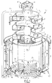
- the device according to the present invention is formed by a base plate 1 which rests on a ground by means of feet 2.
- the device can be set precisely horizontal by means of the feet 2. This is of great importance for the operation of the device since, if its position is not precisely horizontal, liquid flows to one side and only a small part of the device is effective.
- a pillar 3 is fixed in the middle of the round base plate 1 by means of a flange 4.
- the mentioned components are manufactured from metal. It is also possible to use plastic.
- a settling tank 6 Arranged around the top portion of pillar 3 is the device for aerobic cleaning, while around the bottom portion of the pillar is arranged a settling tank 6.
- the device 5 for aerobic cleaning is formed by a series of vessels 7, 8 connected in cascade and arranged concentrically relative to the pillar 3.
- Welded to the pillar 3 are three angle supports 9.
- a threaded rod is fastened in a hole arranged in each of the angle supports.
- the relevant vessel 7 rests on the upper part of the threaded rods so that the vessel 7 can be set precisely horizontally.
- each vessel 7 On its outside the vessel 7 is provided with an overflow edge 11.
- an annular vessel 8 Arranged under each vessel 7 is an annular vessel 8 which is connected by means of spacers 12 to the round vessel 7 arranged thereabove.
- Each of the annular vessels 8 is provided with an overflow edge 13 on its inside.
- a discharge pipe x Arranged in the side wall at the bottom of both upper vessels 7 and 8 is a discharge pipe x which debouches into a common discharge pipe, in which a stop valve is arranged so that contamination or blockage occurring in the top vessels can be sprayed loose using a hose and can be discharged via the discharge pipes.
- a conical cover 14 Arranged at the top of pillar 3 is a conical cover 14 provided at its top with an opening through which extends a feed pipe 15.
- the feed pipe 15 is connected to a pump 16.
- a cap 17 Arranged above the conical cover 14 is a cap 17 provided with a conical part 18 and a cylindrical part 19. The conical cap 17 rests on the conical cover 14 by means of slopingly extending supports 20.
- the settling tank 6 is formed by an exterior tank wall 21 which joins via a weld seam 22 onto a base plate 23 with the form of an annular cone segment.
- the base plate 23 is joined with a weld seam to the actual base plate 1.
- a cylindrical partition wall 25 extends upwards from the base plate 1.
- the partition wall 25 is provided with a zigzag edge 26.
- an interior partition wall 27 Arranged between the pillar 3 and the cylindrical partition wall 25 is an interior partition wall 27 which is provided on its bottom part with openings 28. At its top this interior partition wall is joined to the pillar 3 using supports 29.
- An external partition wall 30 further extends between the cylindrical partition wall 25 and the outer wall 21. This rests at its bottom on triangular supports 31 welded onto the sloping base plate 23. This results in a passage through beneath the external partition wall 30.
- the above described settling tank 6 comprises four communicating chambers, namely a first chamber 32 situated between the pillar 3 and the internal partition wall 27; a second chamber 33 situated between the internal partition wall 27 and the cylindrical partition wall 25; a third chamber 34 situated between the cylindrical partition wall 25 and the external partition wall 30 and, finally, the fourth chamber 35 situated between the external partition wall 30 and the external tank wall 21.
- the third chamber and the fourth chamber can also be considered a single space, wherein the external partition wall functions as baffle.
- plastic rings 50 which enlarges the surface area onto which microbiological organisms can adhere. It is also possible to employ other filling material having the desired ratio between surface area and volume, for instance in the order of 200 m2/m3, like the vessels 7 and 8.
- an overflow channel 36 On the outside of the exterior tank wall 21 is arranged an overflow channel 36, while the upper part of the exterior tank wall 21 is provided with a zigzag wall 37. It is likewise possible to use a curled overflow edge as in the case of the vessels 7 and 8. Connected to the overflow channel 36 is a discharge pipe 38.
- Two discharge pipes 39 are connected to the underside of the base plate.
- a discharge pipe 40 is further connected to the fourth chamber 35. This discharge pipe 40 extends to a relatively short distance from the base plate 23.
- a discharge pipe 51 Arranged in the outer wall 21 is a discharge pipe 51 which extends into chamber 35 to a short distance below liquid level. This discharge pipe also leads from the septic tank.
- Waste water for cleaning coming from a buffer means such as a septic tank is supplied via feed pipe 15 by means of a pump 16. This water sprays out of the opening in the pipe 15 and then strikes against the cap 17 where it is divided into drops and falls downward so that it drips into the uppermost round vessel 7. Aerobic cleaning takes place during this dripping.
- cap 17 is fixed, it can be useful for calculation of the optimum control to give the cap 17 an adjustable form, for instance by means of bent threaded rods replacing the supports 20.
- the micro-organisms present on the plastic rings 50 in the first chamber 32 form a sludge which collects at the bottom of the first chamber 32.
- the remaining water by now for the most part cleaned, passes through the openings 28 in wall 27 and enters the second chamber 27. There it will rise to the level of the overflow edge 26 and flow thereover so that it enters the third chamber. Via the space under the partition 30 the water finally enters the fourth chamber 35.
- the still remaining heavy material will here also collect at the bottom of the third and fourth chambers.
- the water, now to a large degree clean passes over the overflow edge 37 and falls into the overflow channel 36.
- the cleaned water is carried away therefrom via a discharge pipe 38.
- a part of the water situated in the second and in the bottom of the third chamber is drawn via the openings 43 into the annular pipes 41 and 42 respectively and fed via the respective discharge pipes 44 and 45 to the feed channel 15 so that this water is subjected once again to the same treatment. It is possible to interrupt this process by actuating the respective stop valves 46 and 47.
- the material located at the bottom of the first chamber 32 is carried away via discharge pipes 39.
- the sludge level detector 49 is arranged which, when the sludge reaches the relevant level, starts the process of discharging the sludge via the discharge pipe 40 of the septic tank.
- the vessels 7, 8 take not a round but a square form.
- the pillar 3 is omitted here.
- the vessels 7, 8 are each connected via supports 52 to four posts 53, only two of which are shown in fig. 2. These supports 52 are welded to the associated vessels 7, 8, although they can also be connected to the vessels 7 and 8 by means of a screw adjustment connection not shown in the drawing. Such a screw adjustment connection permits accurate horizontal setting of the vessels 7, 8.
- the fact that four separate posts are arranged also contributes to the ease with which the vessels 7, 8 can be set precisely horizontal.
- the conical cap 17 is replaced with a rectangular cap 54.
- a set of baffles 55, 56 is further arranged in each of the vessels 7, 8.
- baffles ensure that the circulation in the vessels 7, 8 is improved so that anaerobic situations are avoided.
- the forming of short-circuit circulation flows is also prevented.
- the baffles 55, 56 are otherwise fixed to the bottom of the relevant vessels 7, 8 via legs not shown in the drawing.
- a perforated plate 57 is also arranged in each of the vessels 7. This perforated plate also rests on the bottom of the relevant vessel 7 via legs not shown in the drawing.
- These perforated plates also improve the circulation; they are therefore only arranged in the vessels 7, in which flow takes place from inside to outside, thus deceleratingly. It is noted here that it is in such a situation that there is the greatest danger of a less good circulation occurring; in the vessels 8 the flow direction is from outside to inside, wherein the water flow is accelerated.
- baffles and perforated plates are shown in the present embodiment of rectangular vessels 7, 8, it is also applicable with round vessels 7, 8.
- a round settling tank is discussed in the described embodiment, it is possible to use a settling tank with another form, for instance a rectangular or square settling tank.
- a cascade (not shown in the drawing) can be arranged behind the discharge pipe 38, this cascade being otherwise easy to build on against the outer wall.
- the device according to the invention can be provided with a heating element.
Landscapes
- Chemical & Material Sciences (AREA)
- Chemical Kinetics & Catalysis (AREA)
- Life Sciences & Earth Sciences (AREA)
- Microbiology (AREA)
- Engineering & Computer Science (AREA)
- Hydrology & Water Resources (AREA)
- Biodiversity & Conservation Biology (AREA)
- Environmental & Geological Engineering (AREA)
- Water Supply & Treatment (AREA)
- Organic Chemistry (AREA)
- Biological Treatment Of Waste Water (AREA)
- Aeration Devices For Treatment Of Activated Polluted Sludge (AREA)
- Treatment Of Biological Wastes In General (AREA)
- Purification Treatments By Anaerobic Or Anaerobic And Aerobic Bacteria Or Animals (AREA)
- Physical Water Treatments (AREA)
Claims (14)
- Vorrichtung zur aeroben Reinigung von Abwasser mit mindestens einem für aerobe Reinigung ausgerüsteten Behälter, gekennzeichnet durch eine Serie von in Kaskade geschalteten und oben offenen Behältern, wobei die Behalter jeweils im wesentlichen konzentrisch zueinander sind und eine solche Form haben, daß sich die Überlaufkante eines Behälters gerade über dem unterhalb dieses Behälters angeordneten Behälter befindet.
- Vorrichtung nach Anspruch 1,
dadurch gekennzeichnet, daß die Behälter abwechselnd eine große und eine kleine Größe haben, wobei die Überlaufkante an der Außenseite der kleinen Behälter und an der Innenseite der großen Behälter angeordnet ist. - Vorrichtung nach Anspruch 1,
dadurch gekennzeichnet, daß die Behälter rund oder ringförmig sind. - Vorrichtung nach Anspruch 2 oder 3,
dadurch gekennzeichnet, daß die großen Behälter jeweils an dem direkt darüber befindlichen Behälter befestigt sind und daß die Behälter an einer konzentrisch zu den Behältern angeordneten Säule befestigt sind. - Vorrichtung nach Anspruch 1 oder 2,
dadurch gekennzeichnet, daß die Behälter rechteckig sind. - Vorrichtung nach Anspruch 3 oder 5,
dadurch gekennzeichnet, daß die Behälter jeweils an Stützen befestigt sind, die außerhalb der Behälter verlaufen. - Vorrichtung nach einem der Ansprüche,
dadurch gekennzeichnet, daß in den Behältern Blenden angeordnet sind. - Vorrichtung nach Anspruch 7,
dadurch gekennzeichnet, daß zwei im wesentlichen parallele Blenden in jedem der Behälter angeordnet sind und daß zwischen den Blenden eine perforierte Platte befestigt ist, wobei der Abstand zwischen dem Boden des Behälters, in dem die perforierte Platte befestigt ist, und der Platte in Strömungsrichtung abnimmt. - Vorrichtung nach einem der vorangehenden Ansprüche,
dadurch gekennzeichnet, daß ein Absetztank unter den in Kaskade geschalteten Behältern angeordnet ist. - Vorrichtung nach Anspruch 9,
dadurch gekennzeichnet, daß der Absetztank konzentrisch zu einer Mittelsäule ist und daß der Absetztank durch kreisförmige konzentrische Trennwände unterteilt ist. - Vorrichtung nach Anspruch 10,
dadurch gekennzeichnet, daß die Trennwände abwechselnd in Radialrichtung mit einem an der Unterseite der Trennwände angeordneten Durchlaß versehen sind. - Vorrichtung nach Anspruch 11,
dadurch gekennzeichnet, daß der Durchlaß dadurch gebildet ist, daß sich die Trennwand nicht bis zum Boden des Absetztanks erstreckt, oder dadurch, daß der Durchlaß von in der Trennwand angeordneten Löchern gebildet ist. - Vorrichtung nach Anspruch 10, 11 oder 12,
dadurch gekennzeichnet, daß im Bereich des Durchlasses ein Kanal vorgesehen ist, der sich rundum erstreckt und mit Öffnungen versehen ist. - Vorrichtung nach einem der Ansprüche 8 bis 12,
dadurch gekennzeichnet, daß der Absetztank mit Schüttmaterial gefüllt ist, dessen Verhältnis zwischen Oberfläche und Volumen groß ist.
Applications Claiming Priority (2)
| Application Number | Priority Date | Filing Date | Title |
|---|---|---|---|
| NL9000432A NL9000432A (nl) | 1990-02-22 | 1990-02-22 | Inrichting voor aerobe reiniging van afvalwater. |
| NL9000432 | 1990-02-22 |
Publications (2)
| Publication Number | Publication Date |
|---|---|
| EP0515570A1 EP0515570A1 (de) | 1992-12-02 |
| EP0515570B1 true EP0515570B1 (de) | 1994-01-19 |
Family
ID=19856652
Family Applications (1)
| Application Number | Title | Priority Date | Filing Date |
|---|---|---|---|
| EP19910905995 Expired - Lifetime EP0515570B1 (de) | 1990-02-22 | 1991-02-21 | Vorrichtung zur aeroben reinigung von abwasser |
Country Status (7)
| Country | Link |
|---|---|
| EP (1) | EP0515570B1 (de) |
| AT (1) | ATE100427T1 (de) |
| DE (1) | DE69101057T2 (de) |
| DK (1) | DK0515570T3 (de) |
| ES (1) | ES2048591T3 (de) |
| NL (1) | NL9000432A (de) |
| WO (1) | WO1991013033A1 (de) |
Families Citing this family (8)
| Publication number | Priority date | Publication date | Assignee | Title |
|---|---|---|---|---|
| ES2059229B1 (es) * | 1992-02-17 | 1995-03-16 | Dihidrox S A | Sistema de depuracion de aguas residuales mediante lagunas de estabilizacion. |
| FR2702469A1 (fr) * | 1993-03-12 | 1994-09-16 | Egretier Jean Michel | Dispositif d'épuration des eaux résiduaires. |
| FR2702470B1 (fr) * | 1993-03-12 | 1996-04-12 | Egretier Jean Michel | Dispositif d'epuration des eaux residuaires. |
| DE19728400A1 (de) * | 1997-06-20 | 1998-12-24 | Herzberger Baeckerei Gmbh | Aufbereitungsanlage für Wasser |
| GB9814591D0 (en) * | 1998-07-07 | 1998-09-02 | Wrc Plc | Process for sewage and wastewater treatment |
| JP4936791B2 (ja) * | 2006-05-22 | 2012-05-23 | 株式会社東芝 | 曝気レス水処理装置 |
| ES2385510B1 (es) * | 2009-11-26 | 2013-05-16 | Edarma, S.L. | Reactor para el tratamiento aeróbico de fluidos y un procedimiento para el tratamiento aeróbico de un fluido a tratar. |
| CN113754060A (zh) * | 2021-10-11 | 2021-12-07 | 北京建筑大学 | 一种分散污水多反应区一体化组合处理系统及方法 |
Family Cites Families (4)
| Publication number | Priority date | Publication date | Assignee | Title |
|---|---|---|---|---|
| NL18659C (de) * | ||||
| FR397023A (fr) * | 1908-12-02 | 1909-04-27 | Jean Baudet | Fosse septique |
| US4042510A (en) * | 1976-09-02 | 1977-08-16 | Canton Textile Mills, Inc. | Liquid aeration device |
| CS251715B1 (en) * | 1985-02-22 | 1987-07-16 | Milon Fiala | Apparatus for multigrade biological cleaning organicaly poluted waste waters |
-
1990
- 1990-02-22 NL NL9000432A patent/NL9000432A/nl not_active Application Discontinuation
-
1991
- 1991-02-21 ES ES91905995T patent/ES2048591T3/es not_active Expired - Lifetime
- 1991-02-21 EP EP19910905995 patent/EP0515570B1/de not_active Expired - Lifetime
- 1991-02-21 WO PCT/NL1991/000030 patent/WO1991013033A1/en not_active Ceased
- 1991-02-21 DE DE91905995T patent/DE69101057T2/de not_active Expired - Fee Related
- 1991-02-21 AT AT91905995T patent/ATE100427T1/de not_active IP Right Cessation
- 1991-02-21 DK DK91905995T patent/DK0515570T3/da active
Also Published As
| Publication number | Publication date |
|---|---|
| EP0515570A1 (de) | 1992-12-02 |
| DE69101057D1 (de) | 1994-03-03 |
| WO1991013033A1 (en) | 1991-09-05 |
| ATE100427T1 (de) | 1994-02-15 |
| DK0515570T3 (da) | 1994-05-30 |
| DE69101057T2 (de) | 1994-05-05 |
| NL9000432A (nl) | 1991-09-16 |
| ES2048591T3 (es) | 1994-03-16 |
Similar Documents
| Publication | Publication Date | Title |
|---|---|---|
| CA1257413A (en) | Apparatus for clarification of water | |
| US4202774A (en) | Flow distributor for fluid bed biological reactor | |
| US5620602A (en) | Method and apparatus for aerobic digestion of organic waste | |
| US4650577A (en) | Apparatus for treating and purifying waste water | |
| EP0515570B1 (de) | Vorrichtung zur aeroben reinigung von abwasser | |
| US4655918A (en) | Apparatus for cleaning waste water | |
| US4251371A (en) | Device for the biological purification of waste water | |
| US3807563A (en) | Individual household aerated waste treatment system | |
| EP1809965B1 (de) | Vorrichtung und verfahren zur rückgewinnung von wärme aus abwasser | |
| CA1105845A (en) | Method and apparatus for separating solids from liquids | |
| US6428656B1 (en) | Water-cooled distilling apparatus | |
| CN207046945U (zh) | 一种厌氧反应器的布水装置 | |
| CN101348303B (zh) | 微动力一体化生活污水净化装置 | |
| US20170072373A1 (en) | System for mixing industrial waste water within a gravity settling tank | |
| US20160089619A1 (en) | System for mixing industrial waste water within a gravity settling tank | |
| US3442495A (en) | Apparatus for aerating waste water | |
| EP0521583B1 (de) | Herstellungsverfahren für Trennvorrichtungen | |
| US4726899A (en) | Apparatus for anaerobic digestion of organic waste | |
| IE920784A1 (en) | Effluent treatment systems | |
| JPS6265794A (ja) | 種汚泥の簡易製造装置 | |
| US20090200687A1 (en) | Treatment system for liquid | |
| US20090101556A1 (en) | Reactor and method for decalcifying water and simultaneous removal of pollutants | |
| CN208087295U (zh) | 用于处理污水的分体式快速处理装置 | |
| JPS6335840Y2 (de) | ||
| EP0798026B1 (de) | Reaktionsgefäss |
Legal Events
| Date | Code | Title | Description |
|---|---|---|---|
| PUAI | Public reference made under article 153(3) epc to a published international application that has entered the european phase |
Free format text: ORIGINAL CODE: 0009012 |
|
| 17P | Request for examination filed |
Effective date: 19920728 |
|
| AK | Designated contracting states |
Kind code of ref document: A1 Designated state(s): AT BE CH DE DK ES FR GB GR IT LI LU NL SE |
|
| 17Q | First examination report despatched |
Effective date: 19930407 |
|
| GRAA | (expected) grant |
Free format text: ORIGINAL CODE: 0009210 |
|
| AK | Designated contracting states |
Kind code of ref document: B1 Designated state(s): AT BE CH DE DK ES FR GB GR IT LI LU NL SE |
|
| REF | Corresponds to: |
Ref document number: 100427 Country of ref document: AT Date of ref document: 19940215 Kind code of ref document: T |
|
| ITF | It: translation for a ep patent filed | ||
| REF | Corresponds to: |
Ref document number: 69101057 Country of ref document: DE Date of ref document: 19940303 |
|
| REG | Reference to a national code |
Ref country code: ES Ref legal event code: FG2A Ref document number: 2048591 Country of ref document: ES Kind code of ref document: T3 |
|
| ET | Fr: translation filed | ||
| REG | Reference to a national code |
Ref country code: GR Ref legal event code: FG4A Free format text: 3010686 |
|
| EPTA | Lu: last paid annual fee | ||
| REG | Reference to a national code |
Ref country code: DK Ref legal event code: T3 |
|
| PLBE | No opposition filed within time limit |
Free format text: ORIGINAL CODE: 0009261 |
|
| STAA | Information on the status of an ep patent application or granted ep patent |
Free format text: STATUS: NO OPPOSITION FILED WITHIN TIME LIMIT |
|
| 26N | No opposition filed | ||
| EAL | Se: european patent in force in sweden |
Ref document number: 91905995.6 |
|
| PGFP | Annual fee paid to national office [announced via postgrant information from national office to epo] |
Ref country code: GB Payment date: 19950203 Year of fee payment: 5 |
|
| PGFP | Annual fee paid to national office [announced via postgrant information from national office to epo] |
Ref country code: AT Payment date: 19950223 Year of fee payment: 5 |
|
| PGFP | Annual fee paid to national office [announced via postgrant information from national office to epo] |
Ref country code: SE Payment date: 19950224 Year of fee payment: 5 Ref country code: FR Payment date: 19950224 Year of fee payment: 5 |
|
| PGFP | Annual fee paid to national office [announced via postgrant information from national office to epo] |
Ref country code: GR Payment date: 19950227 Year of fee payment: 5 Ref country code: DK Payment date: 19950227 Year of fee payment: 5 |
|
| PGFP | Annual fee paid to national office [announced via postgrant information from national office to epo] |
Ref country code: NL Payment date: 19950228 Year of fee payment: 5 Ref country code: ES Payment date: 19950228 Year of fee payment: 5 |
|
| PGFP | Annual fee paid to national office [announced via postgrant information from national office to epo] |
Ref country code: LU Payment date: 19950301 Year of fee payment: 5 |
|
| PGFP | Annual fee paid to national office [announced via postgrant information from national office to epo] |
Ref country code: DE Payment date: 19950302 Year of fee payment: 5 |
|
| PGFP | Annual fee paid to national office [announced via postgrant information from national office to epo] |
Ref country code: BE Payment date: 19950322 Year of fee payment: 5 |
|
| PGFP | Annual fee paid to national office [announced via postgrant information from national office to epo] |
Ref country code: CH Payment date: 19950529 Year of fee payment: 5 |
|
| PG25 | Lapsed in a contracting state [announced via postgrant information from national office to epo] |
Ref country code: LU Free format text: LAPSE BECAUSE OF NON-PAYMENT OF DUE FEES Effective date: 19960221 Ref country code: GB Effective date: 19960221 Ref country code: DK Effective date: 19960221 Ref country code: AT Effective date: 19960221 |
|
| REG | Reference to a national code |
Ref country code: DK Ref legal event code: EBP |
|
| PG25 | Lapsed in a contracting state [announced via postgrant information from national office to epo] |
Ref country code: SE Effective date: 19960222 Ref country code: ES Free format text: LAPSE BECAUSE OF NON-PAYMENT OF DUE FEES Effective date: 19960222 |
|
| PG25 | Lapsed in a contracting state [announced via postgrant information from national office to epo] |
Ref country code: LI Free format text: LAPSE BECAUSE OF NON-PAYMENT OF DUE FEES Effective date: 19960228 Ref country code: CH Free format text: LAPSE BECAUSE OF NON-PAYMENT OF DUE FEES Effective date: 19960228 Ref country code: BE Effective date: 19960228 |
|
| BERE | Be: lapsed |
Owner name: ZAAL THEODORUS SIMON Effective date: 19960228 |
|
| PG25 | Lapsed in a contracting state [announced via postgrant information from national office to epo] |
Ref country code: GR Free format text: THE PATENT HAS BEEN ANNULLED BY A DECISION OF A NATIONAL AUTHORITY Effective date: 19960831 |
|
| PG25 | Lapsed in a contracting state [announced via postgrant information from national office to epo] |
Ref country code: NL Effective date: 19960901 |
|
| GBPC | Gb: european patent ceased through non-payment of renewal fee |
Effective date: 19960221 |
|
| REG | Reference to a national code |
Ref country code: CH Ref legal event code: PL |
|
| PG25 | Lapsed in a contracting state [announced via postgrant information from national office to epo] |
Ref country code: FR Effective date: 19961031 |
|
| REG | Reference to a national code |
Ref country code: GR Ref legal event code: MM2A Free format text: 3010686 |
|
| NLV4 | Nl: lapsed or anulled due to non-payment of the annual fee |
Effective date: 19960901 |
|
| PG25 | Lapsed in a contracting state [announced via postgrant information from national office to epo] |
Ref country code: DE Effective date: 19961101 |
|
| REG | Reference to a national code |
Ref country code: FR Ref legal event code: ST |
|
| REG | Reference to a national code |
Ref country code: ES Ref legal event code: FD2A Effective date: 19990405 |
|
| PG25 | Lapsed in a contracting state [announced via postgrant information from national office to epo] |
Ref country code: IT Free format text: LAPSE BECAUSE OF NON-PAYMENT OF DUE FEES;WARNING: LAPSES OF ITALIAN PATENTS WITH EFFECTIVE DATE BEFORE 2007 MAY HAVE OCCURRED AT ANY TIME BEFORE 2007. THE CORRECT EFFECTIVE DATE MAY BE DIFFERENT FROM THE ONE RECORDED. Effective date: 20050221 |