EP0515534B1 - Coating head for applying a coating suspension layer on a paper sheet - Google Patents
Coating head for applying a coating suspension layer on a paper sheet Download PDFInfo
- Publication number
- EP0515534B1 EP0515534B1 EP91905004A EP91905004A EP0515534B1 EP 0515534 B1 EP0515534 B1 EP 0515534B1 EP 91905004 A EP91905004 A EP 91905004A EP 91905004 A EP91905004 A EP 91905004A EP 0515534 B1 EP0515534 B1 EP 0515534B1
- Authority
- EP
- European Patent Office
- Prior art keywords
- cylinder
- coating
- suspension
- blocking element
- deflector plate
- Prior art date
- Legal status (The legal status is an assumption and is not a legal conclusion. Google has not performed a legal analysis and makes no representation as to the accuracy of the status listed.)
- Expired - Lifetime
Links
- 239000011248 coating agent Substances 0.000 title claims abstract description 50
- 238000000576 coating method Methods 0.000 title claims abstract description 50
- 239000000725 suspension Substances 0.000 title claims abstract description 41
- 230000000903 blocking effect Effects 0.000 claims abstract description 21
- 229920001971 elastomer Polymers 0.000 claims description 4
- 239000000463 material Substances 0.000 claims description 3
- 239000000806 elastomer Substances 0.000 claims description 2
- 239000010410 layer Substances 0.000 description 5
- 210000002105 tongue Anatomy 0.000 description 4
- 239000011247 coating layer Substances 0.000 description 2
- 230000007547 defect Effects 0.000 description 2
- 230000002349 favourable effect Effects 0.000 description 2
- 238000009434 installation Methods 0.000 description 1
- 230000004048 modification Effects 0.000 description 1
- 238000012986 modification Methods 0.000 description 1
- 230000001681 protective effect Effects 0.000 description 1
Images


Classifications
-
- D—TEXTILES; PAPER
- D21—PAPER-MAKING; PRODUCTION OF CELLULOSE
- D21H—PULP COMPOSITIONS; PREPARATION THEREOF NOT COVERED BY SUBCLASSES D21C OR D21D; IMPREGNATING OR COATING OF PAPER; TREATMENT OF FINISHED PAPER NOT COVERED BY CLASS B31 OR SUBCLASS D21G; PAPER NOT OTHERWISE PROVIDED FOR
- D21H23/00—Processes or apparatus for adding material to the pulp or to the paper
- D21H23/02—Processes or apparatus for adding material to the pulp or to the paper characterised by the manner in which substances are added
- D21H23/22—Addition to the formed paper
- D21H23/32—Addition to the formed paper by contacting paper with an excess of material, e.g. from a reservoir or in a manner necessitating removal of applied excess material from the paper
- D21H23/34—Knife or blade type coaters
- D21H23/36—Knife or blade forming part of the fluid reservoir, e.g. puddle-type trailing blade or short-dwell coaters
Definitions
- the present invention relates to a coating head which is part of a coating machine and which is fit for applying a layer of coating suspension on a continuous paper sheet transported by a rotating cylinder.
- a head of this type substantially comprises an elastic blade which is thrust against the sheet and the function of which is to form said coating suspension layer and a chamber for containing the suspension: apart from other elements of the head, said chamber is delimited by said blade and by a portion of the outer surface of the cylinder and communicates with a feeding line through which the suspension is pressurized to the chamber.
- said chamber is delimited by a deflector plate the position of which, in relation to the cylinder, can be adjusted so as to define, between said deflector plate and the surface of the cylinder, a suitably-sectioned exhaust port for the suspension.
- a coating apparatus of this type according to the preamble of claim 1, is disclosed in GB-A-2107222.
- the surface of the cylinder can easily get damaged, particularly in case of a sudden break of the sheet; in that case, the extreme edge of the deflector plate can actually come into contact with the surface of the cylinder.
- the flow rate of the suspension discharged from said chamber through the relative exhaust port can be excessively high, generating an excessive recirculation ratio of the suspension; this is mainly due to the fact that the extreme edge of the deflector plate has to be placed at a rather high distance from the surface of the cylinder in order to avoid, in particular working conditions of the coating head, the interference between said edge and surface.
- the object of the present invention is to provide a coating head of the type briefly described with which the drawbacks mentioned before can be eliminated and, therefore, a head which is fit for providing substantially even coating layers, which does not cause damages to the cylinder in case of a break of the sheet and from which the flow rate of the suspension discharged is low.
- Another object of the present invention is to provide a coating head of the type described with which high suspension pressures can be obtained in the chamber defined before.
- the coating apparatus of the invention is characterized by the features claimed in the characterizing part of claim 1.
- the deflector plate is provided with a blocking element which can be elastically deformed and fit for limiting the passage of the suspension through the exhaust port, the element presenting a free edge facing the cylinder which is parallel to the cylinder axis, and the blocking element is placed on the deflector plate so that the distance between the free edge of the element and the surface of the cylinder is comprised between 0 and 4 mm.
- a frame 10 which is oscillating in relation to the casing 3, carries a beam 9 the longitudinal axis of which is parallel to the axis of the cylinder 1; said beam presents a first tongue 11 fit for pressing on the lower part of the blade 5 to block it in relation to the support 4 and a second tongue 12 interposed between the first one and the surface of the cylinder 1.
- a deflector plate 13 the longitudinal axis of which is also parallel to the axis of the cylinder 1, is mobile on the beam 9 and its position can be adjusted in relation to the cylinder; to this end, said plate is connected to arms 14 operated, in their turn, by suitable actuators (not shown).
- a chamber 15 fit for containing a coating suspension is defined by the elements described before and is delimited, substantially, by the portion 16 of the outer surface of the cylinder 1, by the inner surface of the blade 5 and by the surfaces 17 of the tongues 11, 12 and of the beam 9. Moreover, said chamber is delimited by the deflector plate 13.
- the chamber 15 communicates, through a feeding line 18 provided in the tongue 11, with a coating suspension collection 19 into which said suspension is sent by means of appropriate means (not shown); moreover, the chamber 15 communicates with the exhaust through the exhaust port 20 from which the suspension runs on an appropriate deflector plate 23.
- the deflector plate 13 is provided with a blocking element 24 which can be elastically deformed and fit for limiting the passage of the coating suspension through the exhaust port 20; said element presents a free edge 25, facing the cylinder 1, which is parallel to the cylinder axis (figure 2).
- the blocking element 24 is placed on the deflector plate 13 so that the distance between the free edge 25 and the surface of the cylinder 1 is comprised between 0 and 4 mm.
- Said element is conveniently made of rubber or of an elastomer material. It is long and presents sections perpendicular to its longitudinal axis having the same shape and dimensions; said sections can be of the type shown in figure 2 and, therefore; comprise a part 26 substantially ring-shaped, or said sections can be substantially rectangular as shown in the embodiment of figure 3.
- the blocking element can conveniently present a longitudinal inner cavity 27 so that the element can be deformed more easily.
- Said element can be fixed to the deflector plate 13, as shown in Figure 2, housing an extremity part 28 of the element within an appropriate groove 29. Moreover, between the extreme edge 28 of the blocking element 24 and the groove 29, there can be interposed appropriate plates 30.
- the blocking element 24 can be of any section provided it can generate an edge 25 parallel to the axis of the cylinder 1 and is able to cooperate with the surface of the cylinder as will be described hereinafter.
- the coating head described operates in the following way.
- the paper sheet 2 is brought into contact with the coating suspension contained within the chamber 15; therefore, the suspension adheres to the outer surface of the sheet and is buttered on it and conveniently smoothed by the action of the extremity of the elastic blade 5; in this way, on the sheet which is downstream of the blade, there is formed a layer 33 of the appropriate thickness, according to the force with which the blade is thrust against the cylinder 1.
- the layer obtained with the head according to the invention presents a surface and a thickness substantially even; this favorable result is due to the fact that within the chamber 15 there are rather high pressures of the coating suspension, much higher than those noticed in the previous coating heads.
- This can be explained through the action operated by the blocking element 24 which noticeably reduces the losses of suspension through the exhaust port 20.
- the blocking element 24 is deformed according to the pressures which are transmitted to it by the coating suspension and, therefore, the section of the exhaust port 20 can be adjusted as required by suitably choosing the resistance of the blocking element 24.
- the blocking element 24 operates an effective protective action by preventing the upper edge of the deflector plate 13 from coming into contact with the surface of the cylinder and damaging it.
- the flow rate of the suspension discharged through the exhaust port 20 is very low and much lower than the one noticed with the heads of the previous type; as a result, the recirculation of the suspension within the chamber 15 can be noticeably reduced.
- the coating head in accordance with the invention can operate with rather high coating suspension pressures within the chamber 15; here again, this favorable result depends on the presence of the blocking element 24 which prevents the pressure from suddenly dropping at the exhaust port 20.
- the values of the pressures within the chamber 15 can be three times higher than those obtained in the coating heads of the previous type.
- the possibility to operate with higher pressures within the chamber 15, and not very different from those in the main feed line 18, enables to obtain better working conditions.
- the best results are obtained when the distance between the free edge 25 and the surface at the cylinder 1 is comprised within the range previously mentioned (0-4 mm).
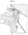
- the improvement of the invention can be applied to a coating head with a structure different from the one described, for example, on a coating head of the type shown in figure 4.
- Some of the elements of the head have a shape and/or a structure different from the corresponding elements of the head of figure 1; the corresponding elements have been indicated with the same reference numerals in both cases.
- the chamber 15 for the suspension has a simpler shape than that of the head of figure 1 and the deflector plate 13 is directly mobile on the oscillating frame 10, while the only function of the beam 9 is to block the blade 5 with the extremity projection 32; moreover, the feeding line 18 to the chamber 15 is, in this case, defined between the beam 9 and the oscillating frame 10.
Landscapes
- Coating Apparatus (AREA)
- Paper (AREA)
Abstract
Description
- The present invention relates to a coating head which is part of a coating machine and which is fit for applying a layer of coating suspension on a continuous paper sheet transported by a rotating cylinder.
- A head of this type substantially comprises an elastic blade which is thrust against the sheet and the function of which is to form said coating suspension layer and a chamber for containing the suspension: apart from other elements of the head, said chamber is delimited by said blade and by a portion of the outer surface of the cylinder and communicates with a feeding line through which the suspension is pressurized to the chamber.
- Moreover, said chamber is delimited by a deflector plate the position of which, in relation to the cylinder, can be adjusted so as to define, between said deflector plate and the surface of the cylinder, a suitably-sectioned exhaust port for the suspension.
- During the rotation of the cylinder, the outer surface of the paper sheet is brought into contact with the coating suspension contained in the aforedescribed chamber, while the extremity of the elastic blade operates a buttering of the suspension, so as to generate a layer of suspension of predetermined thickness on said surface. Therefore, a certain recirculation of coating suspension takes place in the suspension being discharged from the chamber through the aforedescribed exhaust port. A coating apparatus of this type, according to the preamble of claim 1, is disclosed in GB-A-2107222.
- The rotating heads of the type briefly described present some drawbacks.
- Above all, in many cases, the surface of the coating obtained on the sheet turns out to be uneven: printing defects are often found on sheets showing said drawback.
- Besides, with the heads of the aforedescribed type, the surface of the cylinder can easily get damaged, particularly in case of a sudden break of the sheet; in that case, the extreme edge of the deflector plate can actually come into contact with the surface of the cylinder.
- Finally, the flow rate of the suspension discharged from said chamber through the relative exhaust port can be excessively high, generating an excessive recirculation ratio of the suspension; this is mainly due to the fact that the extreme edge of the deflector plate has to be placed at a rather high distance from the surface of the cylinder in order to avoid, in particular working conditions of the coating head, the interference between said edge and surface.
- The object of the present invention is to provide a coating head of the type briefly described with which the drawbacks mentioned before can be eliminated and, therefore, a head which is fit for providing substantially even coating layers, which does not cause damages to the cylinder in case of a break of the sheet and from which the flow rate of the suspension discharged is low.
- Another object of the present invention is to provide a coating head of the type described with which high suspension pressures can be obtained in the chamber defined before.
- To achieve this, the coating apparatus of the invention is characterized by the features claimed in the characterizing part of claim 1. Pursuant to the principles of the present invention, the deflector plate is provided with a blocking element which can be elastically deformed and fit for limiting the passage of the suspension through the exhaust port, the element presenting a free edge facing the cylinder which is parallel to the cylinder axis, and the blocking element is placed on the deflector plate so that the distance between the free edge of the element and the surface of the cylinder is comprised between 0 and 4 mm.
- Advantageous embodiments of the invention are claimed in the subclaims.
- The structure of the coating head of the present invention will be more apparent from the description of two particular embodiments thereof given hereafter by way of example, with reference to the accompanying drawings in which:
- Figure 1 is a section of the main elements of the coating head according to the invention, corresponding to a first embodiment of the latter,
- Figure 2 shows a detail, to an enlarged scale, of some of the elements of the head of figure 1,
- Figure 3 is a detail similar to the one of figure 2 in which the elements have a shape different from that of the elements of figure 2,
- Figure 4 is a section of the main elements of another embodiment of the coating head according to the invention. The coating head of the invention, which can be part of an installation for the making of a continuous paper sheet, substantially comprises a rotating cylinder 1 on the outer surface of which a
continuous paper sheet 2 rests, said sheet being transported by the cylinder during its rotation. Besides, the head comprises acasing 3 to which there is fixed asupport 4 fit for holding up anelastic blade 5 which is thrust against thesheet 2 by an air bearing 6 carried by ablock 7, adjustable, by means of ascrew mechanism 8, on thesupport 4. The air bearing 6 substantially comprises a conduit made of a material which can be deformed, for example of rubber, within which compressed air can be supplied. - A
frame 10, which is oscillating in relation to thecasing 3, carries abeam 9 the longitudinal axis of which is parallel to the axis of the cylinder 1; said beam presents a first tongue 11 fit for pressing on the lower part of theblade 5 to block it in relation to thesupport 4 and a second tongue 12 interposed between the first one and the surface of the cylinder 1. - Besides, a
deflector plate 13, the longitudinal axis of which is also parallel to the axis of the cylinder 1, is mobile on thebeam 9 and its position can be adjusted in relation to the cylinder; to this end, said plate is connected toarms 14 operated, in their turn, by suitable actuators (not shown). - A
chamber 15 fit for containing a coating suspension is defined by the elements described before and is delimited, substantially, by theportion 16 of the outer surface of the cylinder 1, by the inner surface of theblade 5 and by the surfaces 17 of the tongues 11, 12 and of thebeam 9. Moreover, said chamber is delimited by thedeflector plate 13. - The
chamber 15 communicates, through afeeding line 18 provided in the tongue 11, with acoating suspension collection 19 into which said suspension is sent by means of appropriate means (not shown); moreover, thechamber 15 communicates with the exhaust through theexhaust port 20 from which the suspension runs on anappropriate deflector plate 23. - According to the invention, the
deflector plate 13 is provided with a blockingelement 24 which can be elastically deformed and fit for limiting the passage of the coating suspension through theexhaust port 20; said element presents afree edge 25, facing the cylinder 1, which is parallel to the cylinder axis (figure 2). - The blocking
element 24 is placed on thedeflector plate 13 so that the distance between thefree edge 25 and the surface of the cylinder 1 is comprised between 0 and 4 mm. Said element is conveniently made of rubber or of an elastomer material. It is long and presents sections perpendicular to its longitudinal axis having the same shape and dimensions; said sections can be of the type shown in figure 2 and, therefore; comprise apart 26 substantially ring-shaped, or said sections can be substantially rectangular as shown in the embodiment of figure 3. Besides, the blocking element can conveniently present a longitudinalinner cavity 27 so that the element can be deformed more easily. Said element can be fixed to thedeflector plate 13, as shown in Figure 2, housing anextremity part 28 of the element within anappropriate groove 29. Moreover, between theextreme edge 28 of theblocking element 24 and thegroove 29, there can be interposedappropriate plates 30. - It is apparent that the blocking
element 24 can be of any section provided it can generate anedge 25 parallel to the axis of the cylinder 1 and is able to cooperate with the surface of the cylinder as will be described hereinafter. - The coating head described operates in the following way. During the rotation of the cylinder 1, the
paper sheet 2 is brought into contact with the coating suspension contained within thechamber 15; therefore, the suspension adheres to the outer surface of the sheet and is buttered on it and conveniently smoothed by the action of the extremity of theelastic blade 5; in this way, on the sheet which is downstream of the blade, there is formed alayer 33 of the appropriate thickness, according to the force with which the blade is thrust against the cylinder 1. - During the rotation of the cylinder, there takes place a certain recirculation of the coating suspension within the
chamber 15, said suspension being supplied by thefeeding line 18 and discharged through theexhaust port 20. It has been noticed that when the coating head is provided with the blockingelement 24, the coating layer is deprived of the defects that were noticed when using coating heads without said element. - Actually, the layer obtained with the head according to the invention presents a surface and a thickness substantially even; this favorable result is due to the fact that within the
chamber 15 there are rather high pressures of the coating suspension, much higher than those noticed in the previous coating heads. This can be explained through the action operated by the blockingelement 24 which noticeably reduces the losses of suspension through theexhaust port 20. Actually, the blockingelement 24 is deformed according to the pressures which are transmitted to it by the coating suspension and, therefore, the section of theexhaust port 20 can be adjusted as required by suitably choosing the resistance of theblocking element 24. - Besides, it has been noticed that, in case of a sudden break of the
sheet 2, no damages are caused to the cylinder 1; actually, in that case, the blockingelement 24 operates an effective protective action by preventing the upper edge of thedeflector plate 13 from coming into contact with the surface of the cylinder and damaging it. - Moreover, the flow rate of the suspension discharged through the
exhaust port 20 is very low and much lower than the one noticed with the heads of the previous type; as a result, the recirculation of the suspension within thechamber 15 can be noticeably reduced. - Finally, the coating head in accordance with the invention can operate with rather high coating suspension pressures within the
chamber 15; here again, this favorable result depends on the presence of the blockingelement 24 which prevents the pressure from suddenly dropping at theexhaust port 20. Actually, it has been noticed that the values of the pressures within thechamber 15 can be three times higher than those obtained in the coating heads of the previous type. The possibility to operate with higher pressures within thechamber 15, and not very different from those in themain feed line 18, enables to obtain better working conditions. It has also been noticed that the best results are obtained when the distance between thefree edge 25 and the surface at the cylinder 1 is comprised within the range previously mentioned (0-4 mm). - It is apparent that the improvement of the invention can be applied to a coating head with a structure different from the one described, for example, on a coating head of the type shown in figure 4. Some of the elements of the head have a shape and/or a structure different from the corresponding elements of the head of figure 1; the corresponding elements have been indicated with the same reference numerals in both cases. In particular, the
chamber 15 for the suspension has a simpler shape than that of the head of figure 1 and thedeflector plate 13 is directly mobile on theoscillating frame 10, while the only function of thebeam 9 is to block theblade 5 with theextremity projection 32; moreover, thefeeding line 18 to thechamber 15 is, in this case, defined between thebeam 9 and theoscillating frame 10. - It is apparent that modifications, either of shape or arrangement of the different parts, can be made to the embodiment described in accordance with the present invention provided they do not leave the scope of the appended claims.
Claims (7)
- A coating apparatus having a rotating cylinder (1) and a coating head for applying a coating suspension layer on a continuous paper sheet (2) transported by said rotating cylinder (1), said head comprising an elastic blade (5) thrust against said sheet (2) and a chamber (15) fit for containing a coating suspension which is delimited by a portion (16) of the outer surface of said cylinder (1) and by said blade (5) and communicating with a feeding line (18) of said coating suspension, moreover said chamber (15) being delimited by a deflector plate (13), the position of which, in relation to said cylinder (1), can be adjusted so as to define between said plate (13) and said surface of the cylinder (1) an exhaust port (20) for said coating suspension,
characterized in that said deflector plate (13) is provided with a blocking element (24) which can be elastically deformed and fit for limiting the passage of said suspension through said exhaust port (20), said element (24) presenting a free edge (25) facing said cylinder (1) which is parallel to the cylinder axis, and
in that the blocking element (24) is placed on said deflector plate (13) so that the distance between said free edge (25) of said element (24) and said surface of said cylinder (1) is comprised between 0 and 4 mm. - The coating apparatus as claimed in claim 1, characterized in that said blocking element (24) is made of an elastomer material.
- The coating apparatus as claimed in claim 1, characterized in that said blocking element (24) is long and presents sections perpendicular to its longitudinal axis having the same shape and dimensions.
- The coating apparatus as claimed in claim 3, characterized in that said sections are substantially rectangular.
- The coating apparatus as claimed in claim 1, characterized in that said blocking element (24) presents a longitudinal inner cavity (27).
- The coating apparatus as claimed in claim 3, characterized in that said sections of said blocking element (24) comprise a part (26) substantially ring-shaped.
- The coating apparatus as claimed in claim 1, in which said deflector plate (13) presents an edge facing said cylinder (1) which is parallel to the cylinder axis, characterized in that said edge is provided with a groove (29) fit for housing a part (28) of said blocking element (24).
Applications Claiming Priority (3)
| Application Number | Priority Date | Filing Date | Title |
|---|---|---|---|
| IT67115A IT1241179B (en) | 1990-02-16 | 1990-02-16 | COATING HEAD SUITABLE FOR APPLYING A COATING SUSPENSION LAYER ON A CONTINUOUS SHEET OF PAPER. |
| IT6711590 | 1990-02-16 | ||
| PCT/US1991/001085 WO1991012373A1 (en) | 1990-02-16 | 1991-02-19 | Coating head for applying a coating suspension layer on a paper sheet |
Publications (2)
| Publication Number | Publication Date |
|---|---|
| EP0515534A1 EP0515534A1 (en) | 1992-12-02 |
| EP0515534B1 true EP0515534B1 (en) | 1995-01-11 |
Family
ID=11299701
Family Applications (1)
| Application Number | Title | Priority Date | Filing Date |
|---|---|---|---|
| EP91905004A Expired - Lifetime EP0515534B1 (en) | 1990-02-16 | 1991-02-19 | Coating head for applying a coating suspension layer on a paper sheet |
Country Status (9)
| Country | Link |
|---|---|
| US (1) | US5109792A (en) |
| EP (1) | EP0515534B1 (en) |
| JP (1) | JPH0817986B2 (en) |
| AU (1) | AU646845B2 (en) |
| CA (1) | CA2075893C (en) |
| DE (1) | DE69106695T2 (en) |
| IT (1) | IT1241179B (en) |
| PL (1) | PL53580Y1 (en) |
| WO (1) | WO1991012373A1 (en) |
Families Citing this family (6)
| Publication number | Priority date | Publication date | Assignee | Title |
|---|---|---|---|---|
| DE4130118C2 (en) * | 1991-09-11 | 1995-04-20 | Jagenberg Ag | Device for coating a web of material guided around a counter roller, in particular a paper or cardboard web |
| DE4208897C2 (en) * | 1992-03-19 | 1995-02-23 | Voith Gmbh J M | Applicator for coating webs of paper or cardboard |
| DE19532388C1 (en) * | 1995-09-01 | 1996-12-19 | Voith Sulzer Papiermasch Gmbh | Appts for coating moving paper or cardboard web |
| EP0761877A3 (en) * | 1995-09-06 | 1997-06-25 | Voith Sulzer Papiermasch Gmbh | Device for applying directly or indirectly fluid or pasty material onto a moving web, in particular paper or board |
| JP4711495B2 (en) | 2000-08-08 | 2011-06-29 | スリーエム イノベイティブ プロパティズ カンパニー | Coating device |
| ITBO20110708A1 (en) * | 2011-12-14 | 2013-06-15 | Marchesini Group Spa | APPARATUS FOR ADJUSTING THE RELEASE OF TABLETS IN THE HOLLOWS OF A THERMOFORMED TAPE |
Family Cites Families (10)
| Publication number | Priority date | Publication date | Assignee | Title |
|---|---|---|---|---|
| US4369731A (en) * | 1981-09-02 | 1983-01-25 | Consolidated Papers, Inc. | Coating apparatus having an internal leveling blade |
| US4405661A (en) * | 1981-09-10 | 1983-09-20 | Beloit Corporation | Blade type fountain coater and method |
| US4387663A (en) * | 1981-10-07 | 1983-06-14 | Beloit Corporation | Blade type fountain coater metering device |
| US4534309A (en) * | 1983-11-17 | 1985-08-13 | Consolidated Papers, Inc. | Paper coating apparatus |
| DE8400325U1 (en) * | 1984-01-07 | 1985-07-18 | Jagenberg AG, 4000 Düsseldorf | Device for coating material webs running over a support roller with adjustable application thickness |
| JPS6139866A (en) * | 1984-07-27 | 1986-02-26 | Mitsubishi Electric Corp | Inverter |
| AT394668B (en) * | 1984-11-17 | 1992-05-25 | Voith Gmbh J M | DEVICE FOR COATING CONTINUOUS GOODS WITH A COATING MEASUREMENT |
| US4780336A (en) * | 1987-04-06 | 1988-10-25 | Consolidated Papers, Inc. | Doctor blade for paper coater |
| DE3725545A1 (en) * | 1987-08-01 | 1989-02-09 | Jagenberg Ag | DEVICE FOR COATING A MATERIAL RAIL |
| KR101903745B1 (en) | 2011-11-29 | 2018-10-05 | (주)아모레퍼시픽 | Composition for improving hair growth or preventing hair loss |
-
1990
- 1990-02-16 IT IT67115A patent/IT1241179B/en active IP Right Grant
-
1991
- 1991-02-14 PL PL101473U patent/PL53580Y1/en unknown
- 1991-02-19 US US07/657,573 patent/US5109792A/en not_active Expired - Lifetime
- 1991-02-19 JP JP3504733A patent/JPH0817986B2/en not_active Expired - Fee Related
- 1991-02-19 DE DE69106695T patent/DE69106695T2/en not_active Expired - Fee Related
- 1991-02-19 WO PCT/US1991/001085 patent/WO1991012373A1/en not_active Ceased
- 1991-02-19 AU AU73381/91A patent/AU646845B2/en not_active Ceased
- 1991-02-19 CA CA002075893A patent/CA2075893C/en not_active Expired - Fee Related
- 1991-02-19 EP EP91905004A patent/EP0515534B1/en not_active Expired - Lifetime
Also Published As
| Publication number | Publication date |
|---|---|
| CA2075893C (en) | 1996-10-22 |
| DE69106695D1 (en) | 1995-02-23 |
| DE69106695T2 (en) | 1995-05-18 |
| PL53580Y1 (en) | 1995-11-30 |
| IT9067115A0 (en) | 1990-02-16 |
| JPH0817986B2 (en) | 1996-02-28 |
| AU646845B2 (en) | 1994-03-10 |
| WO1991012373A1 (en) | 1991-08-22 |
| EP0515534A1 (en) | 1992-12-02 |
| IT1241179B (en) | 1993-12-29 |
| JPH05503740A (en) | 1993-06-17 |
| AU7338191A (en) | 1991-09-03 |
| CA2075893A1 (en) | 1991-08-17 |
| IT9067115A1 (en) | 1991-08-16 |
| US5109792A (en) | 1992-05-05 |
Similar Documents
| Publication | Publication Date | Title |
|---|---|---|
| US4367691A (en) | Apparatus for adjustment of the coating thickness in the coating of traveling webs | |
| US6682191B2 (en) | Vacuum drums for printing, and duplex printers | |
| GB2336377A (en) | Coating thickness control | |
| EP0881090A3 (en) | Rotary stencil printing machine | |
| AU646845B2 (en) | Coating head for applying a coating suspension layer on a paper sheet | |
| EP1437221A3 (en) | Device for adjusting the contact pressure of an adjustably mounted cylinder | |
| EP0783977A3 (en) | Printing apparatus and method | |
| CA2214235A1 (en) | A vacuum apparatus having textured web-facing surface for controlling the rate of application of vacuum pressure in a through air drying papermaking process | |
| CA2214251A1 (en) | A vacuum apparatus having flow management device for controlling the rate of application of vacuum pressure in a through air drying papermaking process | |
| ATE195298T1 (en) | DEVICE FOR UNWINDING ROLLS OF WEB MATERIAL WITH A SYSTEM FOR REGULATING THE CONTACT PRESSURE | |
| EP0726849B1 (en) | Doctor blade clamping assembly for a printing press | |
| CA2175124A1 (en) | Device for Cleaning Cylindrical Surfaces in Rotary Printing Presses | |
| CA2013334A1 (en) | Method and apparatus for bonding continuous thin film to discrete base plates and film cutting apparatus therefor | |
| UA26307A (en) | SYSTEM OF PRINTING CYLIDERS OF A MACHINE FOR METALLOGRAPHIC PRINTING ON ROLLER MACHINES | |
| AU2001282069A1 (en) | Membrane pressure monitor sensor comprising a seal with a counter-deformation spring washer | |
| CA2254856A1 (en) | Printing mechanism | |
| US5809887A (en) | Ink duct of a rotary printing press | |
| JP3118586B2 (en) | Roller for ink supply in printing press | |
| JP4436465B2 (en) | Inkwell used for rotary printing press | |
| WO2002015237B1 (en) | Changing local compressibility of a wafer support member | |
| CA2294339A1 (en) | Method of operation of a printing unit and printing unit for offset machine | |
| AU4240097A (en) | A vacuum apparatus capable of controlling the rate of application of vacuum pressure in a through air drying papermaking process | |
| CA2174167A1 (en) | Apparatus for Preventing Condensation in Machines Processing a Web of Material | |
| Kellock | Built for speed | |
| TW353793B (en) | Semiconductor arrangement and method of producing the same |
Legal Events
| Date | Code | Title | Description |
|---|---|---|---|
| PUAI | Public reference made under article 153(3) epc to a published international application that has entered the european phase |
Free format text: ORIGINAL CODE: 0009012 |
|
| 17P | Request for examination filed |
Effective date: 19920807 |
|
| AK | Designated contracting states |
Kind code of ref document: A1 Designated state(s): DE FR GB IT SE |
|
| RAP1 | Party data changed (applicant data changed or rights of an application transferred) |
Owner name: BELOIT TECHNOLOGIES, INC. |
|
| 17Q | First examination report despatched |
Effective date: 19931012 |
|
| GRAA | (expected) grant |
Free format text: ORIGINAL CODE: 0009210 |
|
| AK | Designated contracting states |
Kind code of ref document: B1 Designated state(s): DE FR GB IT SE |
|
| ET | Fr: translation filed | ||
| REF | Corresponds to: |
Ref document number: 69106695 Country of ref document: DE Date of ref document: 19950223 |
|
| ITF | It: translation for a ep patent filed | ||
| PLBE | No opposition filed within time limit |
Free format text: ORIGINAL CODE: 0009261 |
|
| STAA | Information on the status of an ep patent application or granted ep patent |
Free format text: STATUS: NO OPPOSITION FILED WITHIN TIME LIMIT |
|
| 26N | No opposition filed | ||
| REG | Reference to a national code |
Ref country code: GB Ref legal event code: IF02 |
|
| PGFP | Annual fee paid to national office [announced via postgrant information from national office to epo] |
Ref country code: SE Payment date: 20080214 Year of fee payment: 18 Ref country code: DE Payment date: 20080219 Year of fee payment: 18 Ref country code: IT Payment date: 20080220 Year of fee payment: 18 Ref country code: GB Payment date: 20080220 Year of fee payment: 18 |
|
| PGFP | Annual fee paid to national office [announced via postgrant information from national office to epo] |
Ref country code: FR Payment date: 20080214 Year of fee payment: 18 |
|
| EUG | Se: european patent has lapsed | ||
| GBPC | Gb: european patent ceased through non-payment of renewal fee |
Effective date: 20090219 |
|
| REG | Reference to a national code |
Ref country code: FR Ref legal event code: ST Effective date: 20091030 |
|
| PG25 | Lapsed in a contracting state [announced via postgrant information from national office to epo] |
Ref country code: DE Free format text: LAPSE BECAUSE OF NON-PAYMENT OF DUE FEES Effective date: 20090901 |
|
| PG25 | Lapsed in a contracting state [announced via postgrant information from national office to epo] |
Ref country code: GB Free format text: LAPSE BECAUSE OF NON-PAYMENT OF DUE FEES Effective date: 20090219 Ref country code: FR Free format text: LAPSE BECAUSE OF NON-PAYMENT OF DUE FEES Effective date: 20090302 |
|
| PG25 | Lapsed in a contracting state [announced via postgrant information from national office to epo] |
Ref country code: IT Free format text: LAPSE BECAUSE OF NON-PAYMENT OF DUE FEES Effective date: 20090219 |
|
| PG25 | Lapsed in a contracting state [announced via postgrant information from national office to epo] |
Ref country code: SE Free format text: LAPSE BECAUSE OF NON-PAYMENT OF DUE FEES Effective date: 20090220 |