EP0515077A1 - Nozzle and valve assembly - Google Patents
Nozzle and valve assembly Download PDFInfo
- Publication number
- EP0515077A1 EP0515077A1 EP92304284A EP92304284A EP0515077A1 EP 0515077 A1 EP0515077 A1 EP 0515077A1 EP 92304284 A EP92304284 A EP 92304284A EP 92304284 A EP92304284 A EP 92304284A EP 0515077 A1 EP0515077 A1 EP 0515077A1
- Authority
- EP
- European Patent Office
- Prior art keywords
- piston
- cylinder
- fluid
- inlet
- nozzle
- Prior art date
- Legal status (The legal status is an assumption and is not a legal conclusion. Google has not performed a legal analysis and makes no representation as to the accuracy of the status listed.)
- Granted
Links
- 239000007788 liquid Substances 0.000 claims abstract description 19
- 239000012265 solid product Substances 0.000 claims abstract description 17
- 239000012530 fluid Substances 0.000 claims description 25
- 239000000047 product Substances 0.000 claims description 17
- 235000013305 food Nutrition 0.000 claims description 5
- 238000000034 method Methods 0.000 claims 5
- 239000007787 solid Substances 0.000 abstract description 5
- 239000012263 liquid product Substances 0.000 description 8
- 239000007789 gas Substances 0.000 description 4
- 230000001954 sterilising effect Effects 0.000 description 4
- 230000008878 coupling Effects 0.000 description 3
- 238000010168 coupling process Methods 0.000 description 3
- 238000005859 coupling reaction Methods 0.000 description 3
- 235000021055 solid food Nutrition 0.000 description 3
- 238000004659 sterilization and disinfection Methods 0.000 description 3
- IJGRMHOSHXDMSA-UHFFFAOYSA-N Atomic nitrogen Chemical compound N#N IJGRMHOSHXDMSA-UHFFFAOYSA-N 0.000 description 2
- 238000004140 cleaning Methods 0.000 description 2
- 238000010586 diagram Methods 0.000 description 2
- 235000013399 edible fruits Nutrition 0.000 description 1
- 239000011521 glass Substances 0.000 description 1
- 235000013372 meat Nutrition 0.000 description 1
- 239000002184 metal Substances 0.000 description 1
- 239000000203 mixture Substances 0.000 description 1
- 229910052757 nitrogen Inorganic materials 0.000 description 1
- 238000004806 packaging method and process Methods 0.000 description 1
- 239000011087 paperboard Substances 0.000 description 1
- 235000013547 stew Nutrition 0.000 description 1
- 235000013311 vegetables Nutrition 0.000 description 1
Images


Classifications
-
- B—PERFORMING OPERATIONS; TRANSPORTING
- B65—CONVEYING; PACKING; STORING; HANDLING THIN OR FILAMENTARY MATERIAL
- B65B—MACHINES, APPARATUS OR DEVICES FOR, OR METHODS OF, PACKAGING ARTICLES OR MATERIALS; UNPACKING
- B65B39/00—Nozzles, funnels or guides for introducing articles or materials into containers or wrappers
-
- B—PERFORMING OPERATIONS; TRANSPORTING
- B65—CONVEYING; PACKING; STORING; HANDLING THIN OR FILAMENTARY MATERIAL
- B65B—MACHINES, APPARATUS OR DEVICES FOR, OR METHODS OF, PACKAGING ARTICLES OR MATERIALS; UNPACKING
- B65B55/00—Preserving, protecting or purifying packages or package contents in association with packaging
- B65B55/02—Sterilising, e.g. of complete packages
Definitions
- This invention relates to a nozzle and valve assembly for supplying a product to each one of a series of containers.
- a device which is capable of supplying a predetermined amount of a product to each one of a series of containers.
- the product may be a mixture of a particulate solid product and a liquid.
- the device After a predetermined amount of product has been supplied to a container, there is the requirement for the device to provide a clean cut off of the supply of the product without supplying any extra product until supply is recommenced for supplying the next container.
- a nozzle and valve assembly comprising a cylinder having an open end, a first inlet leading into the interior of the cylinder, a second inlet, a piston having a free end and mounted for reciprocating movement in the cylinder at least between a first position and a second position, the piston permitting communication between the first inlet and the open end of the cylinder when the piston is in the first position, said free end of the piston moving past the first inlet as the piston moves from the first position to the second position so as to prevent communication between the first inlet and said open end of the cylinder, a fluid deflecting surface formed on said free end of the piston, means for directing fluid from the periphery of the fluid deflecting surface inwardly and on to the fluid deflecting surface when the piston is in the second position, and means for connecting the second inlet with the fluid directing means.
- a nozzle and valve assembly 100 for supplying a predetermined amount of a particulate solid product followed by a predetermined amount of a liquid product to each one of a series of containers.
- the containers may be, for example, metal cans, plastic pots, paperboard cartons or glass jars.
- the particulate solid product may be, for example, a food product such as, suitably sized, whole sliced or diced vegetables and pieces of meat in the form of a stew, or various fruits in a compote.
- the liquid product will be a liquid which is suitable for combining with the solid food product.
- the particulate solid product may also be a non-food product.
- the nozzle and valve assembly 100 may also be used to supply a particulate solid product on its own.
- the food product may be supplied to the containers after sterilization.
- the product may be supplied before sterilization and, in this case, the product may then be sterilized in the containers after they have been sealed.
- the nozzle and valve assembly 100 includes a cylinder 102 and a piston 104 mounted for reciprocating movement in cylinder 102.
- the cylinder 102 has a cylindrical bore 106 and the lower end of cylinder 102 is open.
- An aperture 110 is formed in the wall of cylinder 102 towards its lower end.
- the opening 110 serves as a first inlet and this inlet receives, in use, a solid particulate product.
- a coupling member 112 for connecting the aperture 110 to a supply pipe 114.
- a second aperture 118 is formed in the wall of cylinder 102.
- This aperture 118 provides a second inlet which receives a fluid in the form of a liquid product or a gas.
- aperture 118 is connected with a supply pipe 120.
- the aperture 118 is also connected to an internal bore 119 which leads from aperture 118 towards the bottom of cylinder 102.
- the lower end of cylinder 102 terminates with a thin walled annular section 124.
- the annular section 124 is enclosed within an annular end member 126.
- the external surface of the annular section 124 and the internal surface of the annular end member 126 together define an axially extending annular passage 128 and an inwardly directed annular orifice 130.
- the annular passage 128 is in communication with the bore 119. As will be explained later, the orifice 130 directs fluid inwardly.
- the cylinder 102 is closed by a cover 130 which receives a supply pipe 132.
- a supply pipe 132 receives a supply pipe 132.
- the deflecting surface 140 is conical and concave and is symmetrical with respect to a central axis 142.
- the piston 104 is provided with a rack 146 which engages a semi-circular gear wheel 148 mounted on a housing 150.
- the gear wheel 148 is rotated by a motor or other actuator, not shown, thereby causing the piston 104 to reciprocate within cylinder 102.
- annular seal 152 is received in a groove formed in piston 104.
- the assembly 100 is shown in a state for supplying a predetermined amount of particulate solid product to a container.
- the piston 104 is raised into a first position so that its free end is level with the top of aperture 110.
- the solid food product passes the free end of piston 104, a portion of it may adhere to this free end.
- the deflecting surface 140 on the free end is conical and concave, it approximates to the form that sticky solids would naturally take up on the end of a piston. Consequently, the mass of solids which actually adhere to the free end of the piston will be minimal.
- the piston 104 descends, thereby closing off the inlet 110, until it reaches its second position as shown in Figure 2. In this second position, the free end of piston 104 is level with the bottom end of the annular section 124 of cylinder 102. When the piston 104 is in this second position, the assembly 100 is in a state for supplying liquid to the container.
- a predetermined amount of liquid may be supplied under pressure from a metering valve through supply pipe 120.
- the liquid passes through the aperture 118, bore 119, annular passage 128 and orifice 130.
- the orifice 130 directs the liquid inwardly and onto the fluid deflecting surface 140.
- the deflecting surface 140 progressively deflects the liquid downwardly so as to form it into a smooth slow flowing column of liquid. Because the liquid is formed into a column in this manner, air entrainment is avoided.
- liquid is prevented from flowing through the orifice 130 by surface tension. Thus, a clean cut-off is obtained and no drips of liquid fall from the assembly 100 between containers.
- the liquid passes over the fluid deflecting surface 140, it washes away any solid product which has adhered thereto.
- the assembly shown in Figures 1 to 3 is also suitable for supplying only a predetermined amount of a particulate solid product to each container and without the supply of any liquid product.
- the supply pipe 120 is connected through a valve to a source of a gas.
- the gas may be , for example, air, steam or nitrogen. Then, when the valve 104 is in the lower position shown in Figure 2, the valve is opened for a short period with the result that the gas is directed on to the fluid deflecting surface 140 and thereby blows any solids which have adhered thereto downwards into a container.
- the piston 104 When the assembly 100 is not supplying either a particulate solid product or a liquid product, the piston 104 may be retracted slightly upwardly from the position shown in Figure 2.
- FIG. 3 shows the position adopted by the piston 104 when it is desired to clean the assembly.
- a sterilizing fluid such as steam
- the supply pipes 114, 120 and 132 can pass through the upper part of cylinder 102 and into the interior of housing 150. It can also flow past the seal 152 and the outer surface of the lower part of piston 104 so that it is discharged through the open end of cylinder 102.
- a return pipe 154 for the cleaning fluids is connected to the lower end of the cylinder 102 by a coupling member 156.
- the coupling member 156 includes a valve for containing pressure.
- FIG 4 there is shown a block diagram of the assembly 100 together with a supply pipe 161 for a particulate solid product and a supply pipe 160 for a liquid product.
- the supply pipes 160,161 are connected through respective metering valves 162,163 to the supply pipes 120,114.
- the assembly 100 is shown supplying products to a container 164.
- the metering valves 162,163 of Figure 4 may take the form shown in published European patent application EP-A-0 280 537 or unpublished European patent application 91 311 686.9.
Landscapes
- Engineering & Computer Science (AREA)
- Mechanical Engineering (AREA)
- Basic Packing Technique (AREA)
- Nozzles (AREA)
- Closures For Containers (AREA)
- Containers And Packaging Bodies Having A Special Means To Remove Contents (AREA)
- Supply Of Fluid Materials To The Packaging Location (AREA)
- Feeding, Discharge, Calcimining, Fusing, And Gas-Generation Devices (AREA)
Abstract
Description
- This invention relates to a nozzle and valve assembly for supplying a product to each one of a series of containers.
- In the packaging industry, there is a general requirement for a device which is capable of supplying a predetermined amount of a product to each one of a series of containers. The product may be a mixture of a particulate solid product and a liquid. After a predetermined amount of product has been supplied to a container, there is the requirement for the device to provide a clean cut off of the supply of the product without supplying any extra product until supply is recommenced for supplying the next container.
- It is an object of this invention to provide a nozzle for use in supplying predetermined amounts of a product and which meets the requirements set out above.
- According to this invention, there is provided a nozzle and valve assembly comprising a cylinder having an open end, a first inlet leading into the interior of the cylinder, a second inlet, a piston having a free end and mounted for reciprocating movement in the cylinder at least between a first position and a second position, the piston permitting communication between the first inlet and the open end of the cylinder when the piston is in the first position, said free end of the piston moving past the first inlet as the piston moves from the first position to the second position so as to prevent communication between the first inlet and said open end of the cylinder, a fluid deflecting surface formed on said free end of the piston, means for directing fluid from the periphery of the fluid deflecting surface inwardly and on to the fluid deflecting surface when the piston is in the second position, and means for connecting the second inlet with the fluid directing means.
- This invention will now be described in more detail, by way of example, with reference to the drawings in which:
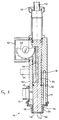
- Figure 1 is a longitudinal sectional view of a nozzle and valve assembly embodying this invention and showing the assembly in a state for supplying a solid product;
- Figure 2 is a longitudinal sectional view of the nozzle and valve assembly of Figure 1 showing the assembly in a state for supplying a liquid product;
- Figure 3 is a longitudinal sectional view of the nozzle and valve assembly of Figure 1 showing the assembly in a state in which it may be sterilized; and
- Figure 4 is a block diagram of the nozzle and valve assembly of Figure 1 connected to a supply pipe for a solid product and a metering valve for a liquid product.
- Referring now to Figures 1 to 3, there is shown a nozzle and
valve assembly 100 for supplying a predetermined amount of a particulate solid product followed by a predetermined amount of a liquid product to each one of a series of containers. The containers may be, for example, metal cans, plastic pots, paperboard cartons or glass jars. - The particulate solid product may be, for example, a food product such as, suitably sized, whole sliced or diced vegetables and pieces of meat in the form of a stew, or various fruits in a compote. In this case, the liquid product will be a liquid which is suitable for combining with the solid food product. The particulate solid product may also be a non-food product. The nozzle and
valve assembly 100 may also be used to supply a particulate solid product on its own. - Where the nozzle and
valve assembly 100 is used to supply a food product, the food product may be supplied to the containers after sterilization. Alternatively, the product may be supplied before sterilization and, in this case, the product may then be sterilized in the containers after they have been sealed. - The nozzle and
valve assembly 100 includes acylinder 102 and apiston 104 mounted for reciprocating movement incylinder 102. Thecylinder 102 has acylindrical bore 106 and the lower end ofcylinder 102 is open. - An
aperture 110 is formed in the wall ofcylinder 102 towards its lower end. Theopening 110 serves as a first inlet and this inlet receives, in use, a solid particulate product. On the outside ofcylinder 102, there is provided acoupling member 112 for connecting theaperture 110 to asupply pipe 114. - Above the
aperture 110 and at the rear of thecylinder 102 as shown in Figure 1, asecond aperture 118 is formed in the wall ofcylinder 102. Thisaperture 118 provides a second inlet which receives a fluid in the form of a liquid product or a gas. On the outside ofcylinder 102,aperture 118 is connected with asupply pipe 120. Theaperture 118 is also connected to aninternal bore 119 which leads fromaperture 118 towards the bottom ofcylinder 102. - The lower end of
cylinder 102 terminates with a thin walledannular section 124. Theannular section 124 is enclosed within anannular end member 126. The external surface of theannular section 124 and the internal surface of theannular end member 126 together define an axially extendingannular passage 128 and an inwardly directedannular orifice 130. Theannular passage 128 is in communication with thebore 119. As will be explained later, theorifice 130 directs fluid inwardly. - At its upper end, the
cylinder 102 is closed by acover 130 which receives asupply pipe 132. When theassembly 100 is used to supply a sterilized product, sterile air is supplied throughpipe 132 so as to keep the interior of the assembly in a sterile condition. - On the free end of the
piston 104, there is formed adeflecting surface 140. Thedeflecting surface 140 is conical and concave and is symmetrical with respect to acentral axis 142. - The
piston 104 is provided with arack 146 which engages asemi-circular gear wheel 148 mounted on ahousing 150. Thegear wheel 148 is rotated by a motor or other actuator, not shown, thereby causing thepiston 104 to reciprocate withincylinder 102. - Beneath the
rack 146, anannular seal 152 is received in a groove formed inpiston 104. - Referring now specifically to Figure 1, the
assembly 100 is shown in a state for supplying a predetermined amount of particulate solid product to a container. In this state, thepiston 104 is raised into a first position so that its free end is level with the top ofaperture 110. This permits solid food product to flow fromsupply pipe 114 throughbore 106 and to be discharged through the open end ofcylinder 102. As the solid food product passes the free end ofpiston 104, a portion of it may adhere to this free end. As thedeflecting surface 140 on the free end is conical and concave, it approximates to the form that sticky solids would naturally take up on the end of a piston. Consequently, the mass of solids which actually adhere to the free end of the piston will be minimal. - After the predetermined amount of the solid product has been supplied to the container, the
piston 104 descends, thereby closing off theinlet 110, until it reaches its second position as shown in Figure 2. In this second position, the free end ofpiston 104 is level with the bottom end of theannular section 124 ofcylinder 102. When thepiston 104 is in this second position, theassembly 100 is in a state for supplying liquid to the container. - With the
piston 104 in the position shown in Figure 2, a predetermined amount of liquid may be supplied under pressure from a metering valve throughsupply pipe 120. The liquid passes through theaperture 118, bore 119,annular passage 128 andorifice 130. Theorifice 130 directs the liquid inwardly and onto thefluid deflecting surface 140. Thedeflecting surface 140 progressively deflects the liquid downwardly so as to form it into a smooth slow flowing column of liquid. Because the liquid is formed into a column in this manner, air entrainment is avoided. When a predetermined amount of liquid has been supplied, liquid is prevented from flowing through theorifice 130 by surface tension. Thus, a clean cut-off is obtained and no drips of liquid fall from theassembly 100 between containers. As the liquid passes over thefluid deflecting surface 140, it washes away any solid product which has adhered thereto. - Where it is desired to supply a relatively large amount of liquid to each container, some of the liquid may be supplied while the
piston 104 is in the raised position as shown in Figure 1. - The assembly shown in Figures 1 to 3 is also suitable for supplying only a predetermined amount of a particulate solid product to each container and without the supply of any liquid product. Where solid product only is to be supplied, the
supply pipe 120 is connected through a valve to a source of a gas. The gas may be , for example, air, steam or nitrogen. Then, when thevalve 104 is in the lower position shown in Figure 2, the valve is opened for a short period with the result that the gas is directed on to thefluid deflecting surface 140 and thereby blows any solids which have adhered thereto downwards into a container. - When the
assembly 100 is not supplying either a particulate solid product or a liquid product, thepiston 104 may be retracted slightly upwardly from the position shown in Figure 2. - Figure 3 shows the position adopted by the
piston 104 when it is desired to clean the assembly. In this position, theseal 152 is raised above the bottom ofhousing 150. In order to sterilize the assembly, a sterilizing fluid, such as steam, is supplied to thesupply pipes supply pipe 132 can pass through the upper part ofcylinder 102 and into the interior ofhousing 150. It can also flow past theseal 152 and the outer surface of the lower part ofpiston 104 so that it is discharged through the open end ofcylinder 102. During cleaning, areturn pipe 154 for the cleaning fluids is connected to the lower end of thecylinder 102 by acoupling member 156. During sterilisation by steam, thecoupling member 156 includes a valve for containing pressure. - Referring now to Figure 4, there is shown a block diagram of the
assembly 100 together with asupply pipe 161 for a particulate solid product and asupply pipe 160 for a liquid product. The supply pipes 160,161 are connected through respective metering valves 162,163 to the supply pipes 120,114. In Figure 4, theassembly 100 is shown supplying products to acontainer 164. - By way of example, the metering valves 162,163 of Figure 4 may take the form shown in published European patent application EP-A-0 280 537 or unpublished European patent application 91 311 686.9.
Claims (8)
- A nozzle and valve assembly comprising a cylinder having an open end, a first inlet leading into the interior of the cylinder, a second inlet, a piston having a free end and mounted for reciprocating movement in the cylinder at least between a first position and a second position, the piston permitting communication between the first inlet and the open end of the cylinder when the piston is in the first position, said free end of the piston moving past the first inlet as the piston moves from the first position to the second position so as to prevent communication between the first inlet and said open end of the cylinder, a fluid deflecting surface formed on said free end of the piston, means for directing fluid from the periphery of the fluid deflecting surface inwardly and on to the fluid deflecting surface when the piston is in the second position, and means for connecting the second inlet with the fluid directing means.
- A nozzle and valve assembly as claimed in Claim 1, in which the fluid deflecting surface provided on said free end of the cylinder is conical and concave.
- A nozzle and valve assembly as claimed in Claim 1 or Claim 2, in which the fluid directing means includes an inwardly directed annular orifice which is arranged to direct fluid onto the fluid deflecting surface when the piston is in the second position.
- A nozzle and valve assembly as claimed in any one of Claims 1 to 3, in which said free end of the piston is adjacent said open end of the cylinder when the piston is in the second position.
- A method of supplying a particulate product to a container, said method comprising the steps of positioning a container beneath the open end of a nozzle and valve assembly as claimed in any one of Claims 1 to 4, supplying a particulate solid product to the first inlet of the assembly, moving the piston to the first position, moving the piston to the second position after a desired amount of the particulate solid product has been supplied to the container, and supplying a fluid to the first inlet with the piston still in the second position.
- A method as claimed in Claim 5, in which the particulate product is a food product.
- A method as claimed in Claim 6 or Claim 7, in which the fluid is a liquid.
- A method as claimed in Claim 6 or Claim 7, in which the fluid is a gas.
Applications Claiming Priority (2)
| Application Number | Priority Date | Filing Date | Title |
|---|---|---|---|
| GB9111266 | 1991-05-24 | ||
| GB919111266A GB9111266D0 (en) | 1991-05-24 | 1991-05-24 | A nozzle |
Publications (2)
| Publication Number | Publication Date |
|---|---|
| EP0515077A1 true EP0515077A1 (en) | 1992-11-25 |
| EP0515077B1 EP0515077B1 (en) | 1997-10-22 |
Family
ID=10695561
Family Applications (1)
| Application Number | Title | Priority Date | Filing Date |
|---|---|---|---|
| EP92304284A Expired - Lifetime EP0515077B1 (en) | 1991-05-24 | 1992-05-12 | Nozzle and valve assembly |
Country Status (7)
| Country | Link |
|---|---|
| US (1) | US5379921A (en) |
| EP (1) | EP0515077B1 (en) |
| JP (1) | JPH05193625A (en) |
| AT (1) | ATE159479T1 (en) |
| DE (1) | DE69222805T2 (en) |
| GB (1) | GB9111266D0 (en) |
| ZA (1) | ZA923605B (en) |
Cited By (2)
| Publication number | Priority date | Publication date | Assignee | Title |
|---|---|---|---|---|
| WO1996009957A2 (en) * | 1994-09-29 | 1996-04-04 | Tetra Laval Holdings & Finance S.A. | Packaging machine system for filling primary and secondary products into a container |
| US5687779A (en) * | 1992-09-17 | 1997-11-18 | Tetra Laval Holdings & Finance S.A. | Packaging machine system for filling primary and secondary products into a container |
Families Citing this family (1)
| Publication number | Priority date | Publication date | Assignee | Title |
|---|---|---|---|---|
| JP6120027B2 (en) * | 2015-10-01 | 2017-04-26 | 東洋製罐株式会社 | Filling equipment |
Citations (2)
| Publication number | Priority date | Publication date | Assignee | Title |
|---|---|---|---|---|
| GB1016620A (en) * | 1963-10-23 | 1966-01-12 | Kooperative Forbundet Ekonomis | Improvements in and relating to a drip-feed nozzle |
| GB1484763A (en) * | 1975-10-10 | 1977-09-08 | Scholle Corp | Filling device |
Family Cites Families (6)
| Publication number | Priority date | Publication date | Assignee | Title |
|---|---|---|---|---|
| US3132808A (en) * | 1961-02-20 | 1964-05-12 | Spra Flo Equipment Co Inc | Mixing apparatus |
| FR1482108A (en) * | 1966-04-04 | 1967-05-26 | Rhone Poulenc Sa | Device for improving the packaging of stringy and sticky products |
| NL7004874A (en) * | 1970-04-04 | 1971-10-06 | ||
| US4350187A (en) * | 1980-06-25 | 1982-09-21 | Pneumatic Scale Corporation | Filling machine |
| GB2089440B (en) * | 1980-12-16 | 1984-08-01 | Nestle Sa | Pump |
| US4460025A (en) * | 1982-01-29 | 1984-07-17 | Scholle William J | Filling valve assembly with fiber shearing edge |
-
1991
- 1991-05-24 GB GB919111266A patent/GB9111266D0/en active Pending
-
1992
- 1992-05-12 DE DE69222805T patent/DE69222805T2/en not_active Expired - Fee Related
- 1992-05-12 EP EP92304284A patent/EP0515077B1/en not_active Expired - Lifetime
- 1992-05-12 AT AT92304284T patent/ATE159479T1/en active
- 1992-05-18 ZA ZA923605A patent/ZA923605B/en unknown
- 1992-05-19 US US07/977,513 patent/US5379921A/en not_active Expired - Fee Related
- 1992-05-22 JP JP4156115A patent/JPH05193625A/en not_active Withdrawn
Patent Citations (2)
| Publication number | Priority date | Publication date | Assignee | Title |
|---|---|---|---|---|
| GB1016620A (en) * | 1963-10-23 | 1966-01-12 | Kooperative Forbundet Ekonomis | Improvements in and relating to a drip-feed nozzle |
| GB1484763A (en) * | 1975-10-10 | 1977-09-08 | Scholle Corp | Filling device |
Cited By (3)
| Publication number | Priority date | Publication date | Assignee | Title |
|---|---|---|---|---|
| US5687779A (en) * | 1992-09-17 | 1997-11-18 | Tetra Laval Holdings & Finance S.A. | Packaging machine system for filling primary and secondary products into a container |
| WO1996009957A2 (en) * | 1994-09-29 | 1996-04-04 | Tetra Laval Holdings & Finance S.A. | Packaging machine system for filling primary and secondary products into a container |
| WO1996009957A3 (en) * | 1994-09-29 | 1996-06-06 | Tetra Laval Holdings & Finance | Packaging machine system for filling primary and secondary products into a container |
Also Published As
| Publication number | Publication date |
|---|---|
| US5379921A (en) | 1995-01-10 |
| DE69222805T2 (en) | 1998-06-10 |
| JPH05193625A (en) | 1993-08-03 |
| ZA923605B (en) | 1993-09-16 |
| ATE159479T1 (en) | 1997-11-15 |
| EP0515077B1 (en) | 1997-10-22 |
| GB9111266D0 (en) | 1991-07-17 |
| DE69222805D1 (en) | 1997-11-27 |
Similar Documents
| Publication | Publication Date | Title |
|---|---|---|
| US6148874A (en) | Filling head mechanism that removes material from a spout of a filled container before completely disengaging from the spout | |
| JP2735329B2 (en) | Washing and cleaning system for packaging machines | |
| CA1288677C (en) | Process and device for aseptically filling a package | |
| US5758698A (en) | Fill system including a valve assembly and corresponding structure for reducing the mixing of product and air during container filling | |
| US5379921A (en) | Nozzle and valve assembly | |
| US5819821A (en) | Fill system including a flexible nozzle for reducing the mixing of product and air during container filling | |
| US5038548A (en) | Defoaming method and apparatus | |
| EP0257668B1 (en) | A method and an arrangement for the sterilization of a filter | |
| US5720326A (en) | Method and apparatus for filling a container with reduced mixing of product and air | |
| AU603166B2 (en) | A method and an arrangement for a filling valve in a packing machine | |
| CA1163610A (en) | Liquid filling and level sensing apparatus | |
| US5809739A (en) | Filling machine having a system to aid in cleaning exterior surfaces of cartons filled thereby | |
| US6941986B2 (en) | Device for aseptically filling containers | |
| JPH0794998B2 (en) | Liquid product weighing and dispensing equipment | |
| EP0781226B1 (en) | Packaging machine | |
| US6041576A (en) | Fill system for particulates | |
| CN88101078A (en) | The filling package method and apparatus | |
| EP3800132A1 (en) | A particle removal device for a filling machine | |
| MXPA97002391A (en) | Method for automatic draining of a product for a packaging machine | |
| EP0782526A1 (en) | Automated product draining method for a packaging machine | |
| WO1998005585A1 (en) | Flexible nozzle for reducing the mixing of product and air | |
| EP1812295B1 (en) | Apparatus and method for filling containers | |
| MXPA97002328A (en) | Apparatus for ventilation of tanks for an embased machine |
Legal Events
| Date | Code | Title | Description |
|---|---|---|---|
| PUAI | Public reference made under article 153(3) epc to a published international application that has entered the european phase |
Free format text: ORIGINAL CODE: 0009012 |
|
| 17P | Request for examination filed |
Effective date: 19920525 |
|
| AK | Designated contracting states |
Kind code of ref document: A1 Designated state(s): AT BE CH DE DK ES FR GB GR IT LI LU NL PT SE |
|
| RAP1 | Party data changed (applicant data changed or rights of an application transferred) |
Owner name: CARNAUDMETALBOX PLC |
|
| 17Q | First examination report despatched |
Effective date: 19940215 |
|
| RAP1 | Party data changed (applicant data changed or rights of an application transferred) |
Owner name: ODIN DEVELOPMENTS LIMITED |
|
| GRAG | Despatch of communication of intention to grant |
Free format text: ORIGINAL CODE: EPIDOS AGRA |
|
| GRAH | Despatch of communication of intention to grant a patent |
Free format text: ORIGINAL CODE: EPIDOS IGRA |
|
| GRAH | Despatch of communication of intention to grant a patent |
Free format text: ORIGINAL CODE: EPIDOS IGRA |
|
| GRAA | (expected) grant |
Free format text: ORIGINAL CODE: 0009210 |
|
| RAP1 | Party data changed (applicant data changed or rights of an application transferred) |
Owner name: ELOPAK A.S. |
|
| AK | Designated contracting states |
Kind code of ref document: B1 Designated state(s): AT BE CH DE DK ES FR GB GR IT LI LU NL PT SE |
|
| PG25 | Lapsed in a contracting state [announced via postgrant information from national office to epo] |
Ref country code: NL Free format text: LAPSE BECAUSE OF FAILURE TO SUBMIT A TRANSLATION OF THE DESCRIPTION OR TO PAY THE FEE WITHIN THE PRESCRIBED TIME-LIMIT Effective date: 19971022 Ref country code: LI Free format text: LAPSE BECAUSE OF FAILURE TO SUBMIT A TRANSLATION OF THE DESCRIPTION OR TO PAY THE FEE WITHIN THE PRESCRIBED TIME-LIMIT Effective date: 19971022 Ref country code: GR Free format text: LAPSE BECAUSE OF FAILURE TO SUBMIT A TRANSLATION OF THE DESCRIPTION OR TO PAY THE FEE WITHIN THE PRESCRIBED TIME-LIMIT Effective date: 19971022 Ref country code: ES Free format text: THE PATENT HAS BEEN ANNULLED BY A DECISION OF A NATIONAL AUTHORITY Effective date: 19971022 Ref country code: DK Free format text: LAPSE BECAUSE OF NON-PAYMENT OF DUE FEES Effective date: 19971022 Ref country code: CH Free format text: LAPSE BECAUSE OF FAILURE TO SUBMIT A TRANSLATION OF THE DESCRIPTION OR TO PAY THE FEE WITHIN THE PRESCRIBED TIME-LIMIT Effective date: 19971022 Ref country code: BE Free format text: LAPSE BECAUSE OF FAILURE TO SUBMIT A TRANSLATION OF THE DESCRIPTION OR TO PAY THE FEE WITHIN THE PRESCRIBED TIME-LIMIT Effective date: 19971022 Ref country code: AT Free format text: LAPSE BECAUSE OF FAILURE TO SUBMIT A TRANSLATION OF THE DESCRIPTION OR TO PAY THE FEE WITHIN THE PRESCRIBED TIME-LIMIT Effective date: 19971022 |
|
| REF | Corresponds to: |
Ref document number: 159479 Country of ref document: AT Date of ref document: 19971115 Kind code of ref document: T |
|
| REG | Reference to a national code |
Ref country code: CH Ref legal event code: EP |
|
| REF | Corresponds to: |
Ref document number: 69222805 Country of ref document: DE Date of ref document: 19971127 |
|
| ITF | It: translation for a ep patent filed | ||
| PG25 | Lapsed in a contracting state [announced via postgrant information from national office to epo] |
Ref country code: PT Free format text: LAPSE BECAUSE OF FAILURE TO SUBMIT A TRANSLATION OF THE DESCRIPTION OR TO PAY THE FEE WITHIN THE PRESCRIBED TIME-LIMIT Effective date: 19980122 |
|
| ET | Fr: translation filed | ||
| NLV1 | Nl: lapsed or annulled due to failure to fulfill the requirements of art. 29p and 29m of the patents act | ||
| REG | Reference to a national code |
Ref country code: CH Ref legal event code: PL |
|
| PG25 | Lapsed in a contracting state [announced via postgrant information from national office to epo] |
Ref country code: LU Free format text: LAPSE BECAUSE OF NON-PAYMENT OF DUE FEES Effective date: 19980512 |
|
| PLBE | No opposition filed within time limit |
Free format text: ORIGINAL CODE: 0009261 |
|
| STAA | Information on the status of an ep patent application or granted ep patent |
Free format text: STATUS: NO OPPOSITION FILED WITHIN TIME LIMIT |
|
| 26N | No opposition filed | ||
| REG | Reference to a national code |
Ref country code: GB Ref legal event code: IF02 |
|
| PGFP | Annual fee paid to national office [announced via postgrant information from national office to epo] |
Ref country code: FR Payment date: 20040408 Year of fee payment: 13 |
|
| PGFP | Annual fee paid to national office [announced via postgrant information from national office to epo] |
Ref country code: GB Payment date: 20040415 Year of fee payment: 13 |
|
| PGFP | Annual fee paid to national office [announced via postgrant information from national office to epo] |
Ref country code: SE Payment date: 20040421 Year of fee payment: 13 |
|
| PGFP | Annual fee paid to national office [announced via postgrant information from national office to epo] |
Ref country code: DE Payment date: 20040422 Year of fee payment: 13 |
|
| PG25 | Lapsed in a contracting state [announced via postgrant information from national office to epo] |
Ref country code: IT Free format text: LAPSE BECAUSE OF NON-PAYMENT OF DUE FEES;WARNING: LAPSES OF ITALIAN PATENTS WITH EFFECTIVE DATE BEFORE 2007 MAY HAVE OCCURRED AT ANY TIME BEFORE 2007. THE CORRECT EFFECTIVE DATE MAY BE DIFFERENT FROM THE ONE RECORDED. Effective date: 20050512 Ref country code: GB Free format text: LAPSE BECAUSE OF NON-PAYMENT OF DUE FEES Effective date: 20050512 |
|
| PG25 | Lapsed in a contracting state [announced via postgrant information from national office to epo] |
Ref country code: SE Free format text: LAPSE BECAUSE OF NON-PAYMENT OF DUE FEES Effective date: 20050513 |
|
| PG25 | Lapsed in a contracting state [announced via postgrant information from national office to epo] |
Ref country code: DE Free format text: LAPSE BECAUSE OF NON-PAYMENT OF DUE FEES Effective date: 20051201 |
|
| EUG | Se: european patent has lapsed | ||
| GBPC | Gb: european patent ceased through non-payment of renewal fee |
Effective date: 20050512 |
|
| PG25 | Lapsed in a contracting state [announced via postgrant information from national office to epo] |
Ref country code: FR Free format text: LAPSE BECAUSE OF NON-PAYMENT OF DUE FEES Effective date: 20060131 |
|
| REG | Reference to a national code |
Ref country code: FR Ref legal event code: ST Effective date: 20060131 |