EP0514178A1 - Apparatus for analyzing cells in urine - Google Patents
Apparatus for analyzing cells in urine Download PDFInfo
- Publication number
- EP0514178A1 EP0514178A1 EP92304371A EP92304371A EP0514178A1 EP 0514178 A1 EP0514178 A1 EP 0514178A1 EP 92304371 A EP92304371 A EP 92304371A EP 92304371 A EP92304371 A EP 92304371A EP 0514178 A1 EP0514178 A1 EP 0514178A1
- Authority
- EP
- European Patent Office
- Prior art keywords
- cell
- cells
- scattered
- light
- light intensity
- Prior art date
- Legal status (The legal status is an assumption and is not a legal conclusion. Google has not performed a legal analysis and makes no representation as to the accuracy of the status listed.)
- Granted
Links
Images


Classifications
-
- G—PHYSICS
- G01—MEASURING; TESTING
- G01N—INVESTIGATING OR ANALYSING MATERIALS BY DETERMINING THEIR CHEMICAL OR PHYSICAL PROPERTIES
- G01N15/00—Investigating characteristics of particles; Investigating permeability, pore-volume, or surface-area of porous materials
- G01N15/10—Investigating individual particles
- G01N15/14—Electro-optical investigation, e.g. flow cytometers
- G01N15/1456—Electro-optical investigation, e.g. flow cytometers without spatial resolution of the texture or inner structure of the particle, e.g. processing of pulse signals
-
- G—PHYSICS
- G01—MEASURING; TESTING
- G01N—INVESTIGATING OR ANALYSING MATERIALS BY DETERMINING THEIR CHEMICAL OR PHYSICAL PROPERTIES
- G01N21/00—Investigating or analysing materials by the use of optical means, i.e. using sub-millimetre waves, infrared, visible or ultraviolet light
- G01N21/62—Systems in which the material investigated is excited whereby it emits light or causes a change in wavelength of the incident light
- G01N21/63—Systems in which the material investigated is excited whereby it emits light or causes a change in wavelength of the incident light optically excited
- G01N21/64—Fluorescence; Phosphorescence
- G01N21/6428—Measuring fluorescence of fluorescent products of reactions or of fluorochrome labelled reactive substances, e.g. measuring quenching effects, using measuring "optrodes"
- G01N2021/6439—Measuring fluorescence of fluorescent products of reactions or of fluorochrome labelled reactive substances, e.g. measuring quenching effects, using measuring "optrodes" with indicators, stains, dyes, tags, labels, marks
-
- G—PHYSICS
- G01—MEASURING; TESTING
- G01N—INVESTIGATING OR ANALYSING MATERIALS BY DETERMINING THEIR CHEMICAL OR PHYSICAL PROPERTIES
- G01N21/00—Investigating or analysing materials by the use of optical means, i.e. using sub-millimetre waves, infrared, visible or ultraviolet light
- G01N21/17—Systems in which incident light is modified in accordance with the properties of the material investigated
- G01N21/47—Scattering, i.e. diffuse reflection
-
- G—PHYSICS
- G01—MEASURING; TESTING
- G01N—INVESTIGATING OR ANALYSING MATERIALS BY DETERMINING THEIR CHEMICAL OR PHYSICAL PROPERTIES
- G01N33/00—Investigating or analysing materials by specific methods not covered by groups G01N1/00 - G01N31/00
- G01N33/48—Biological material, e.g. blood, urine; Haemocytometers
- G01N33/483—Physical analysis of biological material
- G01N33/487—Physical analysis of biological material of liquid biological material
- G01N33/493—Physical analysis of biological material of liquid biological material urine
-
- Y—GENERAL TAGGING OF NEW TECHNOLOGICAL DEVELOPMENTS; GENERAL TAGGING OF CROSS-SECTIONAL TECHNOLOGIES SPANNING OVER SEVERAL SECTIONS OF THE IPC; TECHNICAL SUBJECTS COVERED BY FORMER USPC CROSS-REFERENCE ART COLLECTIONS [XRACs] AND DIGESTS
- Y10—TECHNICAL SUBJECTS COVERED BY FORMER USPC
- Y10S—TECHNICAL SUBJECTS COVERED BY FORMER USPC CROSS-REFERENCE ART COLLECTIONS [XRACs] AND DIGESTS
- Y10S209/00—Classifying, separating, and assorting solids
- Y10S209/939—Video scanning
Definitions
- This invention relates to an apparatus which uses flow cytometry to classify and enumerate cells such as leukocytes, erythrocytes, epithelial cells, casts and bacteria contained in urine.
- a screening test for kidney failure can be conducted based upon the presence of erythrocytes, leukocytes, epithelial cells, casts and bacteria in urine.
- Measurement of erythrocytes is important in terms of determining whether hemorrhage has occurred in the tract from the slomerulus to the urethra of the kidney.
- the appearance of leukocytes is considered to be a possible indication of a kidney disorder such as pyelonephritis, and detection thereof is important in early discovery of inflammation and infection.
- cast and erythrocyte morphology the origin of such inflammation and infection, namely the abnormal parts of the body, can be surmised.
- cell shall be used as a generic term for an erythrocyte, epithelial cell, cast and bacterium.
- Conventional methods of analyzing cells in urine include (a) visual examination based upon microscopy and (b) automatic measurement using a combination of a flat sheath flow and image processing technology.
- Method (a) involves centrifuging a urine specimen, preparing a slide sample of the matter of sediment and observing, classifying and counting cells under a microscope.
- Method (b) involves using a video camera to capture an image of a urine specimen made to flow as an extremely flat stream within a sheathing solution employed as an outer layer, and subjecting the still picture obtained to image processing, whereby the images of the cells in the specimen are extracted and displayed.
- the apparatus which uses method (b) is itself high in cost owing to reliance upon image processing, and the processing speed is low. Furthermore, the advantage of automation afforded by the apparatus of method (b) merely displays the images upon roughly classifying the imaged components based upon their size, and it is required that classification process be performed by a human being while the display is observed. Thus, the automatic classification and enumeration of cell components is not possible.
- Still another problem is that a number of some cells such as bacteria in urine clumps to form a large cell diameter, thus making it difficult to distinguish between a clumping group of bacteria and a blood cell.
- the present invention seeks to improve upon the foregoing shortcomings and its object is to provide an apparatus for analyzing cells in urine, in which a large quantity of a urine specimen can be analyzed using flow cytometry, the number of various cells (erythrocytes, leukocytes, epithelial cells, casts and bacteria, etc.) detected in the specimen can be greatly increased to enable more precise analysis of cells in urine, the process from drawing of the urine specimen into the apparatus to display of the analytical results can be fully automated to eliminate the need for any human intervention, the processing speed can be raised and the cost of the apparatus can be kept low.
- Fig. 1 is a block diagram showing the arrangement of the principal elements of an optical system embodying the present invention.
- the optical system includes a light source 1 constituted by an argon-ion laser at one end of the system, a flow cell 2, a condenser lens 5 provided between the light source 1 and the flow cell 2, a photomultiplier 6 at the other end of the system, a collector lens 7, a light shield 8, a dichroic mirror 9 and a filter 10 provided between the flow cell 2 and the photomultiplier 6, and a lens 12 provided between the dichroic mirror 9 and a photodiode 11.
- a urine specimen flows into the flow cell 2 from a nozzle 3 attached to the flow cell.
- Reference numeral 15 denotes a beam stopper.
- Fig. 2 is a block diagram illustrating the principal components of an electric circuit embodying the present invention.
- the circuitry of Fig. 2 is divided into a signal processing portion 19 and data processing portion 20.
- An output signal from the photodiode 11 is connected to an amplifier 21 in the signal processing portion 19, and the output of the amplifier 21 is connected to a DC (direct-current) restorer 22.
- the output of the DC restorer 22 is connected to a peak-hold circuit 23, the output of which is connected to an analog/digital converter circuit (hereinafter referred to simply as an "A/D converter") 24.
- A/D converter analog/digital converter circuit
- the output of the photomultiplier 6 is connected to an amplifier 25 in the signal processing portion 19, the output of which is connected to a DC (direct-current) restorer 27.
- the output of the latter is connected to a peak-hold circuit 28, the output of which is connected to an A/D (analog/digital) converter 29.
- a threshold circuit 30 is connected to a digital/analog converter circuit (hereinafter referred to simply as a "D/A converter") 31, the output of which is connected to the reference input of a comparator 32.
- the output of the DC restorer 22 is connected to the comparator 32 at its other input terminal, namely the terminal whose input is to be compared with the reference.
- the output of the comparator 32 is connected to a pulse-width counter 33, to which a clock signal output from a clock signal generating circuit 34 is applied as an input.
- the output of the DC restorer 22 is further connected to a differentiating circuit 47, whose output is connected to a peak counter 48.
- the output of the DC restorer 22 is connected also to a control circuit 35.
- the latter produces a control signal output connected to the A/D converters 24, 29, the peak counter 48 and the pulse-width counter 33.
- the outputs of the A/D converters 24, 29 and the outputs of the peak counter 48 and pulse-width counter 33 are connected to a control circuit 40 for controlling a read/write operation.
- a trigger signal T is connected to the control circuit 40 and a counter 41.
- a memory circuit 42 for storing data indicative of individual cells is connected to the control circuit 40.
- the memory circuit 42 is connected, via the control circuit 40, to a data analyzing circuit 43 which classifies and enumerates cells.
- the output of the counter 41 also is connected to the data analyzing circuit 43.
- a memory circuit 45 which stores the control program of the apparatus, cell-diameter conversion values, cell judgment values, etc., and a counter 46, which counts the number of each type of cell, are connected to the data analyzing circuit 43.
- Figs. 3 through 8 are flowcharts illustrating the operation of the electrical circuitry according to this embodiment. These flowcharts will be referred to later.
- the original solution of the urine specimen contains in admixture a first reagent containing a specific stain and a second reagent for stabilizing pH and osmotic pressure.
- the resulting urine specimen mixture containing the reagent is discharged from the nozzle 9, and a sheathed flow is formed by causing a sheathing solution to flow along the periphery of the urine stream.
- cells 13 erythrocytes, leukocytes, epithelial cells, casts and bacteria, etc.
- in the urine specimen flow in an ordered array such as in single file through a narrow zone at the central portion of the flow cell 2, as shown in Fig. 1.
- the laser light from the light source 1 is condensed by the condenser lens 5 so as to irradiate the narrow flow zone of the flow cell with an elliptical beam spot that is slender in the direction of flow and broad in the direction perpendicular to the flow direction.
- the present invention is directed toward measurement of cells in urine, namely components of urine sediment.
- the thickness of the narrow flow zone should be set to be comparatively small in comparison with the sizes of the cells.
- a suitable value for the minor axis of the ellipse is 1 - 20 ⁇ m. It will suffice to make the major axis of the ellipse large enough to fully extend across the width of the slender specimen stream in the narrow flow zone.
- the cells 13 in the slender specimen stream are irradiated with the laser light.
- Transmitted laser light which has passed through the flow cell intact without striking the cells is blocked by a beam stopper 15.
- Forward-scattered light and forward fluorescent light emitted from an irradiated cell at a narrow angle is condensed by the collector lens 7, and the condensed light passes through a pin hole 16 of the shield 8. Almost all of the forward-scattered light and forward fluorescent light thus emitted from the cell 13 arrives at the dichroic mirror 9.
- the fluorescent light the wavelength of which is greater than that of the scattered light, is transmitted intact by the dichroic mirror 9 at a high rate and stray light is removed by the filter 10, after which the fluorescent light is detected and converted into an electric signal by the photomultiplier 6, from which a forward fluorescent light signal is outputted. Meanwhile, the scattered light is reflected by the dichroic mirror 9 at a high rate, after which the light is condensed by the lens 12 and converted into an electric signal by the photodiode 11, from which a forward-scattered light signal is outputted.
- Output waveforms of the forward-scattered light signal from the photodiode 11 and output waveforms of the forward fluorescent-light signal from the photomultiplier 6 are as illustrated in the waveform diagrams of Figs. 9 through 13, in which time is plotted along the horizontal axis and voltage along the vertical axis.
- Fig. 11 shows the output waveform of a forward-scattered light signal from an epithelial cell and (b) shows an output waveform of a forward fluorescent-light signal from the epithelial cell.
- Epithelial cells exist in a wide variety of sizes from large to small, but they are small in thickness and possess a complicated shape and internal structure.
- a forward-scattered light signal S5 obtained exhibits a large width and a complicated waveform. Since the minor axis of the beam spot of the irradiating light is smaller than the diameter of an epithelial cell, the signal waveform obtained reflects the size, shape and internal structure of the cell.
Abstract

Description
- This invention relates to an apparatus which uses flow cytometry to classify and enumerate cells such as leukocytes, erythrocytes, epithelial cells, casts and bacteria contained in urine.
- Examination of urine content has long been carried out and is still of great importance. For example, a screening test for kidney failure can be conducted based upon the presence of erythrocytes, leukocytes, epithelial cells, casts and bacteria in urine. Measurement of erythrocytes is important in terms of determining whether hemorrhage has occurred in the tract from the slomerulus to the urethra of the kidney. The appearance of leukocytes is considered to be a possible indication of a kidney disorder such as pyelonephritis, and detection thereof is important in early discovery of inflammation and infection. Furthermore, by examining cast and erythrocyte morphology, the origin of such inflammation and infection, namely the abnormal parts of the body, can be surmised.
- In this specification, the word "cell" shall be used as a generic term for an erythrocyte, epithelial cell, cast and bacterium.
- Conventional methods of analyzing cells in urine include (a) visual examination based upon microscopy and (b) automatic measurement using a combination of a flat sheath flow and image processing technology.
- Method (a) involves centrifuging a urine specimen, preparing a slide sample of the matter of sediment and observing, classifying and counting cells under a microscope.
- Method (b), an example of which is disclosed in the specification of Japanese Patent Application Laid-Open (KOKAI) No. 57-500995 or USP 4,338,024, involves using a video camera to capture an image of a urine specimen made to flow as an extremely flat stream within a sheathing solution employed as an outer layer, and subjecting the still picture obtained to image processing, whereby the images of the cells in the specimen are extracted and displayed.
- However, both of the foregoing methods exhibit certain drawbacks. Specifically, method (a) which relies upon a microscope entails considerable labor for such pre-treatments as centrifugal separation and staining. In addition, cells may be damaged in the centrifuging process and there are disparities in concentration from one specimen to another.
- The apparatus which uses method (b) is itself high in cost owing to reliance upon image processing, and the processing speed is low. Furthermore, the advantage of automation afforded by the apparatus of method (b) merely displays the images upon roughly classifying the imaged components based upon their size, and it is required that classification process be performed by a human being while the display is observed. Thus, the automatic classification and enumeration of cell components is not possible.
- Further, since the amount of the urine specimen measured according to the methods (a) and (b) is very small, a drawback is that casts, the discovery of the presence of which is very important, cannot be discovered in the urine sediment. Specifically, the low frequency of the presence of cast in such that usually only several tens thereof are present per milliliter.
- Another problem is that since the types of components in urine sediment are numerous and differ widely in size from one specimen to another, and in view of the fact that the degree of cell damage can be considered to be large, it is understood that analysis of urine sediment is not possible using flow cytometry.
- Still another problem is that a number of some cells such as bacteria in urine clumps to form a large cell diameter, thus making it difficult to distinguish between a clumping group of bacteria and a blood cell.
- Accordingly, the present invention seeks to improve upon the foregoing shortcomings and its object is to provide an apparatus for analyzing cells in urine, in which a large quantity of a urine specimen can be analyzed using flow cytometry, the number of various cells (erythrocytes, leukocytes, epithelial cells, casts and bacteria, etc.) detected in the specimen can be greatly increased to enable more precise analysis of cells in urine, the process from drawing of the urine specimen into the apparatus to display of the analytical results can be fully automated to eliminate the need for any human intervention, the processing speed can be raised and the cost of the apparatus can be kept low.
- According to the present invention, the foregoing object is attained by providing an apparatus for analyzing cells in urine characterized in that scattered light and fluorescent light from individual cells in a urine specimen are detected by flow cytometry, data indicative of scattered-light intensity and data indicative of the number of peaks of scattered light is obtained from the scattered light, data indicative of fluorescent-light intensity is obtained from the fluorescent light, the scattered light is converted into pulse signals, and pulse width is converted into cell-diameter data in accordance with known cell diameters. The apparatus is further characterized in that actual-measurement data indicating the characteristics of each cell is stored in memory beforehand as cell judgment values, the data indicative of the detected cells is analyzed in accordance with these cell judgment values, and the cells contained in the urine are classified and enumerated automatically.
- Other features and advantages of the present invention will be apparent from the following description taken in conjunction with the accompanying drawings, in which like reference characters designate the same or similar parts throughout the figures thereof.
- Fig. 1 is a block diagram showing the arrangement of the principal elements of an optical system embodying the present invention;
- Fig. 2 is a block diagram illustrating the principal components of an electric circuit embodying the present invention;
- Fig. 3 is a flowchart illustrating operation of the embodiment;
- Fig. 4 is a flowchart illustrating an operation for analyzing erythrocytes according to the embodiment;
- Fig. 5 is a flowchart illustrating an operation for analyzing leukocytes according to the embodiment;
- Fig. 6 is a flowchart illustrating an operation for analyzing epithelial cells according to the embodiment;
- Fig. 7 is a flowchart illustrating an operation for analyzing casts according to the embodiment;
- Fig. 8 is a flowchart illustrating an operation for analyzing bacteria according to the embodiment;
- Fig. 9 is a waveform diagram in which (a) illustrates an output waveform of a forward-scattered light signal from an erythrocyte and (b) illustrates an output waveform of a forward fluorescent-light signal from the erythrocyte;
- Fig. 10 is a waveform diagram in which (a) illustrates an output waveform of a forward-scattered light signal from a leukocyte and (b) illustrates an output waveform of a forward fluorescent-light signal from the leukocyte;
- Fig. 11 is a waveform diagram in which (a) illustrates an output waveform of a forward-scattered light signal from an epithelial cell and (b) illustrates an output waveform of a forward fluorescent-light signal from the epithelial cell;
- Fig. 12 is a waveform diagram in which (a) illustrates an output waveform of a forward-scattered light signal from a bacterium and (b) illustrates an output waveform of a forward fluorescent-light signal from the bacterium;
- Fig. 13 is a waveform diagram in which (a) illustrates an output waveform of a forward-scattered light signal from a cast and (b) illustrates an output waveform of a forward fluorescent-light signal from the cast; and
- Fig. 14 illustrates scatter diagrams in which (a) is a scatter diagram of scattered-light intensity and fluorescent light intensity, (b) a scatter diagram of fluorescent light intensity and cell diameter, (c) a scatter diagram of scattered-light intensity and cell diameter, and (d) a scatter diagram of the number of scattered-light peaks and cell diameter.
- A preferred embodiment of an apparatus for analyzing cells in urine according to the present invention will now be described with reference to the drawings.
- Fig. 1 is a block diagram showing the arrangement of the principal elements of an optical system embodying the present invention. As shown in Fig. 1, the optical system includes a
light source 1 constituted by an argon-ion laser at one end of the system, aflow cell 2, acondenser lens 5 provided between thelight source 1 and theflow cell 2, aphotomultiplier 6 at the other end of the system, a collector lens 7, a light shield 8, adichroic mirror 9 and a filter 10 provided between theflow cell 2 and thephotomultiplier 6, and alens 12 provided between thedichroic mirror 9 and a photodiode 11. A urine specimen flows into theflow cell 2 from anozzle 3 attached to the flow cell.Reference numeral 15 denotes a beam stopper. - Fig. 2 is a block diagram illustrating the principal components of an electric circuit embodying the present invention.
- The circuitry of Fig. 2 is divided into a signal processing portion 19 and data processing portion 20. An output signal from the photodiode 11 is connected to an amplifier 21 in the signal processing portion 19, and the output of the amplifier 21 is connected to a DC (direct-current)
restorer 22. The output of theDC restorer 22 is connected to a peak-hold circuit 23, the output of which is connected to an analog/digital converter circuit (hereinafter referred to simply as an "A/D converter") 24. - The output of the
photomultiplier 6 is connected to anamplifier 25 in the signal processing portion 19, the output of which is connected to a DC (direct-current)restorer 27. The output of the latter is connected to a peak-hold circuit 28, the output of which is connected to an A/D (analog/digital)converter 29. - Further, a
threshold circuit 30 is connected to a digital/analog converter circuit (hereinafter referred to simply as a "D/A converter") 31, the output of which is connected to the reference input of acomparator 32. The output of theDC restorer 22 is connected to thecomparator 32 at its other input terminal, namely the terminal whose input is to be compared with the reference. The output of thecomparator 32 is connected to a pulse-width counter 33, to which a clock signal output from a clocksignal generating circuit 34 is applied as an input. The output of theDC restorer 22 is further connected to a differentiatingcircuit 47, whose output is connected to apeak counter 48. - The output of the
DC restorer 22 is connected also to acontrol circuit 35. The latter produces a control signal output connected to the A/D converters peak counter 48 and the pulse-width counter 33. - The outputs of the A/
D converters peak counter 48 and pulse-width counter 33 are connected to acontrol circuit 40 for controlling a read/write operation. A trigger signal T is connected to thecontrol circuit 40 and acounter 41. Amemory circuit 42 for storing data indicative of individual cells is connected to thecontrol circuit 40. Thememory circuit 42 is connected, via thecontrol circuit 40, to adata analyzing circuit 43 which classifies and enumerates cells. The output of thecounter 41 also is connected to thedata analyzing circuit 43. Amemory circuit 45 which stores the control program of the apparatus, cell-diameter conversion values, cell judgment values, etc., and acounter 46, which counts the number of each type of cell, are connected to thedata analyzing circuit 43. - Figs. 3 through 8 are flowcharts illustrating the operation of the electrical circuitry according to this embodiment. These flowcharts will be referred to later.
- The operation which characterizes the embodiment of the invention constructed as set forth above will now be described.
- The original solution of the urine specimen contains in admixture a first reagent containing a specific stain and a second reagent for stabilizing pH and osmotic pressure. The resulting urine specimen mixture containing the reagent is discharged from the
nozzle 9, and a sheathed flow is formed by causing a sheathing solution to flow along the periphery of the urine stream. As a consequence, cells 13 (erythrocytes, leukocytes, epithelial cells, casts and bacteria, etc.) in the urine specimen flow in an ordered array such as in single file through a narrow zone at the central portion of theflow cell 2, as shown in Fig. 1. The laser light from thelight source 1 is condensed by thecondenser lens 5 so as to irradiate the narrow flow zone of the flow cell with an elliptical beam spot that is slender in the direction of flow and broad in the direction perpendicular to the flow direction. - The present invention is directed toward measurement of cells in urine, namely components of urine sediment. In order to obtain more detailed information from the group of cells carried by urine, the thickness of the narrow flow zone should be set to be comparatively small in comparison with the sizes of the cells. As for the dimensions of the irradiating elliptical beam spot at the constricted portion of the specimen stream, a suitable value for the minor axis of the ellipse is 1 - 20 µm. It will suffice to make the major axis of the ellipse large enough to fully extend across the width of the slender specimen stream in the narrow flow zone.
- Thus, the cells 13 in the slender specimen stream are irradiated with the laser light. Transmitted laser light which has passed through the flow cell intact without striking the cells is blocked by a
beam stopper 15. Forward-scattered light and forward fluorescent light emitted from an irradiated cell at a narrow angle is condensed by the collector lens 7, and the condensed light passes through a pin hole 16 of the shield 8. Almost all of the forward-scattered light and forward fluorescent light thus emitted from the cell 13 arrives at thedichroic mirror 9. The fluorescent light, the wavelength of which is greater than that of the scattered light, is transmitted intact by thedichroic mirror 9 at a high rate and stray light is removed by the filter 10, after which the fluorescent light is detected and converted into an electric signal by thephotomultiplier 6, from which a forward fluorescent light signal is outputted. Meanwhile, the scattered light is reflected by thedichroic mirror 9 at a high rate, after which the light is condensed by thelens 12 and converted into an electric signal by the photodiode 11, from which a forward-scattered light signal is outputted. - Output waveforms of the forward-scattered light signal from the photodiode 11 and output waveforms of the forward fluorescent-light signal from the
photomultiplier 6 are as illustrated in the waveform diagrams of Figs. 9 through 13, in which time is plotted along the horizontal axis and voltage along the vertical axis. - In Fig. 9, (a) shows the output waveform of a forward-scattered light signal from an erythrocyte and (b) shows an output waveform of a forward fluorescent-light signal from the erythrocyte. Since erythrocytes are small in size and regular in shape, a forward-scattered light signal S₁ having a single peak is obtained. However, since an erythrocyte does not possess a nucleus, it cannot be stained by a stain and therefore fluorescent light S₂ is not detected.
- In Fig. 10, (a) shows the output waveform of a forward-scattered light signal from a leukocyte and (b) shows an output waveform of a forward fluorescent-light signal from the leukocyte. Leukocytes are large but are of the same size or slightly larger than erythrocytes, and a forward-scattered light signal S₃ similar to the forward-scattered light signal S₁ is detected. However, a forward fluorescent-light signal S₄ also is detected owing to the presence of a nucleus.
- In Fig. 11, (a) shows the output waveform of a forward-scattered light signal from an epithelial cell and (b) shows an output waveform of a forward fluorescent-light signal from the epithelial cell. Epithelial cells exist in a wide variety of sizes from large to small, but they are small in thickness and possess a complicated shape and internal structure. As a result, a forward-scattered light signal S₅ obtained exhibits a large width and a complicated waveform. Since the minor axis of the beam spot of the irradiating light is smaller than the diameter of an epithelial cell, the signal waveform obtained reflects the size, shape and internal structure of the cell. However, in comparison with the forward-scattered light signal S₁ of the erythrocyte and the forward-scattered light signal S₃ of the leukocyte, the forward-scattered light signal S₅ of the epithelial cell does not have a peak value which is that high in proportion to the large width of the signal. The reason for this is understood to be that since the cell thickness is small, all of the irradiating light is not scattered; i.e., some of it transmitted through the cell. Further, a forward fluorescent-light signal S₆ obtained also has a large width and a complicated waveform. The portion of the waveform at which signal strength is very high represents the location of the nucleus. Epithelial cells have a large amount of cytoplasm, which also emits a certain degree of fluorescence.
- In Fig. 12, (a) shows the output waveform of a forward-scattered light signal from a bacterium and (b) shows an output waveform of a forward fluorescent-light signal from the bacterium. Since bacteria are small in comparison with blood cells and the like, a small forward-scattered light signal S₇ and forward fluorescent-light signal S₈ are detected.
- In Fig. 13, (a) shows the output waveform of a forward-scattered light signal from a cast and (b) shows an output waveform of a forward fluorescent-light signal from the cast. Since a cast has a size on the order of one hundred to several hundred microns, a forward-scattered light signal S₉ and a forward fluorescent-light signal S₁₀ having a very large width are obtained.
- Thus, the
photomultiplier 6 produces a forward fluorescent-light signal for each of the variety of cells contained in the urine specimen. Each forward fluorescent-light signal is amplified by theamplifier 25 in the signal processing portion 19, and the amplified signal is applied to theDC restorer 27, which removes DC components and extracts the amplitude portion (namely the portion of the forward fluorescent-light signal). The resulting forward fluorescent-light signal from which the DC components have been removed is applied to the peak-hold circuit 28, which detects the peak value of the signal. The detected peak value is converted into a digital value by A/D converter 29, and this value is outputted as data indicative of the intensity of forward fluorescent light. - The photodiode 11 produces a forward-scattered light signal for each of the variety of cells contained in the urine specimen. Each forward-scattered light signal is amplified by the amplifier 21 in the signal processing portion 19, and the amplified signal is applied to the
DC restorer 22, which removes DC components and extracts the amplitude portion (namely the portion of the forward-scattered light signal). The resulting forward-scattered light signal from which the DC components have been removed is applied to the peak-hold circuit 23, which detects the peak value of the signal. The detected peak value is converted into a digital value by the A/D converter 24, and this value is outputted as data indicative of the intensity of forward-scattered light. Further, the forward-scattered light signal from which the DC components have been removed by theDC restorer 22 is differentiated by the differentiatingcircuit 47, so that a pulse signal is generated the number of peaks of which is based upon the sign of the differentiated signal. The number of peaks of the pulse signal is counted by thepeak counter 48. The latter outputs the count as data indicative of the number of scattered-light peaks. The forward-scattered light signal from which the DC components have been removed by theDC restorer 22 is applied also to the comparison input terminal of thecomparator 32. - In order to eliminate the effects of contaminants such as dust particles contained in the urine specimen, the
threshold circuit 30 is set beforehand to an appropriate threshold value. This value is converted into an analog value by the D/A circuit 31, and a voltage indicative of the analog value is applied to the reference input terminal of thecomparator 32. Only a forward-scattered light signal which exceeds the threshold value is outputted by thecomparator 32 in the form of square wave. The square-wave signal enters the pulse-width counter 33, which counts the clock signal from theclock signal generator 34 for the duration of the square wave input. As a result, the forward-scattered light signal is converted into pulse-width data, which is outputted by the pulse-width counter 33. At this time the output of theDC restorer 22 enters thecontrol circuit 35, which proceeds to detect the beginning and end of the forward-scattered light signal and control the duration of the pulse width count performed by the pulse-width counter 33. Accordingly, each item of pulse-width data is data which corresponds to the cell diameter of each detected cell. Further, the above-mentioned control signal from thecontrol circuit 35 is applied also to the A/D converters peak counter 48. The A/D converters peak counter 48 respectively output data indicative of the forward-scattered light intensity, data indicative of the forward fluorescent-light intensity and data indicative of the count of peaks in the forward scattered light for each and every cell, as described above. - In accordance with the invention, a measurement is taken using latex particles of a known particle diameter before a urine specimen is measured. Then, from the pulse-width data acquired by this preliminary measurement of the latex particles and the known diameter of these particles, conversion values for the purpose of converting the above-mentioned pulse-width data into particle diameters are calculated and the conversion values are then stored in the
memory circuit 45 beforehand as conversion values of cell diameter. - Furthermore, the erythrocytes, leukocytes, epithelial cells, casts and bacteria contained in a urine specimen are actually measured, and the characteristics of each cell statistically decided based upon these actual measurements are stored in the
memory circuit 45 as cell judgment values of the kind shown in the table below.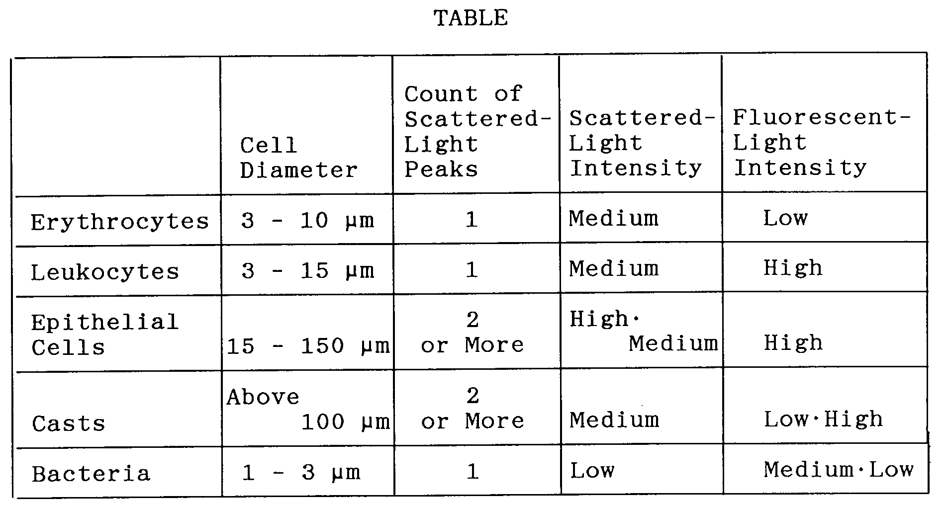
- In the table, the cell diameters are values decided statistically upon actually measuring the erythrocytes, leukocytes, epithelial cells, casts and bacteria in a urine specimen using a microscope. The intensity of forward-scattered light reflects a plurality of items of information, such as cell size, density and surface configuration. There are cells (epithelial cells) for which the intensity of scattered light is high, cells (erythrocytes, leukocytes, casts and some epithelial cells) for which the intensity is medium, and cells (bacteria) for which the intensity is low. The intensity of the fluorescent light is information proportional to the amount of DNA. There are cells (leukocytes, epithelial cells and casts in which cells are sealed) for which the intensity of fluorescent light is high, cells (bacteria) for which the intensity is medium, and cells (bacteria, erythrocytes, hyaline casts) for which the intensity is low. The reason for the low fluorescent intensity of glass casts is that these do not contain DNA. In addition, though bacteria contain DNA, the cells are small in size and therefore the amount of DNA content is small in comparison with other cells. The intensity of fluorescent light also is medium or low. Though there are instances where a number of bacteria clumps in urine, the count of scattered-light peaks is one in the case of erythrocytes, leukocytes and unclumped bacteria and two or more for large cells having a complicated internal structure, such as in the case of epithelial cells and casts.
- Under these conditions, the items of forward-scattered light intensity data, forward fluorescent-light intensity data and pulse-width data associated with each cell are stored, on a cell-by-cell basis, in the
memory circuit 42 whenever the trigger signal T, which is generated at each cell flow-by, enters the data processing portion 20. The pulse-width data is converted into cell-diameter data by thedata analyzer 43 based upon the aforementioned cell diameter conversion values, and the cell-diameter data obtained is stored in thememory circuit 42. The counter 41 counts the cells in successive fashion. This operation is carried out until the entirety of the urine specimen has passed through theflow cell 2. The storage and counting operations are executed atstep 51 in the flowchart of Fig. 3. When all of the urine specimen has passed through theflow cell 2, the total number of cells detected in the urine specimen is held in thecounter 41, and the items of forward-scattered light intensity data, forward fluorescent-light intensity data, data indicative of the count of scattered-light peaks and cell-diameter data associated with each cell detected in the urine specimen are stored in thememory circuit 42. - Under these conditions, the
data analyzer 43 reads the data for all cells out of thememory circuit 42 and then creates and displays various scatter diagrams (a), (b), (c) and (d) shown in the upper part of Fig. 14 (step 52). Observing the scatter diagrams of Fig. 14 makes it possible for the user to judge at a glance whether the results of urinalysis are normal or abnormal. In addition, the user can easily verify whether the scatter diagrams of Fig. 14 are indicative of patterns of an abnormal specimen. If the specimen is normal, almost no cells will appear in the scatter diagram. In Fig. 14, (a) is a scatter diagram of scattered light intensity and fluorescent light intensity, (b) a scatter diagram of fluorescent light intensity and cell diameter, (c) a scatter diagram of scattered-light intensity and cell diameter, and (d) a scatter diagram of the count of scattered-light peaks and cell diameter. - Each item of cell data is read out of the memory circuit 42 (step 53), and each cell is analyzed by the
data analyzer 43 in accordance with the cell judgment data in thememory 45. More specifically, if the data indicative of the count of scattered-light peaks of the read out cell is 1, the diameter of the read cell is 3 - 10 µm, the scattered-light intensity data is medium and the fluorescence intensity data is low, then the cell is judged to be an erythrocyte (steps 54 - 58). When a cell is judged to be an erythrocyte, thecounter 46 increments the erythrocyte count (step 60). If the cell is not an erythrocyte, it is judged to be another cell (step 61). - If the data indicative of the count of scattered-light peaks of the cell judged to be another cell is 1, the diameter of the cell is 3 - 15 µm, the scattered-light intensity data is medium and the fluorescence intensity data is high, then the cell is judged to be a leukocyte (steps 63 - 68). When a cell is judged to be a leukocyte, the
counter 46 increments the leukocyte count (step 69). If the cell is not a leukocyte, it is judged to be another cell (step 70). - If the data indicative of the count of scattered-light peaks of the cell judged to be another cell is 2 or more, the diameter of the cell is 15 - 150 µm, the scattered-light intensity data is high or medium and the fluorescence intensity data is high, then the cell is judged to be an epithelial cell (steps 71 - 76). When a cell is judged to be an epithelial cell, the
counter 46 increments the epithelial cell count (step 77). If the cell is not an epithelial cell, it is judged to be another cell (step 78). - If the data indicative of the count of scattered-light peaks of the cell judged to be another cell is 2 or more, the diameter of the cell is greater than 100 µm, the scattered-light intensity data is medium and the fluorescence intensity data is low or high, then the cell is judged to be a cast (steps 80 - 85). When a cell is judged to be a cast, the
counter 46 increments the cast count (step 86). If the cell is not a cast, it is judged to be another cell (step 87). - If the data indicative of the count of scattered-light peaks of the cell judged to be another cell is 1, the diameter of the cell is 1 - 3 µm, the scattered-light intensity data is low and the fluorescence intensity data is medium or low, then the cell is Judged to be a bacterium (steps 89 - 94). When a cell is judged to be a bacterium, the
counter 46 increments the bacteria count (step 95). If the cell is not a bacterium, it is judged to be another cell (step 96). Cell analysis is carried out for all detected cells (step 97), the erythrocyte count, leukocyte count, epithelial cell count, cast count and bacteria count per microliter of the urine specimen are calculated, and the calculated numerical values are displayed together with the cell count below the scatter diagrams of Fig. 14 (step 98). Thus, the results of highly accurate urinalysis can be obtained. - Though the foregoing embodiment has been illustrated taking forward-scattered light and forward fluorescent light as an example, it should be obvious that equally good results can be obtained using side-scattered light and side fluorescent light as well. If necessary, the display can be limited solely to the various cell counts without presenting a display of the scatter diagrams of Fig. 14.
- The apparatus of the invention described above is so adapted that scattered light and fluorescent light from individual cells in a urine specimen is detected by flow cytometry, data indicative of scattered-light intensity and data indicative of the count of scattered-light peaks is obtained from the scattered light, data indicative of fluorescent light intensity is obtained from the fluorescent light, the scattered light is converted into pulse signals, and pulse width is converted into data indicative of cell diameter in accordance with known cell diameters. Furthermore, actual-measurement data indicating the characteristics of each cell is stored in memory beforehand as cell judgement values, and the data indicative of the detected cells is analyzed in accordance with these cell judgment values.
- As a result, the cells contained in a urine specimen can be classified into erythrocytes, leukocytes, epithelial cells, casts and bacteria, etc., automatically.
- In particular, though it is difficult with the prior art to accurately sort blood cells from bacteria a number of which have clumped, the present invention makes use of data indicating the count of scattered-light peaks to select only cells for which the count of peaks is one, thereby making it possible to precisely classify cells into erythrocytes, leukocytes and unclumped bacteria. Moreover, since large cells such as casts and epithelial cells have two or more peaks, casts and epithelial cells also can be grouped correctly.
- In addition, the total number of cells in the urine specimen and the numbers of the individual types of cells in the specimen can be counted and displayed automatically and at high speed.
- As many apparently widely different embodiments of the present invention can be made without departing from the spirit and scope thereof, it is to be understood that the invention is not limited to the specific embodiments thereof except as defined in the appended claims.
Claims (18)
- An apparatus for analyzing cells in urine, comprising:
detecting means for irradiating with light a constricted zone through which various cells contained in a urine specimen flow in single file, and detecting scattered light and fluorescent light emitted by individual cells, said cells having been stained with a stain so that DNA will specifically emit fluorescence; and
means for classifying and enumerating the various cells in the urine specimen based upon intensity, number of peaks and width of the scattered light and intensity of the fluorescent light detected by said detecting means. - The apparatus according to claim 1, wherein the cells classified and enumerated are erythrocytes.
- The apparatus according to claim 1, wherein the cells classified and enumerated are leukocytes.
- The apparatus according to claim 1, wherein the cells classified and enumerated are epithelial cells.
- The apparatus according to claim 1, wherein the cells classified and enumerated are casts.
- The apparatus according to claim 1, wherein the cells classified and enumerated are bacteria.
- An apparatus for analyzing cells in urine, comprising:
first means for irradiating with light a constricted zone through which various cells contained in a urine specimen flow in single file, and detecting scattered light and fluorescent light emitted by individual cells, said cells having been stained with a stain so that DNA will specifically emit fluorescence;
a first photoelectric converting circuit for converting the scattered light detected by said first means into an electric signal output;
a second photoelectric converting circuit for converting the fluorescent light detected by said first means into an electric signal output;
second means for generating scattered-light intensity data based upon the electric signal output from said first photoelectric converting circuit;
third means for generating peak-count data, which is indicative of the count of scattered-light peaks, based upon the electric signal output from said first photoelectric converting circuit;
fourth means for generating fluorescent-light intensity data based upon the electric signal output from said second photoelectric converting circuit;
fifth means for converting the electric signal output from said first photoelectric converting circuit into pulse-width data;
sixth means for converting the pulse-width data obtained by said fifth means into cell-diameter data;
memory means in which cell diameter, scattered-light intensity, the count of scattered-light peaks and fluorescent light intensity, which are indicative of the characteristics of individual cells and are obtained statistically upon carrying out actual measurement of various cells in urine, are stored in advance as cell judgment values;
seventh means for classifying and enumerating each of the cells in the urine specimen by analyzing, based upon the cell judgment values, the data generated by said second means, the data generated by said third means, the data generated by said fourth means and the data resulting from the conversion performed by said sixth means for each cell; and
eighth means for displaying the cell classifications and cell counts obtained by said seventh means. - The apparatus according to claim 7, wherein the cells classified and enumerated are erythrocytes.
- The apparatus according to claim 7, wherein the cells classified and enumerated are leukocytes.
- The apparatus according to claim 7, wherein the cells classified and enumerated are epithelial cells.
- The apparatus according to claim 7, wherein the cells classified and enumerated are casts.
- The apparatus according to claim 7, wherein the cells classified and enumerated are bacteria.
- The apparatus according to claim 7, wherein said cell judgment values for judging a cell to be an erythrocyte are a peak count of 2 or more, a cell diameter of 3 - 10 µm, a scattered-light intensity which is medium, and a fluorescent light intensity which is low.
- The apparatus according to claim 7, wherein said cell judgment values for judging a cell to be a leukocyte are a peak count of 1, a cell diameter of 3 - 15 µm, a scattered-light intensity which is medium, and a fluorescent light intensity which is high.
- The apparatus according to claim 7, wherein said cell judgment values for judging a cell to be an epithelial cell are a peak count of 2 or more, a cell diameter of 15 - 150 µm, a scattered-light intensity which is medium or high, and a fluorescent light intensity which is high.
- The apparatus according to claim 7, wherein said cell judgment values for Judging a cell to be a cast are a peak count of 2 or more, a cell diameter of greater than 100 µm, a scattered-light intensity which is medium, and a fluorescent light intensity which is low or high.
- The apparatus according to claim 7, wherein said cell judgment values for Judging a cell to be a bacterium are a peak count of 1, a cell diameter of 1 - 3 µm, a scattered-light intensity which is low, and a fluorescent light intensity which is low or medium.
- A method of analyzing cells in urine, comprising the steps of staining cells in a urine specimen with a stain such that DNA will specifically emit fluorescence, irradiating with light a constricted zone through which stained cells flow in single file, detecting scattered light and fluorescent light emitted by individual cells, and classifying and emunerating the various cells in the specimen based upon intensity, number of peaks and width of the detected scattered light and intensity of the detected fluorescent light.
Applications Claiming Priority (2)
| Application Number | Priority Date | Filing Date | Title |
|---|---|---|---|
| JP108057/91 | 1991-05-14 | ||
| JP03108057A JP3098273B2 (en) | 1991-05-14 | 1991-05-14 | Urine cell analyzer |
Publications (2)
| Publication Number | Publication Date |
|---|---|
| EP0514178A1 true EP0514178A1 (en) | 1992-11-19 |
| EP0514178B1 EP0514178B1 (en) | 1996-04-17 |
Family
ID=14474822
Family Applications (1)
| Application Number | Title | Priority Date | Filing Date |
|---|---|---|---|
| EP92304371A Expired - Lifetime EP0514178B1 (en) | 1991-05-14 | 1992-05-14 | Apparatus for analyzing cells in urine |
Country Status (6)
| Country | Link |
|---|---|
| US (1) | US5325169A (en) |
| EP (1) | EP0514178B1 (en) |
| JP (1) | JP3098273B2 (en) |
| AU (1) | AU1622492A (en) |
| CA (1) | CA2068490A1 (en) |
| DE (1) | DE69209886T2 (en) |
Cited By (7)
| Publication number | Priority date | Publication date | Assignee | Title |
|---|---|---|---|---|
| WO1995000661A1 (en) * | 1993-06-24 | 1995-01-05 | The Minister Of Agriculture Fisheries And Food In Her Britannic Majesty's Government Of The United Kingdom Of Great Britain And Northern Ireland | Detection of microbial growth |
| EP0780678A3 (en) * | 1995-12-19 | 1999-02-10 | TOA MEDICAL ELECTRONICS CO., Ltd. | Analyzer for analyzing urine material components |
| EP0780680A3 (en) * | 1995-12-19 | 1999-12-15 | Sysmex Corporation | Analyzer for analyzing urine material components |
| US6087182A (en) * | 1998-08-27 | 2000-07-11 | Abbott Laboratories | Reagentless analysis of biological samples |
| EP0949498A3 (en) * | 1998-04-08 | 2003-04-16 | Sysmex Corporation | Apparatus and method for differentiating erythrocytes in urine |
| CN102207444A (en) * | 2011-03-17 | 2011-10-05 | 上海理工大学 | Image-method particle-size analyzer |
| EP2990799A1 (en) * | 2014-08-25 | 2016-03-02 | Sysmex Corporation | Method for analyzing atypical cells in urine and urine analyzer |
Families Citing this family (21)
| Publication number | Priority date | Publication date | Assignee | Title |
|---|---|---|---|---|
| JP2941041B2 (en) * | 1990-11-16 | 1999-08-25 | シスメックス株式会社 | Classification of leukocytes by flow cytometry |
| JP3070968B2 (en) * | 1991-05-14 | 2000-07-31 | シスメックス株式会社 | Urine cell analysis reagents and methods |
| US5585246A (en) * | 1993-02-17 | 1996-12-17 | Biometric Imaging, Inc. | Method for preparing a sample in a scan capillary for immunofluorescent interrogation |
| EP0716299A4 (en) * | 1994-06-27 | 1998-03-04 | Furukawa Electric Co Ltd | Apparatus for detecting foreign matter in fluid |
| DE69533469T2 (en) * | 1994-12-26 | 2005-09-22 | Sysmex Corp. | flow cytometer |
| DE69601258T2 (en) * | 1995-01-24 | 1999-06-17 | Chipper 2000 Isle Of Man Ltd | COLOR DETECTING DEVICE |
| KR100461987B1 (en) * | 1995-12-06 | 2005-07-01 | 시스멕스 가부시키가이샤 | Data check device |
| US6034769A (en) * | 1997-06-27 | 2000-03-07 | Yufa; Aleksandr L. | Method and device for counting and measuring particles |
| US5870190A (en) * | 1997-11-25 | 1999-02-09 | Venturedyne, Ltd. | Particle sensor and related method offering improved particle discrimination |
| IL126881A0 (en) * | 1998-11-04 | 1999-09-22 | Dan Gottlieb | Image analysis of urine |
| AU2001290509A1 (en) * | 2000-06-07 | 2001-12-17 | Clifford A. Megerle | System and method to detect the presence of a target organism within an air sample using flow cytometry |
| JP2002202241A (en) | 2000-10-30 | 2002-07-19 | Sysmex Corp | Electrolytic solution for particle measuring instrument |
| JP4751535B2 (en) * | 2001-07-26 | 2011-08-17 | シスメックス株式会社 | Fractionation method and blood analyzer using the same |
| ATE339687T1 (en) * | 2002-05-22 | 2006-10-15 | Sysmex Corp | IMMUNOLOGICAL METHODS, DEVICES AND REAGENTS |
| JP4413120B2 (en) * | 2004-09-30 | 2010-02-10 | シスメックス株式会社 | Analytical particle analysis method and analyzer |
| US8409509B2 (en) * | 2007-04-12 | 2013-04-02 | Regents Of The University Of Minnesota | Systems and methods for analyzing a particulate |
| US8654319B2 (en) | 2009-01-23 | 2014-02-18 | University Of Maryland, Baltimore County | Chlorophyll and turbidity sensor system |
| WO2010148332A2 (en) * | 2009-06-19 | 2010-12-23 | Regents Of The University Of Minnesota | Systems and methods for analyzing a particulate |
| SG11201607145VA (en) * | 2014-02-28 | 2016-10-28 | Sysmex Corp | Method for urine sample analysis, reagent for urine sample analysis, and reagent kit for urine sample analysis |
| JP6680492B2 (en) * | 2015-09-11 | 2020-04-15 | シスメックス株式会社 | Cell analyzer and cell analysis method |
| LU100777B1 (en) | 2018-04-23 | 2019-10-23 | Cytena Gmbh | A method of assaying a liquid containing at least one cell and / or at least one particle |
Citations (6)
| Publication number | Priority date | Publication date | Assignee | Title |
|---|---|---|---|---|
| US3675768A (en) * | 1969-03-17 | 1972-07-11 | Gildardo Legorreta Sanchez | Method and apparatus for classifying and segregating particles with electrical and optical means |
| US4021117A (en) * | 1975-08-07 | 1977-05-03 | Hildegard Gohde | Process for automatic counting and measurement of particles |
| US4263508A (en) * | 1979-04-20 | 1981-04-21 | Research Corporation | Pulse edge measurement for determining particle dimensional characteristics |
| US4661913A (en) * | 1984-09-11 | 1987-04-28 | Becton, Dickinson And Company | Apparatus and method for the detection and classification of articles using flow cytometry techniques |
| EP0268766A2 (en) * | 1986-11-27 | 1988-06-01 | Toa Medical Electronics Co., Ltd. | Method of classifying leukocytes by flow cytometry and reagents used in the method |
| US4986657A (en) * | 1987-07-31 | 1991-01-22 | Canon Kabushiki Kaisha | Apparatus for analyzing particles using scattered and fluorescent light |
Family Cites Families (3)
| Publication number | Priority date | Publication date | Assignee | Title |
|---|---|---|---|---|
| US4338024A (en) * | 1980-05-02 | 1982-07-06 | International Remote Imaging Systems, Inc. | Flow analyzer and system for analysis of fluids with particles |
| US4765737A (en) * | 1987-03-30 | 1988-08-23 | Cornell Research Foundation | Cell size measurements using light in flow cytometry and cell sorting |
| JP2827300B2 (en) * | 1989-07-18 | 1998-11-25 | アイシン精機株式会社 | Ultrasonic motor |
-
1991
- 1991-05-14 JP JP03108057A patent/JP3098273B2/en not_active Expired - Lifetime
-
1992
- 1992-05-12 CA CA002068490A patent/CA2068490A1/en not_active Abandoned
- 1992-05-13 US US07/882,418 patent/US5325169A/en not_active Expired - Fee Related
- 1992-05-13 AU AU16224/92A patent/AU1622492A/en not_active Abandoned
- 1992-05-14 DE DE69209886T patent/DE69209886T2/en not_active Expired - Fee Related
- 1992-05-14 EP EP92304371A patent/EP0514178B1/en not_active Expired - Lifetime
Patent Citations (6)
| Publication number | Priority date | Publication date | Assignee | Title |
|---|---|---|---|---|
| US3675768A (en) * | 1969-03-17 | 1972-07-11 | Gildardo Legorreta Sanchez | Method and apparatus for classifying and segregating particles with electrical and optical means |
| US4021117A (en) * | 1975-08-07 | 1977-05-03 | Hildegard Gohde | Process for automatic counting and measurement of particles |
| US4263508A (en) * | 1979-04-20 | 1981-04-21 | Research Corporation | Pulse edge measurement for determining particle dimensional characteristics |
| US4661913A (en) * | 1984-09-11 | 1987-04-28 | Becton, Dickinson And Company | Apparatus and method for the detection and classification of articles using flow cytometry techniques |
| EP0268766A2 (en) * | 1986-11-27 | 1988-06-01 | Toa Medical Electronics Co., Ltd. | Method of classifying leukocytes by flow cytometry and reagents used in the method |
| US4986657A (en) * | 1987-07-31 | 1991-01-22 | Canon Kabushiki Kaisha | Apparatus for analyzing particles using scattered and fluorescent light |
Non-Patent Citations (1)
| Title |
|---|
| REVIEW OF SCIENTIFIC INSTRUMENTS. vol. 55, no. 9, September 1984, NEW YORK US pages 1375 - 1400; J. A. STEINKAMP: 'Flow cytometry' * |
Cited By (14)
| Publication number | Priority date | Publication date | Assignee | Title |
|---|---|---|---|---|
| WO1995000661A1 (en) * | 1993-06-24 | 1995-01-05 | The Minister Of Agriculture Fisheries And Food In Her Britannic Majesty's Government Of The United Kingdom Of Great Britain And Northern Ireland | Detection of microbial growth |
| GB2294320A (en) * | 1993-06-24 | 1996-04-24 | Mini Agriculture & Fisheries | Detection of microbial growth |
| EP0780678A3 (en) * | 1995-12-19 | 1999-02-10 | TOA MEDICAL ELECTRONICS CO., Ltd. | Analyzer for analyzing urine material components |
| EP0780680A3 (en) * | 1995-12-19 | 1999-12-15 | Sysmex Corporation | Analyzer for analyzing urine material components |
| EP0949498A3 (en) * | 1998-04-08 | 2003-04-16 | Sysmex Corporation | Apparatus and method for differentiating erythrocytes in urine |
| US6426045B1 (en) | 1998-08-27 | 2002-07-30 | Abbott Laboratories | Reagentless analysis of biological samples |
| US6365109B1 (en) | 1998-08-27 | 2002-04-02 | Abbott Laboratories | Reagentless analysis of biological samples |
| US6087182A (en) * | 1998-08-27 | 2000-07-11 | Abbott Laboratories | Reagentless analysis of biological samples |
| US6773922B2 (en) | 1998-08-27 | 2004-08-10 | Abbott Laboratories | Reagentless analysis of biological samples |
| CN102207444A (en) * | 2011-03-17 | 2011-10-05 | 上海理工大学 | Image-method particle-size analyzer |
| CN102207444B (en) * | 2011-03-17 | 2012-10-03 | 上海理工大学 | Image-method particle-size analyzer |
| EP2990799A1 (en) * | 2014-08-25 | 2016-03-02 | Sysmex Corporation | Method for analyzing atypical cells in urine and urine analyzer |
| CN105388099A (en) * | 2014-08-25 | 2016-03-09 | 希森美康株式会社 | Urine analyzing device and method for analyzing atypical cells in urine or body fluid |
| US10309877B2 (en) | 2014-08-25 | 2019-06-04 | Sysmex Corporation | Method for analyzing atypical cells in urine, urine analyzer, and method for analyzing atypical cells in body fluid |
Also Published As
| Publication number | Publication date |
|---|---|
| JPH05322883A (en) | 1993-12-07 |
| DE69209886D1 (en) | 1996-05-23 |
| DE69209886T2 (en) | 1996-08-14 |
| US5325169A (en) | 1994-06-28 |
| EP0514178B1 (en) | 1996-04-17 |
| AU1622492A (en) | 1992-11-19 |
| CA2068490A1 (en) | 1992-11-15 |
| JP3098273B2 (en) | 2000-10-16 |
Similar Documents
| Publication | Publication Date | Title |
|---|---|---|
| EP0514178B1 (en) | Apparatus for analyzing cells in urine | |
| EP0515099A1 (en) | Apparatus for analyzing cells in urine | |
| EP0022670B1 (en) | Method and apparatus for automated identification and enumeration of specified blood cell subclasses | |
| JP5058171B2 (en) | Method and apparatus for performing platelet measurements | |
| EP0698211B1 (en) | Reticulocyte analyzing method and apparatus utilizing light scatter techniques | |
| US7008792B2 (en) | Method of measurement of nucleated red blood cells | |
| JP2635126B2 (en) | Particle analysis apparatus and method for determining nuclear leaf index | |
| EP1865303A1 (en) | Method of discriminating cancer and atypical cells and cell analyzer | |
| US6118522A (en) | Apparatus and method for differentiating erythrocytes in urine | |
| EP2694960A2 (en) | Identifying and enumerating early granulated cells (egcs) | |
| EP0515100B1 (en) | Apparatus for analyzing cells in urine | |
| JP2826448B2 (en) | Flow type particle image analysis method and flow type particle image analysis device | |
| JP4279900B2 (en) | Simultaneous analysis of cell viability, nucleated red blood cells, and white blood cell classification | |
| Gray et al. | A new method for cell volume measurement based on volume exclusion of a fluorescent dye | |
| JP2002277381A (en) | Particle analyzer | |
| JPH05322882A (en) | Blood analyzing instrument | |
| Lewis | Automation in haematology-present and future trends | |
| Persaud | Development of a helium-neon laser based flow cytometer for evaluation of particulate matter | |
| JPS5897768A (en) | Hemocyte sorting device |
Legal Events
| Date | Code | Title | Description |
|---|---|---|---|
| PUAI | Public reference made under article 153(3) epc to a published international application that has entered the european phase |
Free format text: ORIGINAL CODE: 0009012 |
|
| AK | Designated contracting states |
Kind code of ref document: A1 Designated state(s): DE FR GB IT NL |
|
| 17P | Request for examination filed |
Effective date: 19930201 |
|
| 17Q | First examination report despatched |
Effective date: 19950531 |
|
| GRAH | Despatch of communication of intention to grant a patent |
Free format text: ORIGINAL CODE: EPIDOS IGRA |
|
| GRAA | (expected) grant |
Free format text: ORIGINAL CODE: 0009210 |
|
| AK | Designated contracting states |
Kind code of ref document: B1 Designated state(s): DE FR GB IT NL |
|
| ITF | It: translation for a ep patent filed |
Owner name: INTERPATENT ST.TECN. BREV. |
|
| REF | Corresponds to: |
Ref document number: 69209886 Country of ref document: DE Date of ref document: 19960523 |
|
| ET | Fr: translation filed | ||
| PLBE | No opposition filed within time limit |
Free format text: ORIGINAL CODE: 0009261 |
|
| STAA | Information on the status of an ep patent application or granted ep patent |
Free format text: STATUS: NO OPPOSITION FILED WITHIN TIME LIMIT |
|
| 26N | No opposition filed | ||
| PGFP | Annual fee paid to national office [announced via postgrant information from national office to epo] |
Ref country code: GB Payment date: 20000510 Year of fee payment: 9 Ref country code: FR Payment date: 20000510 Year of fee payment: 9 |
|
| PGFP | Annual fee paid to national office [announced via postgrant information from national office to epo] |
Ref country code: NL Payment date: 20000531 Year of fee payment: 9 |
|
| PG25 | Lapsed in a contracting state [announced via postgrant information from national office to epo] |
Ref country code: GB Free format text: LAPSE BECAUSE OF NON-PAYMENT OF DUE FEES Effective date: 20010514 |
|
| PG25 | Lapsed in a contracting state [announced via postgrant information from national office to epo] |
Ref country code: NL Free format text: LAPSE BECAUSE OF NON-PAYMENT OF DUE FEES Effective date: 20011201 |
|
| GBPC | Gb: european patent ceased through non-payment of renewal fee |
Effective date: 20010514 |
|
| PG25 | Lapsed in a contracting state [announced via postgrant information from national office to epo] |
Ref country code: FR Free format text: LAPSE BECAUSE OF NON-PAYMENT OF DUE FEES Effective date: 20020131 |
|
| NLV4 | Nl: lapsed or anulled due to non-payment of the annual fee |
Effective date: 20011201 |
|
| PGFP | Annual fee paid to national office [announced via postgrant information from national office to epo] |
Ref country code: DE Payment date: 20020522 Year of fee payment: 11 |
|
| PG25 | Lapsed in a contracting state [announced via postgrant information from national office to epo] |
Ref country code: DE Free format text: LAPSE BECAUSE OF NON-PAYMENT OF DUE FEES Effective date: 20031202 |
|
| PG25 | Lapsed in a contracting state [announced via postgrant information from national office to epo] |
Ref country code: IT Free format text: LAPSE BECAUSE OF NON-PAYMENT OF DUE FEES;WARNING: LAPSES OF ITALIAN PATENTS WITH EFFECTIVE DATE BEFORE 2007 MAY HAVE OCCURRED AT ANY TIME BEFORE 2007. THE CORRECT EFFECTIVE DATE MAY BE DIFFERENT FROM THE ONE RECORDED. Effective date: 20050514 |